Advertisement
If you have a new account but are having problems posting or verifying your account, please email us on hello@boards.ie for help. Thanks :)
Hello all! Please ensure that you are posting a new thread or question in the appropriate forum. The Feedback forum is overwhelmed with questions that are having to be moved elsewhere. If you need help to verify your account contact hello@boards.ie
Hi all! We have been experiencing an issue on site where threads have been missing the latest postings. The platform host Vanilla are working on this issue. A workaround that has been used by some is to navigate back from 1 to 10+ pages to re-sync the thread and this will then show the latest posts. Thanks, Mike.
Hi there,
There is an issue with role permissions that is being worked on at the moment.
If you are having trouble with access or permissions on regional forums please post here to get access: https://www.boards.ie/discussion/2058365403/you-do-not-have-permission-for-that#latest

Spitfire Total Rebuild!

2456710

Comments

  • Registered Users, Registered Users 2 Posts: 2,574 ✭✭✭dharn


    Does the zinc coating make mig welding more difficult


  • Registered Users, Registered Users 2 Posts: 4,506 ✭✭✭SpitfireIV


    dharn wrote: »
    Does the zinc coating make mig welding more difficult

    Theres only a very lite, indeed a dusting of zinc on the sheets. Generally I'd clean it back with the flap wheel where its going to be welded, but, it doesnt seem to cause an issue with the welding; just burns away.


  • Registered Users, Registered Users 2 Posts: 4,506 ✭✭✭SpitfireIV


    Lower inner wing panel/boot section was rusted beyond repair, now, although it was just the lower edge it would prove difficult to try and work around the windows/strengtheners, so, a complete replacement was fitted.


    1932729_10153991668125591_4555157515605409113_o.jpg
    ^ Looking a bit.....rusty, but, not bad for a 43 year old car I guess.


    1980356_10153991668245591_7100951771140178842_o.jpg
    ^ Replacement section in for a dry fit. The bumper iron mounting point will be fixed on later.


    1979123_10154088870135591_13858606021101650_o.jpg
    ^ Next up is that rusty wheel arch. Its for the most part salvageable and just requires some patching.


    10305064_10154088870140591_6338811084783882471_n.jpg?oh=b51b3b088d4ee415599b3a46f59974a8&oe=540D91F8&__gda__=1412145309_09d4f78e94ed6d00a1d7ab79db7407e4
    ^ Rear section of the arch, this has to go also!


    10341613_10154088870425591_8543310143709151573_n.jpg
    ^ Marked and ready for the chop!


    10272707_10154088870680591_8993796448286851336_o.jpg
    ^ Trying out a template.


    1911957_10154088870510591_3472884583043236718_o.jpg
    ^ Trial fit.


    1978383_10154088870690591_2881695286760219078_o.jpg
    ^ Bit of cutting and a few sparks later and this is what you get. Now, where'd I leave those flap discs??


    1897800_10154088870820591_3917897495131643296_n.jpg
    ^ Front of the arch repair sections being offered up for a trial fit.


    10317677_10154088871450591_4666018714203798489_o.jpg
    ^ Some of the welds on the arch cleaned up and given a quick coat of rust primer to hold her over. Some more welding will be done where the wheel arch meets the boot repair panel. Also note the mounting point for the bumper iron has been fitted.


    1800293_10154030077690591_3742284401301671620_n.jpg
    ^ Threw on the wing for a trial fit and the door gap dont look too bad at all!


    10256572_10154088871730591_326668185373181689_o.jpg
    ^ Next time we'll be trying to cleanly remove this driver side sill for reuse and see just how much of the floor on this side can be salvaged (or indeed, how much is to be cut away!).....


  • Registered Users, Registered Users 2 Posts: 2,574 ✭✭✭dharn


    Good stuff


  • Registered Users, Registered Users 2 Posts: 1,273 ✭✭✭Daved_XB


    Epic work & skills.. Well done, I've always done all my own mechanical work on my two projects, but the body work stuff has always been out of my depth... But I have just started a nighttime welding course to see if I can't have a go at the next project whatever that my be.. Looking forward to more updates as you go..


  • Registered Users, Registered Users 2 Posts: 2,574 ✭✭✭dharn


    I recon the welding would be the easy bit, forming the parts shaping the metal etc is really difficult


  • Registered Users, Registered Users 2 Posts: 1,273 ✭✭✭Daved_XB


    dharn wrote: »
    I recon the welding would be the easy bit, forming the parts shaping the metal etc is really difficult

    Well with a lot of the rust areas on the Muscle cars I own, they sell preformed repair panels that just need someone who's neat with a welder to weld in... The biggest danger is getting too much heat into the panel & warping them..

    The welding course I've just started also covers shrinking for just such a disaster :)


  • Registered Users, Registered Users 2 Posts: 4,506 ✭✭✭SpitfireIV


    Cheers guys! :o I must add, if I havent already, that I cant claim credit for the welding, my neighbour is a master at that so I leave that to him, I'd love to be able to weld myself, but, its a skill that needs to be learned properly I reckon and done right. Fabricating the repair sections, panels etc; that I can do and enjoy! :D


    Right, on to the driver side floorpan and getting that sill off! Like a lot of previous work done on this car the sill had been plug welded on badly, posistioned incorrectly and when a dose of filler was cleaned off the underside of the floorpan adjacent to the sill it was found to be a series of patches and poor repairs.

    Best course of action: - remove and reuse the sill and cut away and replace the bad section of floorpan.


    Hereeeee we go.....


    10268653_10154088871885591_1710643291014261080_n.jpg
    ^ Trying to remove the sill as cleanly as possible. Note also all the welds and repairs on the floorpan.


    10333645_10154088871800591_2919889943310484977_o.jpg
    ^ Floorpan patchwork.....gotta go!


    57463_10154088871625591_4269141706753012433_o.jpg
    ^ Inner sill looks solid, mid sill, from this angle, looks like scrap!!


    1501233_10154088872190591_5634901808794636579_o.jpg
    ^ Outer sill (rocker panel for any American viewers) removed. Forgot to take a picture of the mid sill before I cut it away, but, suffice to say it was cut away because it was rotten! Thankfully, as I thought, the inner sill was fine, just needed a cleaning and to be straightened up. Also note the base of the A pillar is totally rusted away at the floorpan!


    10258571_10154088872325591_849128122757875462_o.jpg
    ^ Floorpan marked up to be cut out.


    1956823_10154088872330591_8021705416432469526_o.jpg
    ^ Replacement section cut from 1.6mm mild steel and angle folded over to attach the mid sill to.


    10333664_10154088872475591_22382982049092635_o.jpg
    ^ Looks almost good enough to weld! You'll probably note that there are channels or ribs in the original floorpan, for strenght, however, the new repair section doesnt have these! Well, thats partially why I used the 1.6mm and eventually, in time, where the repair section meets the floorpan will be heated with a gas torch and hammered out to math the rib on the floorpan.


    10269030_10154088872700591_4834516301607736169_o.jpg
    ^ Repair section tack welded in and the spot welder busy at work spotting the inner sill to the new floorpan section. The new section will have to have mounting points for the seat and a seatbelt anchor fitted eventually.


    10012124_10154088872810591_4707275017624329818_o.jpg
    ^ New mid sill cut and bent to shape and spot welded to the inner sill and lip of the floorpan.


    10259104_10154088872915591_3829619026123071672_o.jpg
    ^ Instead of making a replacement section for the lower B post and a mid sid, I bent them all together in the one piece. It still needs to be welded in on top and folded slightly on the bottom left corner to straighten it out, but, it does the job!


    Next job then was to replace that rusty lower A post section. I had thought to try repair it, but, figured as I had a relatively new one in the donor/pile of scrap I'd retrieve that one, clean it up and stick it in!


    Now, where'd I leave the con saw???? Oh yes.......

    1909163_10154088872845591_8049820245131409493_o.jpg


  • Registered Users, Registered Users 2 Posts: 2,574 ✭✭✭dharn


    Croppy I noticed the original panel with the bumper bracket had a raised area pressed in to it probably for strengthening purposes, yours is just flat and the openings in it were ignored seems a pity as all your work so far is so good, this looks bodged ( just being a bit picky ):)


  • Advertisement
  • Registered Users, Registered Users 2 Posts: 4,506 ✭✭✭SpitfireIV


    dharn wrote: »
    Croppy I noticed the original panel with the bumper bracket had a raised area pressed in to it probably for strengthening purposes, yours is just flat and the openings in it were ignored seems a pity as all your work so far is so good, this looks bodged ( just being a bit picky ):)

    I would have liked to put the windows back in, but, to do it correct you'd need to joggle the edges of the window to add strenght; I dont have a joggler (although if I were to start the project again, for the sake of €50 or so I would have bought one).


  • Registered Users, Registered Users 2 Posts: 22,352 ✭✭✭✭endacl


    I would have liked to put the windows back in, but, to do it correct you'd need to joggle the edges of the window to add strenght; I dont have a joggler (although if I were to start the project again, for the sake of €50 or so I would have bought one).
    Things I learned today:

    (1) There's such a thing as 'joggling'.
    (2) To 'joggle', one needs a device, referred to by those who know, as a 'joggler'.

    Love this thread!

    :D


  • Registered Users, Registered Users 2 Posts: 4,358 ✭✭✭kev1.3s


    endacl wrote: »
    Things I learned today:

    (1) There's such a thing as 'joggling'.
    (2) To 'joggle', one needs a device, referred to by those who know, as a 'joggler'.

    Love this thread!

    :D

    I always taught it was juggling whilst running;)


  • Registered Users, Registered Users 2 Posts: 22,352 ✭✭✭✭endacl


    kev1.3s wrote: »
    I always taught it was juggling whilst running;)
    No, no, no.... You've got it all wrong. Its running whilst juggling.

    :p


  • Registered Users, Registered Users 2 Posts: 4,506 ✭✭✭SpitfireIV


    Smart asses! :p

    Joggle.jpeg

    Not as easy as it looks! :D


  • Registered Users, Registered Users 2 Posts: 2,574 ✭✭✭dharn


    Come on croppy, get back on track, cant wait for the next instalment :D


  • Advertisement
  • Registered Users, Registered Users 2 Posts: 4,358 ✭✭✭kev1.3s


    Yeah come on croppy, jog on.


  • Registered Users, Registered Users 2 Posts: 4,506 ✭✭✭SpitfireIV


    Okay okay....... :P


    Right, well, next up was to remove the lower A post section, which, truth be told was salvageable but, as I had an almost new section in the donor car I decided to remove the old one rather than try patch it. So, it was out with the spot weld drill bit again!


    10257903_10154144219825591_490473767696976962_o.jpg
    ^ Very handy little drill bit!!


    10272518_10154192027695591_6830542419653661867_o.jpg
    ^ Making a new repair section.....


    10362800_10154192027690591_4591705766029308928_o.jpg
    ^ The lower A post repair section in place and now trial fitting the angle repair section. Also note that by this stage the tub was giving a rough sanding in bare metal/rusty areas and a couple of quick sprays of rust primer to hold off the tin worm for a little while longer.


    10344305_10154192027745591_4144128538865921156_o.jpg
    ^ Cut to shape (even with the recess replicated; you'll like that dharn! :P )


    10383736_10154192027975591_1478669562086676664_o.jpg
    ^ Tacked into place.


    10359111_10154192027845591_4801576172334210186_o.jpg
    ^ Little repair/patch on the inside floorpan; it'll be cleaned down.


    10450031_10154286152900591_1411581176574893608_o.jpg
    ^ Somewhat limited access. The welder welding the floorpan to the new lower A post section and tying the A post upper and lower sections.


    10256626_10154192027940591_7663902060261810990_o.jpg
    ^ Door back on and jobs a good 'un!


    Next time we'll be constructing a DIY wheelarch section to replace this...! :eek:
    10338421_10154144219815591_8634470132702526687_o.jpg


  • Registered Users, Registered Users 2 Posts: 2,574 ✭✭✭dharn


    Those recesses are very important croppy !, is that ordinary galvanised flat sheeting you are using, I find that very hard to bend it seems very springy and hard , is the stuff car panels made from more malleable ?


  • Registered Users, Registered Users 2 Posts: 4,506 ✭✭✭SpitfireIV


    dharn wrote: »
    Those recesses are very important croppy !, is that ordinary galvanised flat sheeting you are using, I find that very hard to bend it seems very springy and hard , is the stuff car panels made from more malleable ?

    This isnt really galvanised, just has a dusting of zinc on it, but, otherwise its easy to work/fold/bend. Its a shade over 1mm, the car panels themselves are made of 1mm. Not sure what grade of steel it is, I did enquire prior to starting the project at a local steel suppliers to see if they sold 1mm, they said they only had it in galvanised and it was hard stuff to work, that I'd need 1mm cold rolled steel which they didnt supply. I was just lucky to come across a few small sheets, that I'm currently using, through the neighbour.


  • Registered Users, Registered Users 2 Posts: 4,506 ✭✭✭SpitfireIV


    Ok, arch repair; the one I had been dreading and putting on the long finger, but, it had to be done! Now, naturally I didnt wanna spend big bucks on replacement repair sections when I could have a go myself, right?


    http://www.rimmerbros.co.uk/Item--i-RB7365

    The bones of €150! no thanks! :pac:


    So, picked up a €5 sheet of light card and set about making up templates!


    1614150_10154144219840591_2818281638053242036_o.jpg
    ^ Time for this guy to bite the dust!


    1498919_10154144220045591_3040048542232786635_o.jpg
    ^ Marking up a template. I decided to make it in two halves for convinience.


    10293719_10154144220345591_2311987746824172854_o.jpg
    10273255_10154144220320591_310807916874767048_o.jpg
    ^ New section cut as per the template. You'll also notice the bad metal has been cut from the arch leaving just a 15mm lip to which the new pieces can be spotwelded too and will also give a rough idea of the angle.


    10322494_10154144220425591_7697008833244535647_n.jpg?oh=0e24cf1b550aa51bba1acec6858eadf8&oe=5436AF17
    ^ Must have been very busy by this stage as I'm lacking pics, but, essentially the same thing was done for the rear of the arch. A template was made, bad metal cut, new piece fitted and spotwelded into place.


    10397831_10154144220485591_1638416900733694715_n.jpg
    ^ A strenghtening rib was adding on the top of the arch. This new section would now have to be levelled off and cut stright on the front face before recieving the next section.


  • Advertisement
  • Registered Users, Registered Users 2 Posts: 4,358 ✭✭✭kev1.3s


    That's absolutely excellent work there, there's no reason you shoul dread any part of the metal fabrication


  • Registered Users, Registered Users 2 Posts: 4,506 ✭✭✭SpitfireIV


    Cheers Kev! ;)


    Update to thread may be getting few now as I'm getting closer to the current state of the build; and, at the moment it just seems to be a relentless amount of panel fitting, panel removal, panel modification....panel fitting, panel removal, panel modification....etc etc.......you get the idea!


    10431362_10154192027760591_6366002761265890377_o.jpg
    ^ So anyway, a replacement panel was cut, fitted and tacked in place in the rear inner wing/boot section; bumper iron bracket to be fitted later.


    10259051_10154192028685591_6688457819210578323_o.jpg
    ^ Another two lips were added to the diy inner wing, bit fiddly them are they are quite thin and narrow, so, a few metal tabs were spot welded around the inside of the arch first and then used to temporarily hold the new pieces in place. Dont have any decent pics, but, here she is (upside down).


    10269278_10154192028400591_9210659715135684761_o.jpg
    ^ So with the wheel arch just needed a proper weld job I got round to sorting the passagenger side floor strenghtner which I had folded up earlier.


    10397268_10154192028490591_64598858184754743_o.jpg
    ^ The original had recessed holes at angles through which bolts pass into the chassis underneath. These holes had to be in the right place and at the correct angle, so, I just cut out the particular section from the old one and reused it. Here it is being lined up and the bolts in place.

    Dont have a pic of it finished to hand at the mo, but the original section was flush welded into the new floor strenghtner and ground down and smoothed off! Came out perfect (take my word for it!! :p)


  • Registered Users, Registered Users 2 Posts: 4,506 ✭✭✭SpitfireIV


    Ok, here I am, havent forgot about you lot, just been busy! :D


    Right, well, as you seen in the previous posts I now had the most of the internal panels sorted! New mid sills (and one inner) made and fitted, arches repaired, so, now it was time to get a bonnet to use for panel alignment purposes, and start having a look at the external panels!


    10286767_10154233197160591_5041870874235858646_o.jpg
    ^ Spare bonnet fitted. Curiousity got the better of me so I clamped on the sill and rear wing and put two wheel on also.


    10448517_10154233197170591_6725967483467312468_o.jpg
    ^ View from the rear. Also note the hardtop had been cleaned back to bare metal and rust primed by this stage.


    10452953_10154233196945591_5743082141770428656_o.jpg
    ^ Cleaned a large quantity of filler off the bonnet arches and this was what lay underneath! :rolleyes: Someone went to a lot of effort, but, could have tried a little harder. Just as well this is only a temporary bonnet eh.


    10380606_10154286152980591_8600884746718263081_o.jpg
    ^ The Spitfire, even though it sits on a (modified Herald) chassis, requires structural support from its sills. Its a known weak point with them, they can rust at the sills (as I've seen) and the body can flex or even fold! Thus we figured, even with the good work that we had done on the sills, that adding extra strenght in the form of 40mm box section surely would hurt!


    10513344_10154286154010591_7257332204211040264_n.jpg?oh=b8d306d5cfc07eeeabdca2641be65be6&oe=54415182&__gda__=1413633495_733a867b178bfe89e4702522f16f2163
    ^ Theres no point simply welding a length of box to the mid sill, for it to be effective it has to be tied back into fixing/structural points in the car, hence, the two out riggers seen on the strengthening frame above.


    1529912_10154286153480591_242520806386076331_o.jpg
    ^ This view shows the angle of the box section to accommodate the angle of the mid sill compared to the outriggers which are parallel with the floor.


    10511564_10154286154085591_3818941414390134525_o.jpg
    ^ The out rigger to the rear would be tied into the rear link bar mounting bracket.


    10463824_10154286153495591_3210904807319407737_o.jpg
    ^ Out rigger to the front/mid would, like the rear one, go through the mid and inner sill and in this instance be attached to the floorpan cross member, near to a chassis mounting point.


    10507044_10154286152810591_4981460515908060739_o.jpg
    ^ Obviously, as mentioned, to fit this frame meant cutting through the sills and as such a little bit of strenght would be lost, but, we figured for the amount that was going to be lost a lot more would be gained once it was in place and welded up good an' proper!


    10431394_10154286154090591_6998441240901113499_o.jpg
    ^ Box section welded to mid sill and out rigger tacked onto floor crossmember.


    10476380_10154286154060591_3884772927123790969_o.jpg
    ^ Welded up and given a coat of rust primer.


    Now, hope the wait was worth it for you lot! :D


  • Registered Users, Registered Users 2 Posts: 4,506 ✭✭✭SpitfireIV


    Now for something a little different..........


    I'm not overly fond of the Spitty's rear lights! :o They always looked to me like a bit of an after thought; flat and bland....

    44883a.jpg
    (image taken from google)


    I decided I'd try something different, so, I picked up a set of Land Rover lights to see how they'd look.....


    10476334_10154282165150591_5382615824428823160_o.jpg

    10453027_10154282165195591_6932043554953034322_o.jpg

    10497922_10154282165205591_4977453017864471148_o.jpg


    Now, at first I did like them but then I figured they were a bit on the small side and not very interesting! Would have liked a chrome bezel or such. So, decided I wouldnt use the Landie lights but instead will go for slightly larger round Lucas lights with a chrome base....

    170511_med.jpg
    171011_med.jpg

    Combined with one of these....
    175005_med.jpg


    So the arrangement across the back light panel, left to right will be: Indicator-Stop/Tail--Reflector---Licence Plate---Reflector--Stop/Tail-Indicator. A separate reverse light will be fixed to the bumper.

    I hope to make a raised plinth/base to attach the indicator/stop lights on rather than have them plonked on a flat panel; watch this space......


  • Registered Users, Registered Users 2 Posts: 4,358 ✭✭✭kev1.3s


    I always taught the earlier spitfire rear end was prettier but I think it'll be difficult to change it without looking a bit kit car like. I'll watch with interest to see how you get on.


  • Registered Users, Registered Users 2 Posts: 1,258 ✭✭✭sogood


    I agree and imagine that the tendency to use the same lights on lots of different models of older English cars is a short cut that sacrifices a better appearance for the sake of economics. I think the rear lights featured on the Spitfire are the same lights that you'll find on the Triumph 2000 and possibly the Stag also. Maybe even the TR6. And the little round marker/indicator lights show up on Minis and Minors. The list is endless.

    And I agree that something a little bigger than the Landy lights would be nicer. BTW, still following this thread with great interest and admiration and perhaps you could advise on the following. When welding bodywork/panels, would an arc welder be as effective as a mig/tig welder, or would it generate more heat, with the attendant risk of causing warping? Thanks and keep up the excellent work.


  • Registered Users, Registered Users 2 Posts: 4,506 ✭✭✭SpitfireIV


    sogood wrote: »
    I agree and imagine that the tendency to use the same lights on lots of different models of older English cars is a short cut that sacrifices a better appearance for the sake of economics. I think the rear lights featured on the Spitfire are the same lights that you'll find on the Triumph 2000 and possibly the Stag also. Maybe even the TR6. And the little round marker/indicator lights show up on Minis and Minors. The list is endless.

    And I agree that something a little bigger than the Landy lights would be nicer. BTW, still following this thread with great interest and admiration and perhaps you could advise on the following. When welding bodywork/panels, would an arc welder be as effective as a mig/tig welder, or would it generate more heat, with the attendant risk of causing warping? Thanks and keep up the excellent work.

    You are correct sogood, a lot of fixtures and fittings were used throughout the British Leyland range, Lucas supplied the majority of the electrics and lenses etc. I think this particular arrangement the indicator lens and the chrome plinth they are mounted on is unique to the MkIV/1500 Spitfire, however, the rear light lenses are all locked together with, like a sliding dovetail joint so the other lenses, as you say would have been used on the other Triumph cars of the period.


    The landy lights are only 74mm in diameter, I hope to get the slightly larger 84mm with the chrome plinth. These particular lights would have been used on Imp's and I hope to, like to the Imp pictured below, make a slightly raised plinth on which both the lights can sit on (side by side) just to create a bit of interest and try not have it too 'kit car' looking :p


    Erics+new+Imp+paint+job+006.jpg


    As for the welding; I dont think an arch welder is up to the job; last time one was used on this project was to weld up the heavy frame for the rotisserie. With the panels being so thin we're using a MIG welder with .8 wire I believe, to get cleaner/finer welds I think .6 is recommended, but, I leave the welding to the neighbour, he's a master at it! I can just about manage an arch welder!

    Panel distortion is an issue though, so you have to do it in stages or small bits at a time.


  • Registered Users, Registered Users 2 Posts: 1,258 ✭✭✭sogood


    Thanks for the input. I have an arc welder that I have achieved decent results with, but figured that it might be a bit "heavy duty" for panel repairs.

    Anyway, keep up the good work! It's inspirational!!


  • Registered Users, Registered Users 2 Posts: 2,574 ✭✭✭dharn


    Whats the lightest rods that can be got for an arc welder ? 1.5 they would burn through those panels


  • Registered Users, Registered Users 2 Posts: 4,506 ✭✭✭SpitfireIV


    Hokey Dokey......


    So with the extra strengthening (in the form of 40mm box) added to the driver side it was now time to sort the rear wing and sills, get them in shape and stick em on!

    For this you will need -

    - Self tapper screws (dozen, approx)
    - Welding clamps (as many as you can beg borrow or steal!)
    - Two sets of hand (or, failing that, a helper)
    - Angle grinder, snips, cutting and grinding disks
    - A s&^t load of patience
    - Lots of time!


    10454072_10154286154185591_6250797540243290710_o.jpg
    ^ Driver side with reinforcing added. All rust primed and after the pic was taken all welds/seams/joints were given a coating of Dinitrol seam sealer.


    Now, the sills, as I mentioned in an earlier thread were relatively new, they were attached to the current front half of the tub I'm currently using but were put on badly (both in fit and attachment!) not to mention the mid sills were rotten so they needed to be accessed! Thus, the sills had be be removed as carefully as possible, however, its not so easy when youre dealing with large puddle welds and seam welds :rolleyes: so, the sills didnt come off as easily as I would have hoped, but, they came off regardless!!

    The abuse they got when being put on originally (evident by the amount of filler!) and the bit of abuse they got when being removed meant they were a little out of shape, so, the best thing for it was to make up a form over which they could be tested for correct shape and tapped back into shape if needs be.........which was, unfortunately the case :rolleyes:


    1556358_10154286154150591_7069769419942728354_o.jpg
    ^ Hardwood formers made up, both internal and external.


    This stage of the build took a lot of time (and patience.....even if it did wear thin at times!). I also only came to realise at this stage that these patent panels are not made to original specs and do require some surgery in order to get them to fit correctly; so, essentially, its really up to the individual and the individual car as to what alterations are needed to make it fit; bit of a head ache really. Hence it was a case of clamping/screwing the panel on, checking it over, taking it off and making adjustments....clamping/screwing the panel on, checking it over, taking it off and making adjustments....etc etc.


    10463609_10154286152850591_1809326289170251971_o.jpg
    ^ Starting to take shape! Its the gaps around the door that you have to watch out for, as well as the line where the bonnet meets the sill; gotta be even and straight!


    10506921_10154286154070591_3870489029003046827_o.jpg
    ^ Again, gradually getting there. You'll notice the joint where the sill meets the rear wing panel needs to be tightened up. This joint is supposed to remain unwelded to allow flex, but, as I have hopefully more or less removed the flex with the strengthening bars this joint will be welded up.


    10348729_10154286154040591_8647426192365520132_o.jpg
    10456006_10154286154130591_2567366644049226826_n.jpg
    ^ Not ging to get much better really! The reshaping and panel beating of the sills was beginning to stretch the lower portion of the sill causing a bit of a 'belly', but, it looks good enough, tight enough door gap and a good flow off the door onto the sill. You might notice the very front of the sill under the bonnet, the gap looks off, thats just because the panels still needed to be pushed down and clamped, but, its good! :)

    The seam on the bottom looks a bit wibbly wobbly. After its spotwelded on that can be levelled off and cleaned up.


    10256410_10154384675970591_3142467604822597107_o.jpg
    ^ Spot welded in place!! :)


  • Advertisement
  • Registered Users, Registered Users 2 Posts: 2,574 ✭✭✭dharn


    Brilliant work id say your shut lines, and panel lines will be better than when it was new,


  • Registered Users, Registered Users 2 Posts: 22,352 ✭✭✭✭endacl


    Just out of interest, would it not have been handier to just download a blueprint, buy a load of sheet metal, and just build a car from scratch?!?

    :p

    Great thread.


  • Registered Users, Registered Users 2 Posts: 2,574 ✭✭✭dharn


    A spitfire ,or just any oul car ?:confused:


  • Registered Users, Registered Users 2 Posts: 4,506 ✭✭✭SpitfireIV


    dharn wrote: »
    Brilliant work id say your shut lines, and panel lines will be better than when it was new,


    They look better in the pics then they really are! They're a pain to get right and have been told numerous times that its near impossible to do on a car that came out of the factory with bad lines/gaps to begin with!! :rolleyes:


  • Registered Users, Registered Users 2 Posts: 4,506 ✭✭✭SpitfireIV


    endacl wrote: »
    Just out of interest, would it not have been handier to just download a blueprint, buy a load of sheet metal, and just build a car from scratch?!?

    :p

    Great thread.


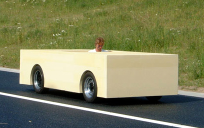
    Had crossed my mind once or twice alright yeah! :P In fairness though, if I did try I'd only end up with something like this....

    marijnvanderpoll.modular.jpg

    :P


  • Registered Users, Registered Users 2 Posts: 1,258 ✭✭✭sogood


    Hi croppy. No wish to hijack your excellent thread, but hoped you might be able to give me a little advice. As previously mentioned, I have a small arc welder, which I suspected might be a bit heavy duty for panel welding. This was indeed confirmed, so, any recommendations on a hobby type mig welder and what would be an acceptable amperage rating for welding up to about 4mm.
    I've seen gas/gasless models advertised, using cored wire etc. Any thoughts on this approach?

    Any thoughts or info much appreciated and keep up the great work.


  • Registered Users, Registered Users 2 Posts: 4,506 ✭✭✭SpitfireIV


    sogood wrote: »
    Hi croppy. No wish to hijack your excellent thread, but hoped you might be able to give me a little advice. As previously mentioned, I have a small arc welder, which I suspected might be a bit heavy duty for panel welding. This was indeed confirmed, so, any recommendations on a hobby type mig welder and what would be an acceptable amperage rating for welding up to about 4mm.
    I've seen gas/gasless models advertised, using cored wire etc. Any thoughts on this approach?

    Any thoughts or info much appreciated and keep up the great work.

    Hi sogood, sorry about the long wait. I'm afraid I'm not much help to you with regard welding. I know the neighbour thats helping me has two migs, a small and large but I couldnt event tell you the pro's and con's of both, their power ratings, etc etc. I just do the donkey work and let the expert take care of the welding. But, I'll be sure to ask! :)


    Now, you'll probably notice the ol' updates are slowing down, well, thats because I'm just about up to speed here with the progress so they definately wont be as open, but, never the less, the show goes on........


    In this update we'll be looking at the passenger side of the car, getting the sill and wing on and tackling the lack of the major panel work, ie the boot floor and rear valance.


    If you remember previously a strenghtening frame was made up and attached to the driver side, well, a similar set up was made and added to the passenger side and welded in place....

    10358917_10154384676530591_8075221096409931137_o.jpg
    ^ Box section added to passenger side and given a coat of rust pimer.


    10547423_10154384676220591_2972654955041005896_n.jpg
    ^ Sparks flying at night, the box section being welded in.


    1512237_10154384676535591_4963300206783858569_o.jpg
    ^ Welded in, cleaned up and rust proofed, ready to recieve the sill now!


    If you recall my previous post about the trouble I had reshaping the driver side sill and having to make up formers to knock it back into shape, well, those same formers didnt seem to fit properly into the passenger side sill! Thats the problem with a lot of these patent parts and different manufacturers, a lot of variance in measurements and tolerances! Headache...


    10518846_10154384676275591_7719754106808583451_o.jpg
    ^ Passenger sill knocked into shape and given an extra layer of rust proofing on the lower edges before having the seam flanges cleaned back to bare metal for the spot welder.


    10544361_10154384676520591_1952551114328801174_n.jpg?oh=54d2379e143f44410aa4dffbe39da6d0&oe=546E2571
    ^ Passenger wing rust proofed and the flanges cleaned back to bear metal and then it was read to go onto.........


    10506999_10154384676325591_9040507004298873121_o.jpg
    ^....this! Which, as you can see has also been cleaned back ready for fitting and spot welding.


    10577088_10154384676215591_4012930702794882098_n.jpg
    ^ If you can remember back earlier when I had to repair the 'new' driver side floorpan which had been attacked all 'chainsaw massacre' style by someone with an angle grinder. They had cut through the new rear wing and across the floor. I actually did have the piece put aside but I couldnt locate it, thus, I had to make up some kind of a filler piece.


    10553782_10154384676075591_7997404810117743647_o.jpg
    ^ Filler piece made from a piece of old sill, spotted to another piece of old sill which allowed for an overlap between the rest of the sill and the rear wing!


    10494961_10154384676895591_1651252298536004824_o.jpg
    ^ As good as it gets really. The ol' Triumphs are notroiously hard to get the panel gaps good or the doors sitting correctly! Its not bad. Disregard the bonnet here, it had dropped a little.


    10400876_10154384676510591_5284631708530611811_n.jpg
    ^ Threw on a bit of trim on the rear wing just for a look-see! :D


    Next up is the rear valance, boot floor and driver rear wing; the last of the major panel work!!!


  • Registered Users, Registered Users 2 Posts: 1,258 ✭✭✭sogood


    Hi croppy and thanks for the response. I have since gotten a small mig welder and am experimenting with it, getting a feel for it and its' operation.

    So far sogood, although I'm nowhere near ready to start any actual work on the car, still finishing off another project. So many restos, so little time.......

    And of course, keep up the good work!


  • Registered Users, Registered Users 2 Posts: 4,944 ✭✭✭Bigus


    Whats the rear light plan , I think you should keep them original, but if you're going twin light conversion are there any Ferrari ish retro LED light available instead of the imp type lights ?


  • Advertisement
  • Registered Users, Registered Users 2 Posts: 4,944 ✭✭✭Bigus


  • Registered Users, Registered Users 2 Posts: 4,944 ✭✭✭Bigus


    hella led rear combination lights

    led26007arr-j3barrm-led-rear-stoptailblinker-jumbo-3-in-1-led-autolamps-jumbo-led-tail-light---595mm-x-130mm-x-45mm.html


  • Registered Users, Registered Users 2 Posts: 4,506 ✭✭✭SpitfireIV


    sogood wrote: »
    Hi croppy and thanks for the response. I have since gotten a small mig welder and am experimenting with it, getting a feel for it and its' operation.

    So far sogood, although I'm nowhere near ready to start any actual work on the car, still finishing off another project. So many restos, so little time.......

    And of course, keep up the good work!

    I've only started experimenting myself with the MIG welder recently. Just spotting panels on and tacking things together until my neighbour is free to weld it up properly for me. It gives me a bit more freedom in that I can get things mocked up and in place in my own time and then get him to do the proper job on it.

    Its very hard trying to avoid burning holes in what is very thin metal! :rolleyes: But, inevitably holes do appear and then trying to chase them and fill them up! :mad:

    Ah, best left to the expert! :D


  • Registered Users, Registered Users 2 Posts: 4,506 ✭✭✭SpitfireIV


    Bigus wrote: »
    Whats the rear light plan , I think you should keep them original, but if you're going twin light conversion are there any Ferrari ish retro LED light available instead of the imp type lights ?


    Hi Bigus, many thanks for the links; appreciated!

    I have however since purchased a number of Lucas L691/L692 lamps (the ones previously pictured as seen on Imps, Austin Healey 3000's, some Lotus cars etc) at a car show, all original and all very cheap; cheaper than the new repro versions I was about to buy! ;) Stay tuned and you'll see how I have incorporated them into the rear panel of the car, I didnt just want to plonk them on the flat panel....


  • Registered Users, Registered Users 2 Posts: 4,506 ✭✭✭SpitfireIV


    So, the boot floor and rear valance!


    Major body work almost at an end, just a few more jobs to tackle!


    1045141_10154384676725591_7768022603945105825_n.jpg
    ^ Rear valance I suppose wasnt the worse, had some patches, a few holes, holes of filler and some rust for good measure, but, seen as I had a practically new one that was salvaged I decided to rip out the old one and replace with the 'new'


    10575458_10154384677000591_5548293981570830067_o.jpg
    ^ 'Twould tap out I 'spose!


    10463701_10154384676940591_7480108777761690580_o.jpg
    ^ Not much to talk about really. The bulk of the old one was chopped out then the spot welds drilled and the new one, after being cleaned up was put in place. Fit was pretty good and as I still had the original rear light panel in place I was pretty sure everything was good! :) Here the new panel can be seen in for a dry test fit.


    10472838_10154384677330591_5800649449470946025_o.jpg
    ^ Original boot floor; not so good! Again, I suppose with time and effort it could have been saved! It was rusted around the inner arches, had patches and, as can be seen from the pic below......


    1040233_10154384677400591_8761822345529664911_o.jpg
    ^....the bumper iron bracket came away, along with a section of the floor with just a little wiggle!!


    10528369_10154384677485591_9076206919046526675_o.jpg
    ^ Luckily however I had a 'new' salvaged boot floor; however, this unfortunately had also been attacked 'chain saw massacre' style with an angle grinder *sigh* to the driver side and was missing a section. But, not to worry.


    10550149_10154384677455591_8128416827078968954_o.jpg
    ^ Old boot floor cut out, leaving just a lip of the original floor upon which the new floor would sit.


    10329805_10154384677500591_5333913733406271875_o.jpg
    ^ Dry fit not looking too bad!


    10548091_10154437027630591_8104245742942326554_o.jpg
    ^ A missing section of the original boot floor lip welded in place. This lip would later be cut back to approx 15mm or so.


    Then, while waiting for the boot floor to be welded in I tackled the driver side wing!


    10515102_10154437027940591_8713305063660730963_o.jpg
    ^ Given a final coat of rust primer and then the weld areas cleaned back to bare metal.


    10603951_10154437028015591_7470798148659485274_o.jpg
    ^ Inside of the wing was also given an extra coating of rust primer on the lower sections and then a good dollop of Dinitrol seam sealer around the wheel arch to hopefully create a little bit of a seal between panels. Of course, these can be sealed up later from inside the car.


    10551540_10154437028175591_1692151070866430824_o.jpg
    ^ Wing spotted on and welder in the boot tacking the floor in place.


    10506814_10154437028535591_439683481130604259_o.jpg
    ^ Spun over to get at the underside of the bootfloor and weld it along the lip of the original floor.


    10411091_10154437028380591_1278784615438429463_n.jpg
    ^ Sparks a flyin!


    That is, the last of the major panel work done! Delighted!!! Now, of course, there are 101 smaller little jobs that need to me done, little patches, small areas of rust on the doors etc that need to be sorted. Its these jobs that will take a longggg time and you dont see any immediate result from it as opposed to banging on new panels, but, they must be done and so the show goes on.....


  • Advertisement
  • Closed Accounts Posts: 9,607 ✭✭✭toastedpickles


    I really want one of them spinny things haha everytime i see it :P

    Awesome work though :D


  • Registered Users, Registered Users 2 Posts: 4,506 ✭✭✭SpitfireIV


    I really want one of them spinny things haha everytime i see it :P

    Awesome work though :D


    Cheers! Ah, if you closely, well, you dont even have to look close! You'll see its pretty simple, made up of scraps, bit of tubing and a couple of scaffold stands. Thanfully however I had a seperate chassis that I could mount this to and then build the tub on top of this; dont know how you'd do it with a chassis-less car.


    Now its gets controversial!! Purists, divert your eyes!!


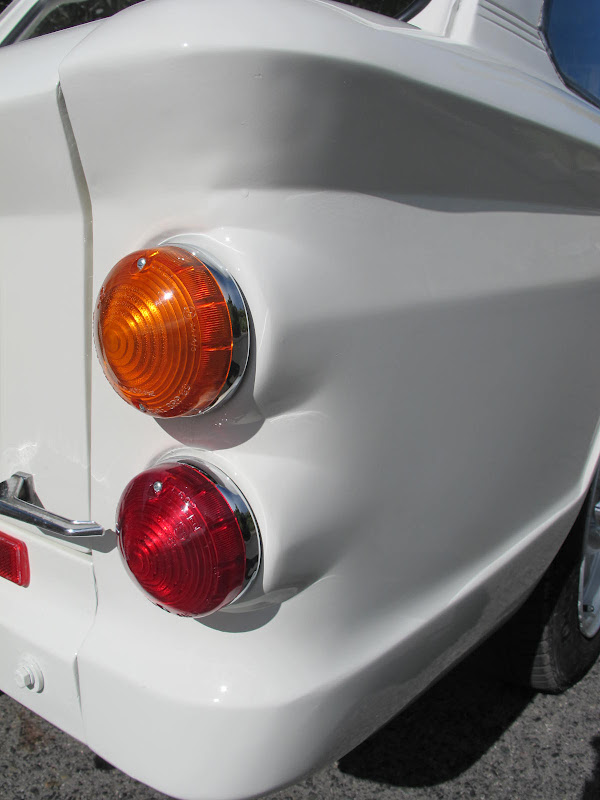
    Now, you'll remember my light modification ideas. I simply dont like the cluster /slab lights on the tail of the Spitfire, I see them as an after thought, ill concieved and bland. Besides, I figure this car is my baby and I'm not out to satisfy the purists or make it look as it did when it rolled out of the factory, there are enough examples that look like that! Thus, I want to make this car unique, different, one of a kind....my car! :cool:


    So, I had tried the landie lights, but, found them to be too small at 70mm and a bit; basic. Next (and most affordable) option was Lucas L691/692 light fittings that were contemporary with the Spitfire but never used on them. I had found a supplier in the UK and was about to purchase when I visitied a local car show and picked up a load of original bases and lens for a few euro; they were very grubby but cleaned up nicely!!


    1553146_10154439988410591_5899558916635712354_o.jpg
    ^ So here are the lights wedged in place along with some reflectors, just for a look-see. It was convenient that the holes for the original lines were 84mm, just the size of the chrome bezel of the new lights! ;)


    10532831_10154439987910591_2181643134393885458_o.jpg
    ^ Just pushed in place, litterally minutes after I got them home.


    10547476_10154439988340591_2279557718066839245_n.jpg
    ^ Original Lucas reflector also.


    Now, my plan was to use this layout and fit a reversing light under the bumper. But, with some thought and consideration, plus a few pointers from a few (and I mean very few) in the Spitfire world I decided I would go with three lights on either side and make a feature of them or create a bit of interest rather than just plonking them all on the flat panel.

    So, I set to work....


  • Registered Users, Registered Users 2 Posts: 4,506 ✭✭✭SpitfireIV


    10548141_10154452187745591_938881628429457603_o.jpg
    ^ Forming a bit of 1mm that would be the side wall for a recessed light panel.


    10497195_10154452188270591_6368777484254077635_o.jpg
    ^ Base in place.


    10498511_10154452187905591_3279265013099625407_o.jpg
    ^ Where its gonna go!


    1614152_10154452188155591_1739125950294574004_o.jpg
    ^ In place and already cut to an angle!


    10468032_10154452187660591_2103904807189448430_o.jpg
    ^ I forgot to take a pic before hand, but, basically the rear panel is curved, no flat, so, I determined a straight line at the rear of the panel, then, starting from the left side of the new light panel, which would be flush with the old, the panel gradually recessed into the boot space to give the angle as shown.


    10560500_10154452188295591_2943601889077729663_o.jpg
    ^ Flush on the left side.


    10458938_10154452187600591_1386098132747550562_o.jpg
    ^ Stuck the lens on for a look.


    10506877_10154452187685591_5002626140684663077_o.jpg
    ^ Lights remain on the same level while the surround panel slopes.


    10494416_10154452187865591_7898772012632562394_o.jpg


    10572019_10154467819410591_3003707957444720373_o.jpg
    ^ A bit of work on the base of the light panel and the chrome bases for the lens could be temp fitted! Bling!!


    10504873_10154467828320591_4070745415961830380_o.jpg
    ^ Bit more work and a second light unit was made!


    10463661_10154467836065591_2355194025293678192_o.jpg
    ^ Unfortunately I dont have clear lens that'll fit the bases, but the plan is to either fit a single clear lens to act as a reverse light on the light nearest to the number plate on the right and have a fog light in the lamp nearest to the licence plate on the left, or, have two clear lens either side of the plate to keep the symmetry, but then will a red bulb be strong enough for a fog lamp? I dont know.


    Anyway, there the mod done and dusted. The units I made up will be eventually welded in once they have been cleaned up and they will be blended in and painted the same color as the car; at least thats the plan anyway.


  • Registered Users, Registered Users 2 Posts: 4,358 ✭✭✭kev1.3s


    I think the pictures don't really convey what you're trying to do but I like it.
    Much better than just plonking them on there, maybe you could paint the dish in Satin black? Anyway you're right not to worry about anybody else when building you're car, no matter what you do you'll get plenty of know all's criticising it.


  • Registered Users, Registered Users 2 Posts: 2,574 ✭✭✭dharn


    Those 3 individual lights look very well , but a lot of trouble was gone to with the recessed area, unless you paint it a different colour as suggested


  • Advertisement
Advertisement