Advertisement
If you have a new account but are having problems posting or verifying your account, please email us on hello@boards.ie for help. Thanks :)
Hello all! Please ensure that you are posting a new thread or question in the appropriate forum. The Feedback forum is overwhelmed with questions that are having to be moved elsewhere. If you need help to verify your account contact hello@boards.ie

Aritech Alarm Internet Dialler

Options
145791012

Comments

  • Registered Users Posts: 47 Redwid


    ozmo wrote: »
    You could build it all and not connect the tx of the circuit to the alarm panel bus- if you used an existing id - then yes, it would show the screen status and pickup on alarms. or you could default the panel to get a new engineer code...
    You can not have two keypads with same id transmitting though.

    Thanks, that exactly what I'm looking for :)


  • Registered Users Posts: 13 sherrif


    ozmo wrote: »
    Sounds great, well done :)


    Hi - yes, this was a blog of all the things I tried as I worked through building it - so may be hard to follow unless you read the whole thread - but let me know what part you are having trouble with and I can help.

    Can you tell me which project you wish to build and I can send you a document where I have put together all the instructions for the one you wish to build. There are 3 projects in this thread.


    Aritech
    Arduino emulates a keypad to internet enable the Aritech alarm

    HKC Secure Watch
    Arduino emulates a keypad to internet enable the HKC alarm

    Generic/Other
    The first one and trickiest one as every panel is different, a starting point to get any alarm on the internet


    Great work on this Ozmo,
    Could you PM me with HKC Securewatch document please?
    Cheers


  • Registered Users Posts: 3,853 ✭✭✭ozmo


    sherrif wrote: »
    Great work on this Ozmo,
    Could you PM me with HKC Securewatch document please?
    Cheers

    Thanks :) PM Sent.

    “Roll it back”


  • Registered Users Posts: 546 ✭✭✭tomslick


    ozmo wrote: »
    Thanks :) PM Sent.

    Hello Ozmo

    Could you please send me on the hkc info too please so I can have a go on my spare unit before I install it.

    Thanks


  • Registered Users Posts: 205 ✭✭Bazsutto


    Just wanted to add an update on this project.

    In the past I have posted on how I have added to ozmo's code to be able to receive more information to the email alerts(i.e. Full set, part set enable, what zone triggered alarm and that alarm was inset by a user).

    After a few months of trial I have also successfully added a gsm module that sends a text when an alarm is activated and if it is unset by a user. I have it configured to send to 2 different numbers. I wanted to add this as I travel north on occasion and over the summer I didn't receive notification that alarm was activated due to data roaming being disabled on my phone.

    I did have to buy an additional ac/dc 5V 2A converter as the gsm module briefly draws up to 2A of current while sending a text. The cost of this is minimal. GSM and ac/dc converter is about €10 delivered. For the sim I'm using Vodafone and it costs 15c per message (60c per alarm activation for 2 numbers). It's €10 for the sim but they give you €10 worth of credit once activated.

    If anyone is interested in the code for this let me know. Not as neat as osmo's as I'm not a coder :)


  • Advertisement
  • Registered Users Posts: 50 ✭✭GryKyo


    It is very interesting to see this thread again as I have done something similar but with no aspiration to set/reset my alarm remotely. In any case, the alarm in my house is 20 years old I guess at least so my interface is very simple.

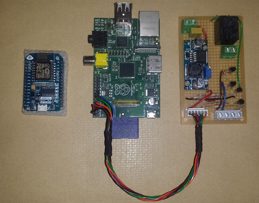
    I use a Raspberry Pi permanently installed inside the alarm panel with an ethernet connection to my router. I use the Pi to monitor the set/unset status and the alarm/silent status of my house alarm using digital GPIO on the Pi. I also have two of the Pi's GPIO setup as outputs one which is not curently assigned (just has a LED hanging off it for debugging) the other used to drive a relay, the NC contact is used on the fire alarm input to the panel which was originally bridged with a staple!

    Here's the Pi with the interface board which carries terminals, a DC-DC buck converter and a relay
    Shed_Alarm.jpg

    Originally I had a Python script running on the Pi which did pretty much one single job which I haven't seen mentioned here. It used the cURL tool from the Pi's command line to interface with Pushbullet's API to Push message my phone and browser (through a Chrome extension) with a message on alarm.

    I have since then done some interesting upgrades:
    * I have dropped the Python in favour of Node-RED (a fantastically easy to use yet powerful programming tool)
    * I have the garden shed as a wireless zone on my alarm using (Wemos D1 mini in Arduino IDE using MQTT over WiFi)

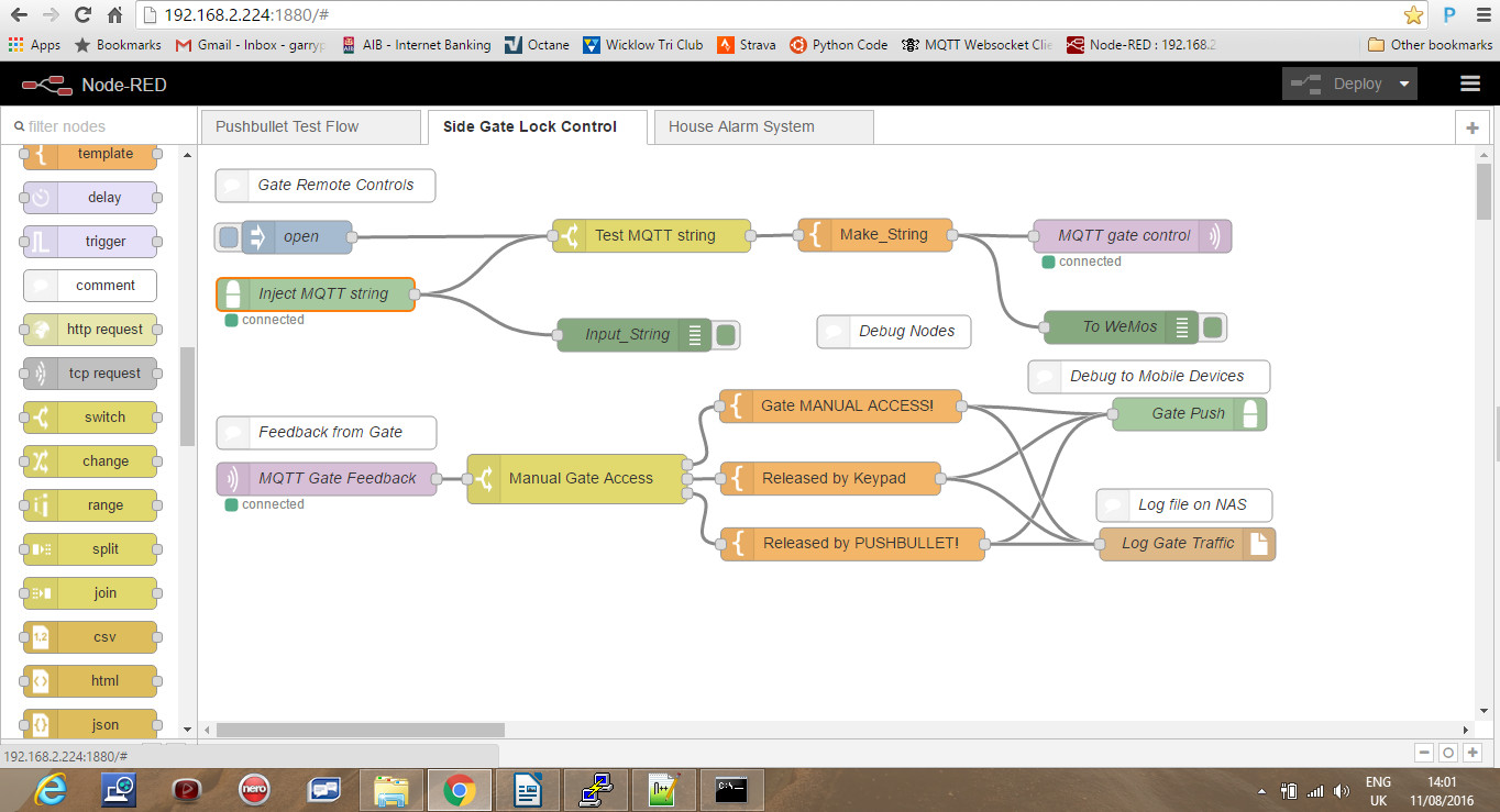
    Here's a Node-RED flow that shows the Pushbullet API input to the flow, an MQTT out command to a WiFi controller and some debugging/logging:
    NodeRed.jpg

    I now have a shed at the end of the garden which automatically sets/resets with the house alarm, which has a sound bomb siren of it's own and which triggers the house (fire) alarm if the shed is tampered with. The shed is solar powered with a battery which can run it for a few days with 12V led security lights and PIR sensor. The system uses a very neat user interface which is a collection of nodes in the Node-RED control flow hosted on the Pi. These are buttons, gauges and message fields which build a slick web/mobile interface. I have ported out the Node-RED through the home router firewall which allows me to monitor the whole system. I still use Pushbullet but now using Node-RED instead of cURL which is really easy and again I use a node in Node-RED to build logs on my NAS drive of pretty much everything that happens on the system; set, reset, alarm and even traffic through the side gate of the house.

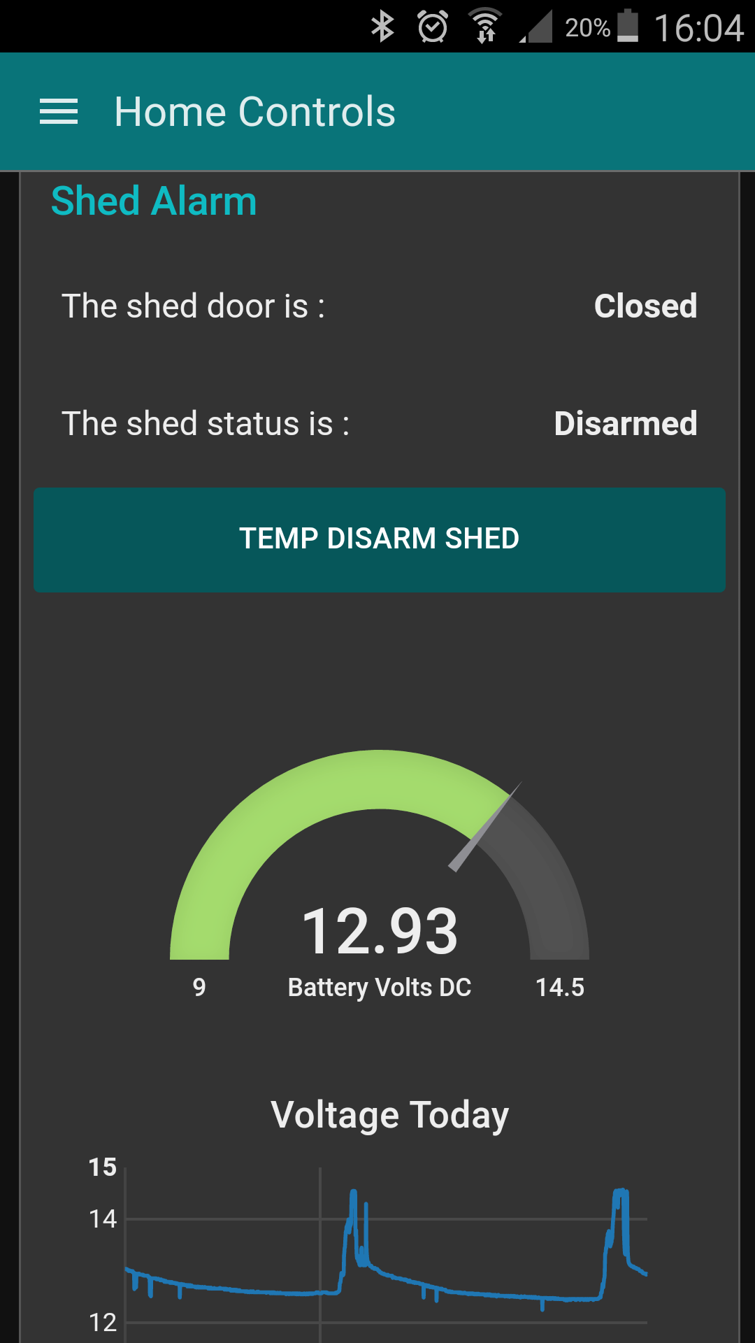
    This is part of what I have on my phone including analog read of the shed battery voltage and a trend:
    Screenshot_2016-12-01-16-04-36.png

    The temp disarm button allows me to lock and alarm the house then disarm the shed for 5 mins to access stuff or until the door closes for a couple of minutes at which point it resets. All of the communication over WiFi is done with MQTT which is super easy to use and has it's own background heartbeat/pinging with QOS settings and a Last Will & Testament function which allows me to log and see if any component goes offline.

    Having put Node-RED on the Pi to facilitate the alarm allowed me to stick ESP8266 based boards all over the house doing all sorts of things including a full on automated spook show at halloween with zombies in coffins with rattling covers, lightning and thunder in the house and a skeleton that appeared from nowhere. Why? Because it was so easy, everything in place!

    Hope that gives some inspiration

    Garry


  • Registered Users Posts: 32 mrkayak


    Garry,

    Great project! Thank you for sharing.
    I'm trying to arm/disarm my Aritech CS350 using NodeMCU digital output.

    Do you know how that should be wired?
    Would I need to connect the digital output pin to the input of a relay, and
    then wire the relay somehow to the Keyswitch input?

    Thanks.
    Best regards,
    Niall.


  • Registered Users Posts: 50 ✭✭GryKyo


    Hi Mrkayak.
    I have no personal experience with Aritech but this diagram is poached from one of ozmo's posts.

    291404.png

    If you look at the key switch circuit at the top of the circuit and imagine power across the two top/bottom terminals in this circuit you have the following scenarios:
    1. The circuit is complete through the C-NC contacts of the key switch. This means a short across the top resistor and a total of 4,700 ohms through the lower one.
    2. The circuit is complete through the two 4K7 resistors in series (9,400 ohms in total)
    3. The tamper contact is open so there is no circuit present

    Essentially this is a voltage divider circuit across an analogue input. I guess with the switch closed the system would disarm. Forcing a short across the top resistor gives let's say "most of" the analog input voltage to the input which the alarm can interpret as "Disarm". The current will follow the path of least resistence so will not even notice the top resistor.
    Opening the circuit through the key switch would divert the path of least resistance now through the two resistors in series which will now feed only a small voltage into the input. The alarm can interpret this as a "Set" command as this would be a "Fail to safe" condition. By this I mean that tampering with the key switch circuit (cutting it) will set the alarm as distinct from disarming, not desirable.
    The tamper contact will break the circuit completely so no voltage is present triggering a tamper condition and alarm activation.

    I own up here: I am not an alarm technician and I have no Aritech to test so it is entirely possible that the circuit has internal pull-up or some other arrangement. So my description above while it is likely to be correct in operation it may not be electrically, don't blow up your alarm and say it was my fault, please and thanks!

    If you have done some prototyping with your NodeMCU then you will know that the outputs are rated at 3.3Vdc and very low power, something like 20mA max so barely comfortable driving a bright LED. Trying to power a relay from this output will end up in a tiny smoke leak! What you need to do is find a transistor such as a 2N2222 or 2N3904, both of which I use all the time to drive relays. Both will be OK at 12V too making it easier to get a relay. These are NPN so can be put between your relay coil and ground as shown in the circuit below. You will have 12Vdc available in the panel so a standard automotive change over relay with a 12V coil would work. If you have an electrical wholesaler close they should be able to supply a relay on a base with screw terminals and using a 12V coil also, a bit easier to wire up.

    diodo_flyback_antiparallelo.jpg

    You drive one of the NodeMCU pins as an output and use this and a current limiting resistor of between 500 and 1K ohms between this output and the base pin of the transistor. This will stop the transistor from over loading the NodeMCU output circuit. Look at the diagram above which I found on line. Notice that there is a diode (standard low power rectifier type such as 1N40001 is mega cheap and easy to find) across the coil of the relay. This prevents the power in the coil dissipating back through your transistor when you switch off your relay. There is a spike of back emf through the circuit which will flow through the diode and spare your transistor.

    In operation your code on the NodeMCU will do as you wish to translate your remote arm/disarm request into a logic 1 or 0 on the output pin. You will have to try out your code using these circuits to work out which case causes your panel to arm or disarm, I can't help you here.

    Do post an update on here to let us know how it worked. My system is stable and dependable if a little close to the wire on solar charge in my garden shed at this time of the year. It is not an ideal situation either with a tree and buildings close enough. MQTT really is a reliable and easy protocol to use to communicate with your NodeMCU and there are libraries for most of the environments ported to the ESP8266 chip. The protocol is easy to use and in a case like this a single character can be enough to control your system.

    I had an alarm activation last Saturday which kicked off two push notifications and three emails and had me logged in to the CCTV cameras within 10 seconds with set, activation and reset logs all doing as they should. This has to be more dynamic than a monitor contract me thinks.

    Garry


  • Registered Users Posts: 3,853 ✭✭✭ozmo


    Exactly - the Aritech senses the sum value of the resistors in the key zone loop - one or two resistors controls it arming or disarming - no resistors (a short - or open circuit) and the tamper alarm sounds.
    So you would need source a relay module that is compatible with your nodeMCU that can switch in the above.

    “Roll it back”


  • Registered Users Posts: 32 mrkayak


    Ozmo and Garry,
    Thanks for detailed helpful responses!
    I'll try connecting a real switch (as per the diagram) and see if I can arm/disarm.  If that goes ok, then I can swap the switch for a relay.  In this yt-vid (v=YdTvItvhb5M), the nodeMCU is driving the relay module directly (ie without need for transistor circuit).
    Thanks!
    Best regards,
    Niall.


  • Advertisement
  • Registered Users Posts: 32 mrkayak


    Hi guys,

    still waiting on my order for nodeMCU ...

    In the meantime after a bit of research, it seems that the little
    relay module

    can be controlled directly by the GPIO output of the
    nodeMCU. I guess using just a relay would require the transistor
    circuit, but maybe the module has this built-in.

    https://github.com/tribaltronik/controlboard-nodemcu-switch

    I'll try it anyway, and report back.

    Thanks.
    Best regards,
    Niall.


  • Registered Users Posts: 50 ✭✭GryKyo


    @mrkayak:

    The GPIO pins of the NodeMCU are essentially wired directly to the ESP8266 module. These GPIO pins are rated at absolute max 12mA in source circuit (supplying 3.3v to a circuit) or 20mA sink (switching 3.3v max from your circuit to ground). There is obviously some internal circuitry with pull-up resistors etc which make the output spec different for both. The circuit I showed you in the earlier post with the 2N2222 transistor is "source" where 3.3V is being applied to the base of an NPN transistor. This circuit uses a transistor to do the heavy lifting, powering the coil of your relay.

    The relay modules that are sold for home automation, prototyping, arduino type circuits (all over eBay and Banggood) generally offer some isolation to protect your micro controller. By default the power used to drive the relay coil is from the NodeMCU GPIO pin but this module uses way more power than is available from the GPIO according to the spec sheet.
    Moving a jumper on the relay module selects an isolated input mode with external power supply. In this case the output of your NodeMCU is used to drive an optocoupler where the maximum load applied to the NodeMCU pin is the internal LED circuit of the optocouple. It isolates the remainder of your relay control circuit from the micro controller using a light bridge but this means you have to supply the power to the driven side of the optocouple and all of the electronics on the relay module separately. If you understand how a rely works with the magnetic field moving a contact to switch off/on then imagine the optocoupler as a LED pointing at a photo transistor where the LED light is used to switch the transistor on/off, your load being connected to the transistor.

    I did look at the youtube video and this guy has hooked up the relay module directly to the GPIO pin. It works, that is clear from the video. Being rated at a max current roughly in line with that taken to light the LED on the module it won't keep working for long! It is just in a different parish from it's comfort zone. The output of a NodeMCU is very unlikely to work with a 5V relay and the current to drive a 3.3v relay coil will very likely shorten the life of the ESP8266 chip considerably.

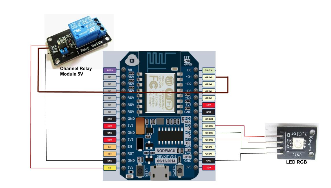
    I also looked at the project on GitHub and notice that the relay module is connected to the 5V pin of the NodeMCU. You should note that this pin is the input voltage supplied to the board through the USB connection, wired directly to this pin. You can alternatively supply (max) 5V to the NodeMCU via this pin if you are not using a USB cable. This supply voltage is then regulated by the on board linear regulator to 3.3V which is the voltage that the ESP8266 module can tolerate.

    ControlBoardNodeMCUSwitch.jpg

    I would suggest if you have ordered your NodeMCU on line and you are used to searching and finding electronic stuff then shop for some beginner electronic assortments. You may only use 10% of the items but when you need a 1k resistor or a NPN transistor NOW, then they are worth it!

    I do suggest that in terms of:
    • Easily locating a suitable relay to replace the keyswitch in the earlier drawing
    • Interposing with the alarm panel voltage (Normally 12Vdc)
    • Building a robust interface between your ESP8266 and your alarm
    • Having peace of mind knowing that nothing is creaking in the red-zone...

    ...the circuit where the NodeMCU drives a transistor with a current limiting resistor checks all of these questions. Where on this land does mrkayak live?

    Garry


  • Registered Users Posts: 174 ✭✭maurice1


    On the Aritech you set up the keyswitch in the menu.

    Key Zone Attributes Key Zone Attributes
    Fs Full set. Keyswitch fully arms system.
    P1 Partguard 1. Keyswitch partially arms system using Partguard 1.
    P2 Partguard 2. Keyswitch partially arms system using Partguard 2.
    Us Unset. Keyswitch disarms system.
    Pu Pulse. Keyswitch used must be a pulse type.
    Allows arming/disarming with multiple keyswitches in a system.
    Qs Quick set. Keyswitch arms panel without exit time.

    Wiring wise it is a zone with 2 x 4.7k resistors

    I di format the text above with spaces but its gone


  • Registered Users Posts: 32 mrkayak


    GryKyo wrote: »
    @mrkayak:

    The GPIO pins of the NodeMCU are essentially wired directly to the ESP8266 module. These GPIO pins are rated at absolute max 12mA in source circuit (supplying 3.3v to a circuit) or 20mA sink (switching 3.3v max from your circuit to ground). There is obviously some internal circuitry with pull-up resistors etc which make the output spec different for both. The circuit I showed you in the earlier post with the 2N2222 transistor is "source" where 3.3V is being applied to the base of an NPN transistor. This circuit uses a transistor to do the heavy lifting, powering the coil of your relay.

    The relay modules that are sold for home automation, prototyping, arduino type circuits (all over eBay and Banggood) generally offer some isolation to protect your micro controller. By default the power used to drive the relay coil is from the NodeMCU GPIO pin but this module uses way more power than is available from the GPIO according to the spec sheet.
    Moving a jumper on the relay module selects an isolated input mode with external power supply. In this case the output of your NodeMCU is used to drive an optocoupler where the maximum load applied to the NodeMCU pin is the internal LED circuit of the optocouple. It isolates the remainder of your relay control circuit from the micro controller using a light bridge but this means you have to supply the power to the driven side of the optocouple and all of the electronics on the relay module separately. If you understand how a rely works with the magnetic field moving a contact to switch off/on then imagine the optocoupler as a LED pointing at a photo transistor where the LED light is used to switch the transistor on/off, your load being connected to the transistor.

    I did look at the youtube video and this guy has hooked up the relay module directly to the GPIO pin. It works, that is clear from the video. Being rated at a max current roughly in line with that taken to light the LED on the module it won't keep working for long! It is just in a different parish from it's comfort zone. The output of a NodeMCU is very unlikely to work with a 5V relay and the current to drive a 3.3v relay coil will very likely shorten the life of the ESP8266 chip considerably.

    I also looked at the project on GitHub and notice that the relay module is connected to the 5V pin of the NodeMCU. You should note that this pin is the input voltage supplied to the board through the USB connection, wired directly to this pin. You can alternatively supply (max) 5V to the NodeMCU via this pin if you are not using a USB cable. This supply voltage is then regulated by the on board linear regulator to 3.3V which is the voltage that the ESP8266 module can tolerate.

    ControlBoardNodeMCUSwitch.jpg

    I would suggest if you have ordered your NodeMCU on line and you are used to searching and finding electronic stuff then shop for some beginner electronic assortments. You may only use 10% of the items but when you need a 1k resistor or a NPN transistor NOW, then they are worth it!

    I do suggest that in terms of:
    • Easily locating a suitable relay to replace the keyswitch in the earlier drawing
    • Interposing with the alarm panel voltage (Normally 12Vdc)
    • Building a robust interface between your ESP8266 and your alarm
    • Having peace of mind knowing that nothing is creaking in the red-zone...

    ...the circuit where the NodeMCU drives a transistor with a current limiting resistor checks all of these questions. Where on this land does mrkayak live?

    Garry


    Hi Garry,

    Thanks for all your help with this. It took ages to get nodeMCU, etc. So long that I ended up doing another project to control an
    extractor fan in the bathroom based on humidity readings from a DHT22 sensor. Everything was working fine .. but as you
    so helpfully pointed out the nodeMCU doesn't have enough power to switch the relay properly. It can turn the relay on and off,
    but not while it's WiFi connected .. and reading DHT sensor at the same time :)
    So now I will work on the transistor circuit to control the relay. My plan is to work on the alarm project as soon as I'm
    finished this one.
    Thanks again.

    Best regards,
    Niall.


  • Registered Users Posts: 11 conor o brien


    ozmo wrote: »
    Thanks :) PM Sent.

    Hi Ozmo, Just came across this thread, Looks like you done some great work,
    Could i also get a look at your HKC docs.
    Thanks


  • Registered Users Posts: 3,853 ✭✭✭ozmo


    Hi Ozmo, Just came across this thread, Looks like you done some great work,
    Could i also get a look at your HKC docs.
    Thanks

    Thanks - Sure - Ill send on:

    Some updates:
    Fixed: There was an issue reported with the blinking keypad lights HKC can optionally do at Part-set being misinterpreted as an alarm - this is fixed in the latest code.

    “Roll it back”


  • Registered Users Posts: 3,853 ✭✭✭ozmo


    Oh - and most the parts can be bought on Adverts.ie so you dont have to wait weeks to arrive from China - eg. here is the power supply module for 3 euros:
    http://www.adverts.ie/other-electronics/lm2596s-dc-dc-adjustable-step-down-power-supply-module/9024399

    “Roll it back”


  • Registered Users Posts: 11 conor o brien


    Thanks for this, my goal is to try and apply what you have done to esp8266 based module and a HKC 1070.
    Great to know about the stuff on adverts as well.
    Thanks again.:)


  • Registered Users Posts: 227 ✭✭bibibobo


    Pics of my HKC alarm interface which I thought about implementing for nearly a year. The design changed a few times in my head and I have eventually arrived at this design. I was going to add a GSM dialler e.g. SIM900A/SIM800L but I have abandoned that for now. Working very well for nearly a month now.

    Electronics used:
    Wemos D1 mini ESP8266 €2.18 on aliexpress
    DC-DC convertor €0.60
    Quad optoisolator (PC847 or four PC817) €0.40
    2k resistors (<€0.05)
    Miscellaneous connectors, wire, board <€2

    Features:
    1. Publishes change in output status to MQTT. GPIO inputs are debounced at 50ms.
    2. Publishes to MQTT at various intervals; RSSI signal strength, status of all panel outputs, clientid on boot (from mac address)
    3. Interfaces to Node-red server to send emails via gmail node and SMS txts via Twilio node on change in panel outputs or alarm activations.
    4. Reconnects on loss of wifi or link to MQTT server.
    5. Allows OTA updates for easy development changes from the desk.

    Anybody interested in the arduino code can pm me.


  • Registered Users Posts: 50 ✭✭GryKyo


    Looks good!
    This is very similar to what I have done in our home alarm where I too use MQTT and Node-RED. You must have a MQTT server or service set up so there are more options open to you.

    Remote set/reset and monitor of other buildings such as garage/shed.

    This was the second reason I upgraded mine along side monitoring and notification. If you are using GPIO's from the panel to know when the system is set or not then an other D1Mini in your garage or shed also talking to your Node-RED flow via MQTT and you can secure this also. I found that my alarm panel had an input circuit for a fire alarm system but the installer had bridged across the input with a staple. I was able to put an opto-isolated relay on my Raspberry Pi GPIO (I have one of these in the panel interfaced (both input/output) with the panel's GPIO) which is where my MQTT broker and NodeRed are running.
    I publish the alarm panel status on MQTT when it sets/resets so the other D1 Minis I have then enable/disable the reed switches and PIR sensors on their GPIO. They then publish if there is an "intrusion" and the house alarm is triggered via the fire alarm circuit.

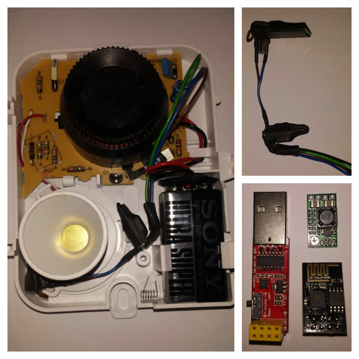
    I have recently modified a regular €10 smoke alarm which is in my attic space to include a mini DC-DC buck converter with an enable pin which when enabled by the smoke alarm boots up an ESP01 module. This connects via MQTT to also trip the fire alarm circuit and send me a push message via Pushbullet.

    FYI there is a Pushbullet node in Node-RED which will instantly push a notification to your phone and if enabled an extension of Google Chrome browser. Let me know if you would like parts links, schematics or code for any of these accessories?

    Garry


  • Advertisement
  • Registered Users Posts: 227 ✭✭bibibobo


    Hi, I saw your project also. Very interesting and similar tools used. I have a Raspberry pi 2 running mosquitto and node-red for various MQTT, Sonoff S20 wifi sockets, gasboiler controller, doorbell disabling, temperature, pressure monitoring etc etc. It has been very reliable for over a year now. This guys blog and script is great for getting started ... I'll leave the link here for other techy types to follow if they want. https://tech.scargill.net/a-christmas-script/.

    I briefly looked at using pushbullets for another project but gave up very quickly. I would love to try it. Any chance of pm'ing your flow code for analysis?

    Am very interested in how you connected the ESP01 to the smoke alarm though I'm not sure my alarm panel (HKC SW8/12) has a fire alarm input. Still I could just publish to MQTT and manipulate in node-red direct.

    D


  • Registered Users Posts: 205 ✭✭Bazsutto


    bibibobo wrote: »
    Pics of my HKC alarm version which I thought about implementing for nearly a year. The design changed a few times in my head and I have eventually arrived at this design. I was going to add a GSM dialler e.g. SIM900A/SIM800L but I have abandoned that for now. Working very well for nearly a month now.

    Electronics used:
    Wemos D1 mini ESP8266 €2.18 on aliexpress
    DC-DC convertor €0.60
    Quad optoisolator (PC847 or four PC817) €0.40
    2k resistors (<€0.05)
    Miscellaneous connectors, wire, board <€2

    Features:
    1. Publishes change in output status to MQTT. GPIO inputs are debounced at 50ms.
    2. Publishes to MQTT at various intervals; RSSI signal strength, status of all panel outputs, clientid on boot (from mac address)
    3. Interfaces to Node-red server to send emails via gmail node and SMS txts via Twilio node on change in panel outputs or alarm activations.
    4. Reconnects on loss of wifi or link to MQTT server.
    5. Allows OTA updates for easy development changes from the desk.

    Anybody interested in the arduino code can pm me.

    Nice project. My arduino is hardwired to my network. I purchased a Wemos a good while back and haven't got round to messing around with it to get familiar with. I have the Sim800L as part of my system. As you outlined, a separate PSU is required to power. I used a 2A 5V AC/DC step-down converter ($4 on banggood). Only drawback is it only runs on mains so not active during power cut . Running reliably for over a year now (more reliable than email notifications).

    Gary's post this time last year got me thinking about alarming the shed. As I didn't have a wireless access point for my system I just modified a 12V RF transmitter purchased on banggood for $7 and used a second arduino in shed. Powered it with alarm battery and solar panel. Worked great in summer, but had to upgrade battery to car one for these dark days of winter.

    I would like to try the Wemos and node-red for this in the future.


  • Registered Users Posts: 50 ✭✭GryKyo


    I will come back to you with flows for Node-RED, I have to look and see if I export my flows do I export my paths, passwords etc for API's, Emails etc... security.

    For the moment, a picture speaks a thousand words. Here is an image of the parts in the smoke alarm.

    Smoke_Alarm_Parts.jpg

    It uses an ESP-01 verson of the ESP8266 chip which you can see in the image with a USB to serial adaptor. Hint: If you are buying a programmer, get one with a switch to pull GPIO to GND at power up. This puts the chip in to flashing mode so a program can be uploaded.

    The other PCB in the frame with the ESP-01 is a tiny little DC to DC buck converter. It has solder pads on the rear which allow you to select a fixed voltage (all the popular dc voltages from 0-12 including 3.3V). As supplied it is on the pot adjuster but only needs a track cut and blob of solder to fix voltage.

    Most of the smoke alarms use a standard control IC which generally has a GPIO pin. If your smoke alarm doesn't have an output to daisy-chain to other alarms as sounders then you can probe the circuit and find the pin. In my alarm found at the check out of Woodies there is a pin with no connection which jumps to 9Volts when the alarm sounds. I use this with a small resistor, about 330ohm if I remeber right to pull the "enable" pin of the buck converter high. This turns on the 3.3V supply to the ESP-01 module which then runs a simple sketch.

    As long as the alarm is sounding and the power is supplied to the ESP-01 it connects to the WiFi (I use a static IP as it is considerably faster and more reliable to connect). Once it establishes WiFi it pushes a message to my phone via Pushbullet and MQTT to Node-RED. I can use this to trigger the fire alarm circuit on the house alarm; the hope being if there was a fire when we weren't home somebody's attention might be drawn to the house. The fire alarm sounds on/ff with intervals of about 10 seconds so sounds a bit odd.

    I can send the sketch by PM if anybody wants to see how it works. It uses the WiFiManager library so will setup a "hot spot" and webserver and host a config web page to allow a user to input new WiFi creds.


  • Registered Users Posts: 3,853 ✭✭✭ozmo


    I too have been looking at the ESP platform... and have have some good success with porting the Aritech Keypad Emulator code over to the ESP32 Chip.

    I'm using this little $9 open source board (D-duino-32) which has a tiny display built in... but any ESP32 should work.

    Benefits of this over the Arduino, is as well as built in WiFi - is lots more space to implement better web pages and https connections.
    It also has bluetooth built in which could have interesting possibilities...

    Progress so far - Its connecting well to the Aritech 4 wire keypad bus and is updating the the keypads display to its little screen... :)

    6ppwys.jpg

    And by emulating a CD9038 Keypad this time - you will get a few more zones to use in the system
    that can be triggered by things connected to the the ESP32... :D

    “Roll it back”


  • Registered Users Posts: 50 ✭✭GryKyo


    ozmo wrote: »
    I too have been looking at the ESP platform... and have have some good success with porting the Aritech Keypad Emulator code over to the ESP32 Chip.

    I'm using this little $9 open source board (D-duino-32) which has a tiny display built in... but any ESP32 should work...

    Cool!
    I have a couple of those boards too, branded Wemos LoLin ESP32... but don't own an Aritech! That said I'm keen to follow your progress.

    Lots of stuff to explore yet, Bluetooth as you say but lots of I/O, multi analogs, touch, separate CPU's, really deep sleep etc but that's taking this thread on a tangent!


  • Registered Users Posts: 2 makkie2002


    Nice work Ozmo!

    I also have some ESP32 lying around. It would be instructive to get some more information on how you did this (including the source code :) ).

    ozmo wrote: »
    I too have been looking at the ESP platform... and have have some good success with porting the Aritech Keypad Emulator code over to the ESP32 Chip.

    I'm using this little $9 open source board (D-duino-32) which has a tiny display built in... but any ESP32 should work.

    Benefits of this over the Arduino, is as well as built in WiFi - is lots more space to implement better web pages and https connections.
    It also has bluetooth built in which could have interesting possibilities...

    Progress so far - Its connecting well to the Aritech 4 wire keypad bus and is updating the the keypads display to its little screen... :)


    And by emulating a CD9038 Keypad this time - you will get a few more zones to use in the system
    that can be triggered by things connected to the the ESP32... :D


  • Registered Users Posts: 116 ✭✭freddy99


    Does anyone have the arduino system working reliably with an Aritech 350?
    When I trialed it, it gave keypad fault issues every couple of weeks which could not be reset remotely. I’d love to have this running, or even a raspberry Pi equivalent.
    Thanks.


  • Registered Users Posts: 3,853 ✭✭✭ozmo


    makkie2002 wrote: »
    Nice work Ozmo!

    I also have some ESP32 lying around. It would be instructive to get some more information on how you did this (including the source code :) ).

    Took a break over christmas and didnt manage to continue back on it - I can send on my progress to anyone who wants to have a look - I had the wifi and all the aritech side of the comms done - it now needs the webserver side to be ported to the esp32 wifi libraries - wifi libraries work differently to the lan libraries - the advantage of the esp32 is that you dont need an ethernet card and you have lots more space for better html - plus should be able to do https.
    freddy99 wrote: »
    Does anyone have the arduino system working reliably with an Aritech 350?
    When I trialed it, it gave keypad fault issues every couple of weeks which could not be reset remotely. I’d love to have this running, or even a raspberry Pi equivalent.
    Thanks.

    This is one aritech I don't have a sample board for... but if I see anything that could cause it when porting the above Ill let you know.

    “Roll it back”


  • Registered Users Posts: 2 makkie2002


    ozmo wrote: »
    Took a break over christmas and didnt manage to continue back on it - I can send on my progress to anyone who wants to have a look - I had the wifi and all the aritech side of the comms done - it now needs the webserver side to be ported to the esp32 wifi libraries - wifi libraries work differently to the lan libraries - the advantage of the esp32 is that you dont need an ethernet card and you have lots more space for better html - plus should be able to do https.

    I want to have look !
    I assume the hardware side requires always some electronics to get to the correct voltage levels (esp32 = 3.3V)?


  • Advertisement
  • Registered Users Posts: 2 conor_murphy


    I've been looking at using a ESP32 to provide an interface to a HKC SW8/12.

    The plan is for the ESP32 to provide a COAP interface and use a Pi running OpenHAB to provide the user interface.

    Ozmo, is there much work involved in porting the code you had for the HKC SW8/12 over to the ESP32?

    Thanks,
    Conor


Advertisement