Advertisement
If you have a new account but are having problems posting or verifying your account, please email us on hello@boards.ie for help. Thanks :)
Hello all! Please ensure that you are posting a new thread or question in the appropriate forum. The Feedback forum is overwhelmed with questions that are having to be moved elsewhere. If you need help to verify your account contact hello@boards.ie
Hi all! We have been experiencing an issue on site where threads have been missing the latest postings. The platform host Vanilla are working on this issue. A workaround that has been used by some is to navigate back from 1 to 10+ pages to re-sync the thread and this will then show the latest posts. Thanks, Mike.
Hi there,
There is an issue with role permissions that is being worked on at the moment.
If you are having trouble with access or permissions on regional forums please post here to get access: https://www.boards.ie/discussion/2058365403/you-do-not-have-permission-for-that#latest
There is an issue with role permissions that is being worked on at the moment.
If you are having trouble with access or permissions on regional forums please post here to get access: https://www.boards.ie/discussion/2058365403/you-do-not-have-permission-for-that#latest
Aritech Alarm Internet Dialler
Comments
-
I did thanks - and the hardware might be a little too weird to do that one though. The signal and power share the only two wires - this would make any keypad emulator more complex to make compatible electronics wise. I will keep it mind though once I finish the hkc though. cheers.
Did you ever get anywhere with the astec alarm monitoring?0 -
Would it be possible to do all this using a Raspberry Pi only (and not the arduino?). I am an experienced python programmer but am not an expert in the electrical side of things I will admit!
I already have a Raspberry Pi and have converted 'tnegun's perl script to python and to use PushBullet instead of Email.
https://gist.github.com/fbradyirl/b8614554822e39a323cd1f7daafa5a36
I would love to get the dialler working also on the Pi. I wonder what kind of cables, etc I would need to connect the pi to the panel?0 -
I did look - but the non standard display looked a lot of work to implement in html and the electrical interface to the Arduino would need something special with the power going over the data lines - one option might be to use the electronics from an existing sensor? If I ever come across a sensor the panel I might try that.Did you ever get anywhere with the astec alarm monitoring?Would it be possible to do all this using a Raspberry Pi only (and not the arduino?).... I wonder what kind of cables, etc I would need to connect the pi to the panel?
It likely not possible with an RPI as the timing is very critical, especially using a high level language like python - the Arduino has only a few milliSeconds to respond to a message from the alarm panel or it gives up waiting and goes off and does something else, but as the Arduino is only running the one program it can be sure to do it in time.
With Raspberry Pi you have so much running on it interrupting the main code fighting for cpu time that you cannot guarantee a low latency(ie. prompt) realtime response with no pauses, even if it is faster.“Roll it back”
0 -
Underwurlde wrote: »...I was going to create a very simple version (using a GSM shield) that will text me when the alarm goes off.....As this is almost 14v, I would need some sort of voltage divider to bring the voltage down.
Can you advise ... The recommended values for the voltage divider resisters
& The best way to hook this to the Arduino
Thanks for any help you can offer.
Thanks for the comments - sorry I didnt reply sooner.
Yes that sounds like a good plan - The Outputs are indeed a high 14v aprox so you would need something to bring the voltage down - you could use two resistors (high values maybe 10K and 4.7K with the arduino input pin and gnd connected across the 4.7K resistor) - just make sure the voltage is definitely less than 5v - but another option here might be to use a Relay on the Internal Siren pins..“Roll it back”
0 -
I did look - but the non standard display looked a lot of work to implement in html and the electrical interface to the Arduino would need something special with the power going over the data lines - one option might be to use the electronics from an existing sensor? If I ever come across a sensor the panel I might try that.
It likely not possible with an RPI as the timing is very critical, especially using a high level language like python - the Arduino has only a few milliSeconds to respond to a message from the alarm panel or it gives up waiting and goes off and does something else, but as the Arduino is only running the one program it can be sure to do it in time.
With Raspberry Pi you have so much running on it interrupting the main code fighting for cpu time that you cannot guarantee a low latency(ie. prompt) realtime response with no pauses, even if it is faster.
Yeah I see what you are saying.
Do you have any pointers on how you went about figuring out how to simulate the keypad bus and reads? I'd like to have a play around with it see if I can learn something.0 -
Advertisement
-
Been reading through all the posts and a lot of hours have been spent putting that together. I was curious to see if you were familiar with the GE ITI Concord International panel. A mainly wireless board installed by Phonewatch, in my case, in 2007. From what I can see there's no serial/printer port that can be tapped into so I was wondering if you have had a chance to test your build on this particular panel.0
-
Do you have any pointers on how you went about figuring out how to simulate the keypad bus and reads?
I used an DSO (digital storage oscilloscope) to determine the baud rate and voltage levels of the keypad data wire - It was obvious it was standard Uart Rx/Tx protocol, just an odd baudrate and odd number of bits - I connected the comms using a resistor bridge to drop the voltage - and wrote a program on the Arduino to dump everything it could see on the data bus as hex and ascii (code is still there commented out)- I could see packets of data but I couldn't be sure what device was 'speaking' as the HKC uses the one wire shared with all devices- so I used a resistor on the keypad tx so I could see by the lower voltage level if the messages were coming from the Keypad or the panel. The RKP file in the code has examples of this data I captured.
The messages I could see all were a similar format as expected- a header byte(used to target a message to a specific device), a command byte(eg. display this on the screen, or play that tone on the keypad speaker), followed by data (message to display) - and lastly a checksum (sum of all the data in the packet mod 256)
The tricky part was determining what each command did and what response was required of it.
I later acquired a Logic Analyzer which does a similar job to the arduino program - I was able to more accurately capture the timings also from the real response from a keypad (see below for a screenshot) and compare it to a capture of my hardware and continually update my code so my hardware would always reply with the exact same response with the same delays as the real keypad.
The HKC comms are different to the Aritech in that each byte is 9 bits rather than the more normal 8. The 9th bit is set on the first byte of the message which makes it easy for any hardware to know when the message starts.
http://i65.tinypic.com/1z3mhb7.png
You can see in this screenshot how the DA displays the signal as well its decoded value in Hex and Ascii. This message is a response to a ping (command 0) from a keypad to panel - FF means there are no key-presses to report 8E is the checksum. Top trace is the Real Keypad - middle is my hardware's response - you can see they are identical.
I documented all the commands in detail that I needed to use in the source code (again in the RKP class).
Hope that helps...retepnosnikta wrote: »Been reading through all the posts and a lot of hours have been spent putting that together. I was curious to see if you were familiar with the GE ITI Concord International panel.
Thanks for the comments -
I don't have access to one of those - as every alarm panel brand uses different data protocols it would require me to analyse the traffic on the keypad of one such device for me to make the project compatible with another range of panels.“Roll it back”
0 -
I used an DSO (digital storage oscilloscope) to determine the baud rate and voltage levels of the keypad data wire - It was obvious it was standard Uart Rx/Tx protocol, just an odd baudrate and odd number of bits - I connected the comms using a resistor bridge to drop the voltage - and wrote a program on the Arduino to dump everything it could see on the data bus as hex and ascii (code is still there commented out)- I could see packets of data but I couldn't be sure what device was 'speaking' as the HKC uses the one wire shared with all devices- so I used a resistor on the keypad tx so I could see by the lower voltage level if the messages were coming from the Keypad or the panel. The RKP file in the code has examples of this data I captured.
The messages I could see all were a similar format as expected- a header byte(used to target a message to a specific device), a command byte(eg. display this on the screen, or play that tone on the keypad speaker), followed by data (message to display) - and lastly a checksum (sum of all the data in the packet mod 256)
The tricky part was determining what each command did and what response was required of it.
I later acquired a Logic Analyzer which does a similar job to the arduino program - I was able to more accurately capture the timings also from the real response from a keypad (see below for a screenshot) and compare it to a capture of my hardware and continually update my code so my hardware would always reply with the exact same response with the same delays as the real keypad.
The HKC comms are different to the Aritech in that each byte is 9 bits rather than the more normal 8. The 9th bit is set on the first byte of the message which makes it easy for any hardware to know when the message starts.
http://i65.tinypic.com/1z3mhb7.png
You can see in this screenshot how the DA displays the signal as well its decoded value in Hex and Ascii. This message is a response to a ping (command 0) from a keypad to panel - FF means there are no key-presses to report 8E is the checksum. Top trace is the Real Keypad - middle is my hardware's response - you can see they are identical.
I documented all the commands in detail that I needed to use in the source code (again in the RKP class).
Hope that helps...
Thanks for the comments -
I don't have access to one of those - as every alarm panel brand uses different data protocols it would require me to analyse the traffic on the keypad of one such device for me to make the project compatible with another range of panels.
I thought so. I only have one Concord panel and it's currently mounted as part of my alarm system. Hopefully someone may have a spare panel they could donate to you for analysis. I would imagine it will pose the greatest challenge of all.
Once again great work. It's very educational and interesting to see the different results you achieve.0 -
@fbradyirl
I changed from an arduino to a rasp pi1B+ because it is easier to programme by winscp and putty, rather than disconnecting the arduino and plugging it into the usb every time I got inspiration.
I bought 3 x mcp3008 analogue to digital converters and connected them to the Rpi.
Using 19 of the 24 analogue inputs on the MCP3008 s I connected the
10 zones (On aritech Panel 0 - 5vdc)
4 outputs (On aritech Panel 0 - 5vdc)
2 bell (On aritech Panel 0 - 12vdc)
1 doorbell
1 pressure on water mains ( If value drops too much I have a leak)
1 pressure on boiler if it drops below 1 bar, I get an email
by voltage bridge divider using resistors to the MCP inputs, if my calculations were wrong I only ruined the MCP3008.
Did most of the scripts in python, using rpi.gpio.
When a circuit is open the MCP gives a value of ~900/1023, when it is closed gives a value of late ~600/1023.
So my programme looks when the value
if 850 <= Entry/Exit <= 1024: T8 = 0 # Alarm Open = 900
else: T8 = 1 #Normally Closed = 700
The hall door sends an email every time it opens to keep it alive, (may not be necessary).
A text is sent via voipcheap when int or ext siren are low sending me a sms of which zone activated and value and sends another if there is a change.
For instance:
if the value = 851 = a truck going by
if the value = 999 = window smashed.
Another handy thing about the pi is I can change the programme from anywhere by VPN.
I also use 2xMCP23017 (32 digital outputs/inputs) to control a relay board for lights, Under floor heating zones and solar pump. If the alarm goes off the lights come on.
The remaining GPIOs are for the water meter and flow meter on Solar panel, 2 x esb meters and about a dozen DS18b20 to read temp and graph output, All that using about 9 gpio pins.
If you do decide to make a veroboard shield for the pi, I made the mistake of ordering headers that were too short and wouldn't fit with the height of the MCPs and the components on the pi. Did try a rpi3 but got very warm so i stuck with the pi1
I still like my arduino for running the 433 mhz transmitter for the remote sockets you buy from powercity, but I couldn't get the arduino to send texts and emails0 -
retepnosnikta wrote: »Been reading through all the posts and a lot of hours have been spent putting that together. I was curious to see if you were familiar with the GE ITI Concord International panel. A mainly wireless board installed by Phonewatch, in my case, in 2007. From what I can see there's no serial/printer port that can be tapped into so I was wondering if you have had a chance to test your build on this particular panel.
It could be tapped into through the keypad bus.
Have not done it myself but its a communication path to the system.0 -
Advertisement
-
-
It could be tapped into through the keypad bus.
Have not done it myself but its a communication path to the system.
Looks like it would be possible to tap in on the terminals on the keypad module. Red+12 , Black gnd, green bus A, white bus B. I reckon the problem will be trying to identify the protocol between the keypad and the control panel. GE equipment is extremely proprietary and I can find little or no info on the web about it.
Going the keypad route, I'm trying to identify Ozmo's final hardware requirements and associated wiring plan. There's a lot changes and modifications made through this rather long topic. Could anyone point me to the final solution so I can get cracking and test this panel out.
This is a perfect "How To" sticky that could be amended as and when working solutions for any new panels are up and working.0 -
I know this question may sound irrelevant but if I decided to power the Uno with an independant 5v power supply, besides the Uno and the Ethernet Shield, what other components would I need to connect to the panel's keypad. Obviously 12v and Gnd are not required and I'm figuring that Bus A and Bus B on the keypad could be transmit/receive. This is purely just guesswork.0
-
retepnosnikta wrote: »I know this question may sound irrelevant but if I decided to power the Uno with an independant 5v power supply, besides the Uno and the Ethernet Shield, what other components would I need to connect to the panel's keypad. Obviously 12v and Gnd are not required and I'm figuring that Bus A and Bus B on the keypad could be transmit/receive. This is purely just guesswork.
Ozmo after a little more searching I came across this info which may be of use. It looks like the bus is using RS485 protocol. Again it way beyond my "pay grade" but I'm sure you will be able to make sense of it.
http://www.avrfreaks.net/forum/ge-security-panel-superbus-2000-protocolrs485-ethernet0 -
retepnosnikta wrote: »Ozmo after a little more searching I came across this info which may be of use. It looks like the bus is using RS485 protocol. http://www.avrfreaks.net/forum/ge-security-panel-superbus-2000-protocolrs485-ethernet
Good find - for your GE Panel, it may be that the keypad uses an rs485 protocol - but it may also be just an optional automation addon like this (link) that adds rs485 capability maybe? but worth following up?
If it is RS485, then the electronic circuit part of the project can be bought quite cheaply to connect it to the Arduino.
Don't try connecting the Arduino directly to these terminals without the correct electrical adapter - Arduino can only take 0 to 5v, and some of these interfaces are usually higher and sometimes even can go negative.
There is a guy on adverts that sell RS485 Arduino adapters for 3 Euros - (link). dx.com have them as well.
If you are unfamilar with Arduino programming, you could also buy a pc rs485 card 4 euros (link) and use standard pc software (eg. termite) to capture some packets off the wire.
Without a scope - You will have to guess the baud rate - but you could be lucky and its a common one like 9600 or 19200.
That's the hardware - you will still need write the software to decode and use the information, that will be a tougher task - Let us know if you do manage to capture any of the bus traffic and we can see if its possible to decode it.“Roll it back”
0 -
Good find - for your GE Panel, it may be that the keypad uses an rs485 protocol - but it may also be just an optional automation addon like this (link) that adds rs485 capability maybe? but worth following up?
If it is RS485, then the electronic circuit part of the project can be bought quite cheaply to connect it to the Arduino.
Don't try connecting the Arduino directly to these terminals without the correct electrical adapter - Arduino can only take 0 to 5v, and some of these interfaces are usually higher and sometimes even can go negative.
There is a guy on adverts that sell RS485 Arduino adapters for 3 Euros - (link). dx.com have them as well.
If you are unfamilar with Arduino programming, you could also buy a pc rs485 card 4 euros (link) and use standard pc software (eg. termite) to capture some packets off the wire.
Without a scope - You will have to guess the baud rate - but you could be lucky and its a common one like 9600 or 19200.
That's the hardware - you will still need write the software to decode and use the information, that will be a tougher task - Let us know if you do manage to capture any of the bus traffic and we can see if its possible to decode it.
Just pm you Ozmo. May help in some way.0 -
Was looking through the code and done a Wiki on SHA-1 and seen the following:Microsoft,[7] Google[8] and Mozilla[9][10][11] have all announced that their respective browsers will stop accepting SHA-1 SSL certificates by 2017.
I know its a bit away yet, but would this suggest that you won't be able to remote login using these browsers from 2017 without updating the code?0 -
SHA-1?
Thanks for the heads up - Its a good question and Ive checked into it but my understanding is this browser change will not affect the websocket protocols - Ill keep and eye out for confirmation of this and update the code if there is any new recommended way of doing things - but as of now websockets are not affected and will continue to use sha-1“Roll it back”
0 -
@tnegun
yea the Aritech works as it always works.
The Rasp pi through the mcp3008 just read the values of the zones.
Or to put it another way,
Each Zone has 2 wires with an End Of Line resistor in the last detector in the circuit like most alarm panels.
One wire is ignored (ground) and the other is +Vdc, So I just connected 16 wires from the +Vdc to the mcp3008s which is also in the panel
Every second Pi reads 3008s and if the int siren is high and there is a change it sends me an sms. If your panel has a keyswitch facility you could have a relay from the pi to reset the alarm if you wanted. I don't know if you could do Osmo's cool keypad replicator on a pi
Elec meters, lights are read by pulse meter in link above and the other loads are read by 50Amp bigger version, The same Rpi creates graphs of usage,
The water meter is graphed also using a GPIO and https://www.bes.co.uk/products/102.asp#13766.
I know the Pi seems complicated to start with but it can do so much if u have used a soldering iron and some veroboard.
@Ozzo, I read your castle code and well done for getting it working.
Another reason I went pi was that UPC told me they were turning off the SMTP server and I know arduino couldn't do email without SMTP. That may have changed now.0 -
As I don't have an engineer code for my system, I'm working on a much simpler solution where I check to see if there's a voltage on the siren outputs and send an SMS if there is. I can see that there is 13.7 volts here when the alarm is on so I created a voltage divider to bring the voltage down below 5 volts so as not to damage the Arduino (10K/4.7K). When testing (using just a battery to simulate the siren going on), my solution does everything I planned. However now when I try to hook it up to the panel, as soon as I connect the wires to the siren connectors, the siren goes off (possibly some sort of tamper mechanism). Any ideas on how I can monitor this without it interfering with the alarm operation?0
-
Advertisement
-
@Underwurlde
As far as i can remember the 12v stays high until the alarm is triggered and then falls to low. To get a signal, maybe try a diode in series with your bridge or an optoisolator.
To check google SABM as that is probably what is in your alarm box.0 -
Thanks @maurce1.
When I connect a multi-meter to connectors 10/11 (internal bell) I get 0 volts. After triggering the alarm this goes to 13.7 volts and stays at that until I disarm the alarm. Now, when I go to connect my "monitor" just touching pin 10 (ground) with my sensor wire (ground) is enough to set the siren going - it doesn't seem to be triggering the alarm - just the siren, and only for a long as the wire is connected. I'll try an optoisolator as you suggest. Might have better luck with that.0 -
Dont know your particular alarm panel, but normally they 10/11 are not ground. they are 12VDC+ in potential when taken using the battery - as a reference voltage.
Maybe try your resistor bridge between Battery 12VDC+ and either 10/11 (whichever one changes state when triggered).
I am interested how you are getting your arduino to send a SMS0 -
@Ozmo
I wanted to give your program a tryout. Like the idea of a remote reset.
Followed your http://www.instructables.com/id/House-Alarm-Internet-Dialer-With-Arduino-Reverse-E/?ALLSTEPS
You mention the processor of starting with PD78C...etc
I have a cs450 which has a D78C.....etc.
Question1
Would you expect them to be the same IC or does the starting "P" make a difference
2016-07-09 15.58.58.jpg
Question2
I have a mega + Internet shield + 433mhz transmitter in my alarm box to turn on and off http://powercity.ie/index.php?par=80-20-A1210W&action=moreinfo via a webbrowser.
Could it be possible to have your alarm webpage and the other for my remote sockets on the one mega?0 -
@maurice1 - its an Aritech CD72 board. I'll give your suggestions a try.
Regarding enabling SMS messaging from Arduino, I bought this great little GSM board from ebay - tinyurl dot com slash hty9hxa (sorry - boards wont le me put in a URL).
I connected this to Arduino using SoftSerial so I could continue to use the Arduino serial port for debugging (I'm using an UNO so only one serial port available).
I bought a 3 SIM for 20 euro - this gave me a month of free texts for development and testing. With 3, you also get to keep the credit so even after the month is up there is 20 euro to fund additional texts. For something like this where the volume of texts will be low, the annual costs to maintain will be negligible...much cheaper than using a remote monitoring service.
All in all it was very easy to set up and get going. Let me know if you need any more information.
Cheers0 -
-
@Ozmo
I have a cs450 which has a D78C.....etc.
Question1
Would you expect them to be the same IC or does the starting "P" make a difference
Those microporcessor chips are the same pinout - but that's a model I havn't tested yet though - the transistor circuit interface should work though.@Ozmo
I have a mega ... already in my alarm box -Could it be possible to have your alarm webpage and the other for my remote sockets on the one mega?
It could be done - The memory (flash + ram) was tight on the Arduino - but Mega has a bit more - the bit to watch though is that the alarm panel requires a response to each message it sends within aprox 20 milliseconds or so - always - so you need to make sure any new code you add to the one thread loop have nothing that would delay this.“Roll it back”
0 -
@ozmo, could I connect (B=0V) to common circuit GND, or that is separate line?
How could I test if I assembled it correctly and used correct components or not?
Yes - the GND from the interface circuit, the arduino, the power supply and the rkp ground wire (B) are connected together.
Best would be to double checking everything and then testing it then with the real panel. Check all the wiring and check components used are correct values -use a multi-meter to test resistor values are correct and that there are no shorts between tracks. If all is correct - no component should be hot to the touch.
All the best...“Roll it back”
0 -
Thanks ozmo for the quick answer.
If I do connect arduino with the same panel id, will it receive signal from the alarm?
Or correct id required for sending and receiving signals?
I do not have engineering code, needs to default my alarm before adding extra panel 0
0 -
Advertisement
-
If I do connect arduino with the same panel id, will it receive signal from the alarm?
You could build it all and not connect the tx of the circuit to the alarm panel bus- if you used an existing id - then yes, it would show the screen status and pickup on alarms. or you could default the panel to get a new engineer code...
You can not have two keypads with same id transmitting though.“Roll it back”
0 -
You could build it all and not connect the tx of the circuit to the alarm panel bus- if you used an existing id - then yes, it would show the screen status and pickup on alarms. or you could default the panel to get a new engineer code...
You can not have two keypads with same id transmitting though.
Thanks, that exactly what I'm looking for") 0
0 -
Sounds great, well done
Hi - yes, this was a blog of all the things I tried as I worked through building it - so may be hard to follow unless you read the whole thread - but let me know what part you are having trouble with and I can help.
Can you tell me which project you wish to build and I can send you a document where I have put together all the instructions for the one you wish to build. There are 3 projects in this thread.
Aritech
Arduino emulates a keypad to internet enable the Aritech alarm
HKC Secure Watch
Arduino emulates a keypad to internet enable the HKC alarm
Generic/Other
The first one and trickiest one as every panel is different, a starting point to get any alarm on the internet
Great work on this Ozmo,
Could you PM me with HKC Securewatch document please?
Cheers0 -
-
-
Just wanted to add an update on this project.
In the past I have posted on how I have added to ozmo's code to be able to receive more information to the email alerts(i.e. Full set, part set enable, what zone triggered alarm and that alarm was inset by a user).
After a few months of trial I have also successfully added a gsm module that sends a text when an alarm is activated and if it is unset by a user. I have it configured to send to 2 different numbers. I wanted to add this as I travel north on occasion and over the summer I didn't receive notification that alarm was activated due to data roaming being disabled on my phone.
I did have to buy an additional ac/dc 5V 2A converter as the gsm module briefly draws up to 2A of current while sending a text. The cost of this is minimal. GSM and ac/dc converter is about €10 delivered. For the sim I'm using Vodafone and it costs 15c per message (60c per alarm activation for 2 numbers). It's €10 for the sim but they give you €10 worth of credit once activated.
If anyone is interested in the code for this let me know. Not as neat as osmo's as I'm not a coder 0 -
Advertisement
-
It is very interesting to see this thread again as I have done something similar but with no aspiration to set/reset my alarm remotely. In any case, the alarm in my house is 20 years old I guess at least so my interface is very simple.
I use a Raspberry Pi permanently installed inside the alarm panel with an ethernet connection to my router. I use the Pi to monitor the set/unset status and the alarm/silent status of my house alarm using digital GPIO on the Pi. I also have two of the Pi's GPIO setup as outputs one which is not curently assigned (just has a LED hanging off it for debugging) the other used to drive a relay, the NC contact is used on the fire alarm input to the panel which was originally bridged with a staple!
Here's the Pi with the interface board which carries terminals, a DC-DC buck converter and a relay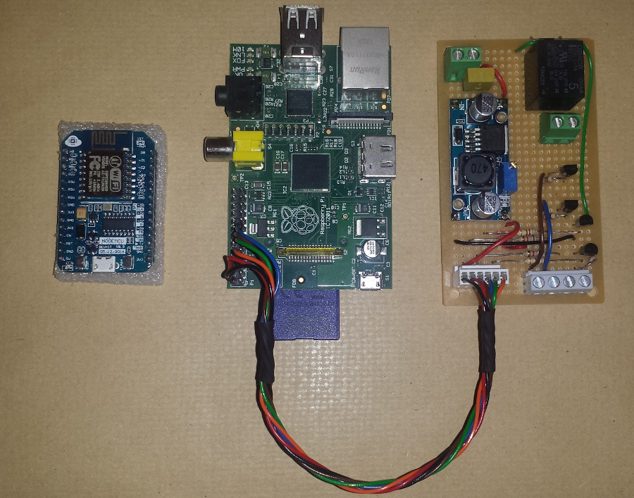
Originally I had a Python script running on the Pi which did pretty much one single job which I haven't seen mentioned here. It used the cURL tool from the Pi's command line to interface with Pushbullet's API to Push message my phone and browser (through a Chrome extension) with a message on alarm.
I have since then done some interesting upgrades:
* I have dropped the Python in favour of Node-RED (a fantastically easy to use yet powerful programming tool)
* I have the garden shed as a wireless zone on my alarm using (Wemos D1 mini in Arduino IDE using MQTT over WiFi)
Here's a Node-RED flow that shows the Pushbullet API input to the flow, an MQTT out command to a WiFi controller and some debugging/logging: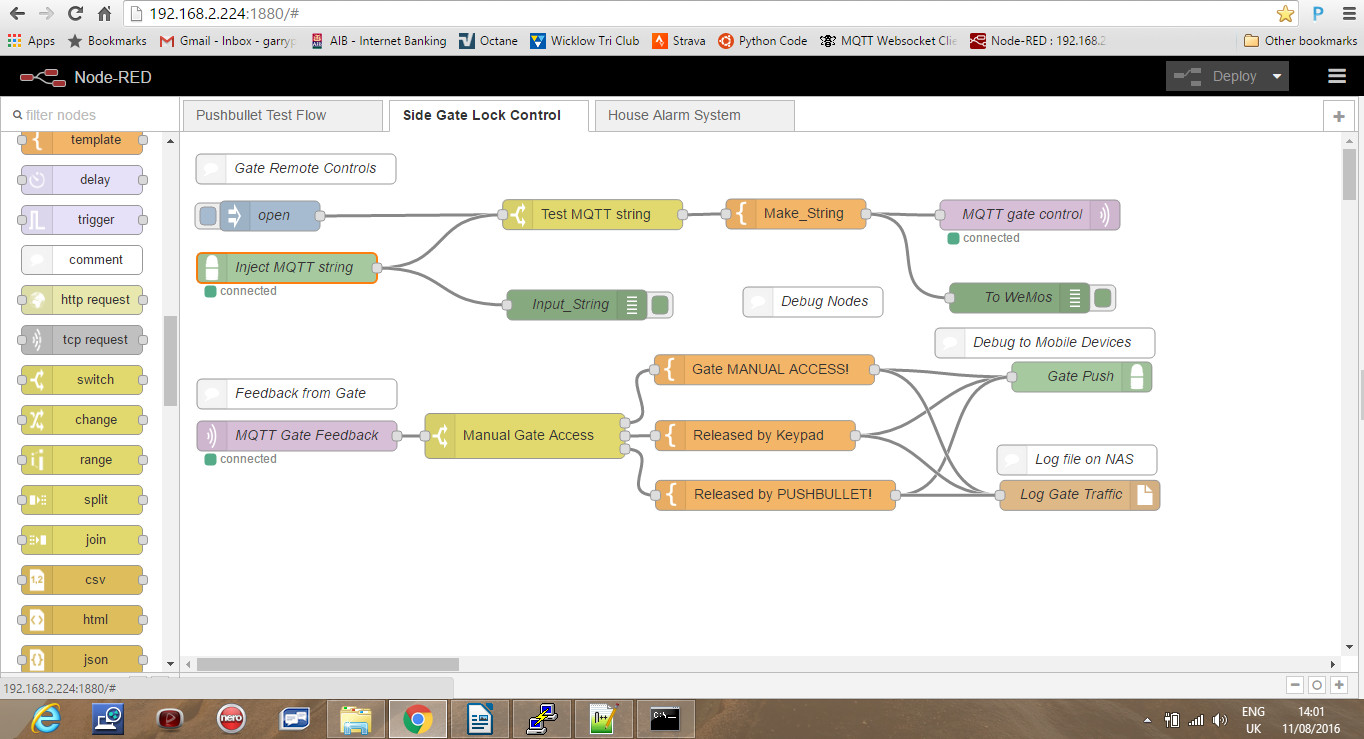
I now have a shed at the end of the garden which automatically sets/resets with the house alarm, which has a sound bomb siren of it's own and which triggers the house (fire) alarm if the shed is tampered with. The shed is solar powered with a battery which can run it for a few days with 12V led security lights and PIR sensor. The system uses a very neat user interface which is a collection of nodes in the Node-RED control flow hosted on the Pi. These are buttons, gauges and message fields which build a slick web/mobile interface. I have ported out the Node-RED through the home router firewall which allows me to monitor the whole system. I still use Pushbullet but now using Node-RED instead of cURL which is really easy and again I use a node in Node-RED to build logs on my NAS drive of pretty much everything that happens on the system; set, reset, alarm and even traffic through the side gate of the house.
This is part of what I have on my phone including analog read of the shed battery voltage and a trend: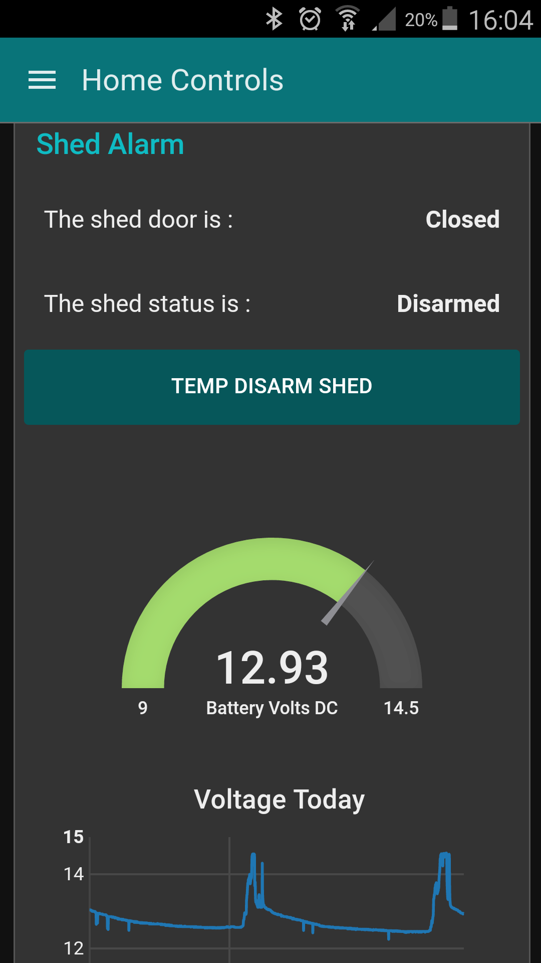
The temp disarm button allows me to lock and alarm the house then disarm the shed for 5 mins to access stuff or until the door closes for a couple of minutes at which point it resets. All of the communication over WiFi is done with MQTT which is super easy to use and has it's own background heartbeat/pinging with QOS settings and a Last Will & Testament function which allows me to log and see if any component goes offline.
Having put Node-RED on the Pi to facilitate the alarm allowed me to stick ESP8266 based boards all over the house doing all sorts of things including a full on automated spook show at halloween with zombies in coffins with rattling covers, lightning and thunder in the house and a skeleton that appeared from nowhere. Why? Because it was so easy, everything in place!
Hope that gives some inspiration
Garry0 -
Garry,
Great project! Thank you for sharing.
I'm trying to arm/disarm my Aritech CS350 using NodeMCU digital output.
Do you know how that should be wired?
Would I need to connect the digital output pin to the input of a relay, and
then wire the relay somehow to the Keyswitch input?
Thanks.
Best regards,
Niall.0 -
Hi Mrkayak.
I have no personal experience with Aritech but this diagram is poached from one of ozmo's posts.
If you look at the key switch circuit at the top of the circuit and imagine power across the two top/bottom terminals in this circuit you have the following scenarios:- The circuit is complete through the C-NC contacts of the key switch. This means a short across the top resistor and a total of 4,700 ohms through the lower one.
- The circuit is complete through the two 4K7 resistors in series (9,400 ohms in total)
- The tamper contact is open so there is no circuit present
Essentially this is a voltage divider circuit across an analogue input. I guess with the switch closed the system would disarm. Forcing a short across the top resistor gives let's say "most of" the analog input voltage to the input which the alarm can interpret as "Disarm". The current will follow the path of least resistence so will not even notice the top resistor.
Opening the circuit through the key switch would divert the path of least resistance now through the two resistors in series which will now feed only a small voltage into the input. The alarm can interpret this as a "Set" command as this would be a "Fail to safe" condition. By this I mean that tampering with the key switch circuit (cutting it) will set the alarm as distinct from disarming, not desirable.
The tamper contact will break the circuit completely so no voltage is present triggering a tamper condition and alarm activation.
I own up here: I am not an alarm technician and I have no Aritech to test so it is entirely possible that the circuit has internal pull-up or some other arrangement. So my description above while it is likely to be correct in operation it may not be electrically, don't blow up your alarm and say it was my fault, please and thanks!
If you have done some prototyping with your NodeMCU then you will know that the outputs are rated at 3.3Vdc and very low power, something like 20mA max so barely comfortable driving a bright LED. Trying to power a relay from this output will end up in a tiny smoke leak! What you need to do is find a transistor such as a 2N2222 or 2N3904, both of which I use all the time to drive relays. Both will be OK at 12V too making it easier to get a relay. These are NPN so can be put between your relay coil and ground as shown in the circuit below. You will have 12Vdc available in the panel so a standard automotive change over relay with a 12V coil would work. If you have an electrical wholesaler close they should be able to supply a relay on a base with screw terminals and using a 12V coil also, a bit easier to wire up.
You drive one of the NodeMCU pins as an output and use this and a current limiting resistor of between 500 and 1K ohms between this output and the base pin of the transistor. This will stop the transistor from over loading the NodeMCU output circuit. Look at the diagram above which I found on line. Notice that there is a diode (standard low power rectifier type such as 1N40001 is mega cheap and easy to find) across the coil of the relay. This prevents the power in the coil dissipating back through your transistor when you switch off your relay. There is a spike of back emf through the circuit which will flow through the diode and spare your transistor.
In operation your code on the NodeMCU will do as you wish to translate your remote arm/disarm request into a logic 1 or 0 on the output pin. You will have to try out your code using these circuits to work out which case causes your panel to arm or disarm, I can't help you here.
Do post an update on here to let us know how it worked. My system is stable and dependable if a little close to the wire on solar charge in my garden shed at this time of the year. It is not an ideal situation either with a tree and buildings close enough. MQTT really is a reliable and easy protocol to use to communicate with your NodeMCU and there are libraries for most of the environments ported to the ESP8266 chip. The protocol is easy to use and in a case like this a single character can be enough to control your system.
I had an alarm activation last Saturday which kicked off two push notifications and three emails and had me logged in to the CCTV cameras within 10 seconds with set, activation and reset logs all doing as they should. This has to be more dynamic than a monitor contract me thinks.
Garry0 -
Exactly - the Aritech senses the sum value of the resistors in the key zone loop - one or two resistors controls it arming or disarming - no resistors (a short - or open circuit) and the tamper alarm sounds.
So you would need source a relay module that is compatible with your nodeMCU that can switch in the above.“Roll it back”
0 -
Ozmo and Garry,
Thanks for detailed helpful responses!
I'll try connecting a real switch (as per the diagram) and see if I can arm/disarm. If that goes ok, then I can swap the switch for a relay. In this yt-vid (v=YdTvItvhb5M), the nodeMCU is driving the relay module directly (ie without need for transistor circuit).
Thanks!
Best regards,
Niall.0 -
Advertisement
-
Hi guys,
still waiting on my order for nodeMCU ...
In the meantime after a bit of research, it seems that the little
relay module
can be controlled directly by the GPIO output of the
nodeMCU. I guess using just a relay would require the transistor
circuit, but maybe the module has this built-in.
https://github.com/tribaltronik/controlboard-nodemcu-switch
I'll try it anyway, and report back.
Thanks.
Best regards,
Niall.0 -
@mrkayak:
The GPIO pins of the NodeMCU are essentially wired directly to the ESP8266 module. These GPIO pins are rated at absolute max 12mA in source circuit (supplying 3.3v to a circuit) or 20mA sink (switching 3.3v max from your circuit to ground). There is obviously some internal circuitry with pull-up resistors etc which make the output spec different for both. The circuit I showed you in the earlier post with the 2N2222 transistor is "source" where 3.3V is being applied to the base of an NPN transistor. This circuit uses a transistor to do the heavy lifting, powering the coil of your relay.
The relay modules that are sold for home automation, prototyping, arduino type circuits (all over eBay and Banggood) generally offer some isolation to protect your micro controller. By default the power used to drive the relay coil is from the NodeMCU GPIO pin but this module uses way more power than is available from the GPIO according to the spec sheet.
Moving a jumper on the relay module selects an isolated input mode with external power supply. In this case the output of your NodeMCU is used to drive an optocoupler where the maximum load applied to the NodeMCU pin is the internal LED circuit of the optocouple. It isolates the remainder of your relay control circuit from the micro controller using a light bridge but this means you have to supply the power to the driven side of the optocouple and all of the electronics on the relay module separately. If you understand how a rely works with the magnetic field moving a contact to switch off/on then imagine the optocoupler as a LED pointing at a photo transistor where the LED light is used to switch the transistor on/off, your load being connected to the transistor.
I did look at the youtube video and this guy has hooked up the relay module directly to the GPIO pin. It works, that is clear from the video. Being rated at a max current roughly in line with that taken to light the LED on the module it won't keep working for long! It is just in a different parish from it's comfort zone. The output of a NodeMCU is very unlikely to work with a 5V relay and the current to drive a 3.3v relay coil will very likely shorten the life of the ESP8266 chip considerably.
I also looked at the project on GitHub and notice that the relay module is connected to the 5V pin of the NodeMCU. You should note that this pin is the input voltage supplied to the board through the USB connection, wired directly to this pin. You can alternatively supply (max) 5V to the NodeMCU via this pin if you are not using a USB cable. This supply voltage is then regulated by the on board linear regulator to 3.3V which is the voltage that the ESP8266 module can tolerate.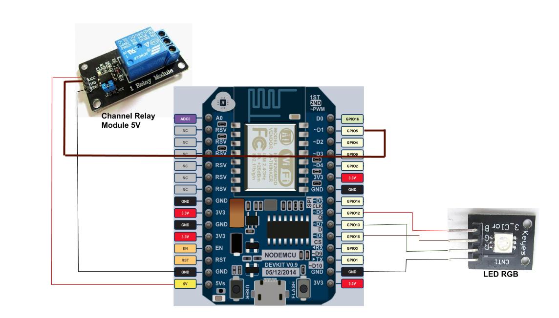
I would suggest if you have ordered your NodeMCU on line and you are used to searching and finding electronic stuff then shop for some beginner electronic assortments. You may only use 10% of the items but when you need a 1k resistor or a NPN transistor NOW, then they are worth it!
I do suggest that in terms of:- Easily locating a suitable relay to replace the keyswitch in the earlier drawing
- Interposing with the alarm panel voltage (Normally 12Vdc)
- Building a robust interface between your ESP8266 and your alarm
- Having peace of mind knowing that nothing is creaking in the red-zone...
...the circuit where the NodeMCU drives a transistor with a current limiting resistor checks all of these questions. Where on this land does mrkayak live?
Garry0 -
On the Aritech you set up the keyswitch in the menu.
Key Zone Attributes Key Zone Attributes
Fs Full set. Keyswitch fully arms system.
P1 Partguard 1. Keyswitch partially arms system using Partguard 1.
P2 Partguard 2. Keyswitch partially arms system using Partguard 2.
Us Unset. Keyswitch disarms system.
Pu Pulse. Keyswitch used must be a pulse type.
Allows arming/disarming with multiple keyswitches in a system.
Qs Quick set. Keyswitch arms panel without exit time.
Wiring wise it is a zone with 2 x 4.7k resistors
I di format the text above with spaces but its gone0 -
@mrkayak:
The GPIO pins of the NodeMCU are essentially wired directly to the ESP8266 module. These GPIO pins are rated at absolute max 12mA in source circuit (supplying 3.3v to a circuit) or 20mA sink (switching 3.3v max from your circuit to ground). There is obviously some internal circuitry with pull-up resistors etc which make the output spec different for both. The circuit I showed you in the earlier post with the 2N2222 transistor is "source" where 3.3V is being applied to the base of an NPN transistor. This circuit uses a transistor to do the heavy lifting, powering the coil of your relay.
The relay modules that are sold for home automation, prototyping, arduino type circuits (all over eBay and Banggood) generally offer some isolation to protect your micro controller. By default the power used to drive the relay coil is from the NodeMCU GPIO pin but this module uses way more power than is available from the GPIO according to the spec sheet.
Moving a jumper on the relay module selects an isolated input mode with external power supply. In this case the output of your NodeMCU is used to drive an optocoupler where the maximum load applied to the NodeMCU pin is the internal LED circuit of the optocouple. It isolates the remainder of your relay control circuit from the micro controller using a light bridge but this means you have to supply the power to the driven side of the optocouple and all of the electronics on the relay module separately. If you understand how a rely works with the magnetic field moving a contact to switch off/on then imagine the optocoupler as a LED pointing at a photo transistor where the LED light is used to switch the transistor on/off, your load being connected to the transistor.
I did look at the youtube video and this guy has hooked up the relay module directly to the GPIO pin. It works, that is clear from the video. Being rated at a max current roughly in line with that taken to light the LED on the module it won't keep working for long! It is just in a different parish from it's comfort zone. The output of a NodeMCU is very unlikely to work with a 5V relay and the current to drive a 3.3v relay coil will very likely shorten the life of the ESP8266 chip considerably.
I also looked at the project on GitHub and notice that the relay module is connected to the 5V pin of the NodeMCU. You should note that this pin is the input voltage supplied to the board through the USB connection, wired directly to this pin. You can alternatively supply (max) 5V to the NodeMCU via this pin if you are not using a USB cable. This supply voltage is then regulated by the on board linear regulator to 3.3V which is the voltage that the ESP8266 module can tolerate.
I would suggest if you have ordered your NodeMCU on line and you are used to searching and finding electronic stuff then shop for some beginner electronic assortments. You may only use 10% of the items but when you need a 1k resistor or a NPN transistor NOW, then they are worth it!
I do suggest that in terms of:- Easily locating a suitable relay to replace the keyswitch in the earlier drawing
- Interposing with the alarm panel voltage (Normally 12Vdc)
- Building a robust interface between your ESP8266 and your alarm
- Having peace of mind knowing that nothing is creaking in the red-zone...
...the circuit where the NodeMCU drives a transistor with a current limiting resistor checks all of these questions. Where on this land does mrkayak live?
Garry
Hi Garry,
Thanks for all your help with this. It took ages to get nodeMCU, etc. So long that I ended up doing another project to control an
extractor fan in the bathroom based on humidity readings from a DHT22 sensor. Everything was working fine .. but as you
so helpfully pointed out the nodeMCU doesn't have enough power to switch the relay properly. It can turn the relay on and off,
but not while it's WiFi connected .. and reading DHT sensor at the same time
So now I will work on the transistor circuit to control the relay. My plan is to work on the alarm project as soon as I'm
finished this one.
Thanks again.
Best regards,
Niall.0 -
-
conor o brien wrote: »Hi Ozmo, Just came across this thread, Looks like you done some great work,
Could i also get a look at your HKC docs.
Thanks
Thanks - Sure - Ill send on:
Some updates:
Fixed: There was an issue reported with the blinking keypad lights HKC can optionally do at Part-set being misinterpreted as an alarm - this is fixed in the latest code.“Roll it back”
0 -
Oh - and most the parts can be bought on Adverts.ie so you dont have to wait weeks to arrive from China - eg. here is the power supply module for 3 euros:
http://www.adverts.ie/other-electronics/lm2596s-dc-dc-adjustable-step-down-power-supply-module/9024399“Roll it back”
0 -
Thanks for this, my goal is to try and apply what you have done to esp8266 based module and a HKC 1070.
Great to know about the stuff on adverts as well.
Thanks again.:)0 -
Pics of my HKC alarm interface which I thought about implementing for nearly a year. The design changed a few times in my head and I have eventually arrived at this design. I was going to add a GSM dialler e.g. SIM900A/SIM800L but I have abandoned that for now. Working very well for nearly a month now.
Electronics used:
Wemos D1 mini ESP8266 €2.18 on aliexpress
DC-DC convertor €0.60
Quad optoisolator (PC847 or four PC817) €0.40
2k resistors (<€0.05)
Miscellaneous connectors, wire, board <€2
Features:
1. Publishes change in output status to MQTT. GPIO inputs are debounced at 50ms.
2. Publishes to MQTT at various intervals; RSSI signal strength, status of all panel outputs, clientid on boot (from mac address)
3. Interfaces to Node-red server to send emails via gmail node and SMS txts via Twilio node on change in panel outputs or alarm activations.
4. Reconnects on loss of wifi or link to MQTT server.
5. Allows OTA updates for easy development changes from the desk.
Anybody interested in the arduino code can pm me.0 -
Looks good!
This is very similar to what I have done in our home alarm where I too use MQTT and Node-RED. You must have a MQTT server or service set up so there are more options open to you.
Remote set/reset and monitor of other buildings such as garage/shed.
This was the second reason I upgraded mine along side monitoring and notification. If you are using GPIO's from the panel to know when the system is set or not then an other D1Mini in your garage or shed also talking to your Node-RED flow via MQTT and you can secure this also. I found that my alarm panel had an input circuit for a fire alarm system but the installer had bridged across the input with a staple. I was able to put an opto-isolated relay on my Raspberry Pi GPIO (I have one of these in the panel interfaced (both input/output) with the panel's GPIO) which is where my MQTT broker and NodeRed are running.
I publish the alarm panel status on MQTT when it sets/resets so the other D1 Minis I have then enable/disable the reed switches and PIR sensors on their GPIO. They then publish if there is an "intrusion" and the house alarm is triggered via the fire alarm circuit.
I have recently modified a regular €10 smoke alarm which is in my attic space to include a mini DC-DC buck converter with an enable pin which when enabled by the smoke alarm boots up an ESP01 module. This connects via MQTT to also trip the fire alarm circuit and send me a push message via Pushbullet.
FYI there is a Pushbullet node in Node-RED which will instantly push a notification to your phone and if enabled an extension of Google Chrome browser. Let me know if you would like parts links, schematics or code for any of these accessories?
Garry0 -
Advertisement


Advertisement