Advertisement
If you have a new account but are having problems posting or verifying your account, please email us on hello@boards.ie for help. Thanks :)
Hello all! Please ensure that you are posting a new thread or question in the appropriate forum. The Feedback forum is overwhelmed with questions that are having to be moved elsewhere. If you need help to verify your account contact hello@boards.ie

Shed build - help

Options
2456711

Comments

  • Registered Users Posts: 1,614 ✭✭✭victor8600


    For a 15 sq.m shed, I think that more windows are needed. A single window on the narrow wall will not illuminate the 4.8 m length of the shed much.


  • Registered Users Posts: 31,014 ✭✭✭✭Lumen


    listermint wrote: »
    I would say wood fibre has terrible heat conductivity so it would be a terrible idea. The heat would be slow to release but equally slower to store.

    Isn't that the idea behind "decrement delay"? That you even out temperature fluctuations over the day/night cycle?


  • Registered Users Posts: 31,014 ✭✭✭✭Lumen


    victor8600 wrote: »
    For a 15 sq.m shed, I think that more windows are needed. A single window on the narrow wall will not illuminate the 4.8 m length of the shed much.

    You're right, plus it's in a heavily shaded area. I haven't figured out the side glazing yet, maybe full height fixed glazing between a few studs, and then leave the single front window as an opener. Solar gain isn't an issue due to heavy shading.

    I think triple glazing is 30kg/sqm, so each stud window would be 30kg.


  • Registered Users Posts: 31,014 ✭✭✭✭Lumen


    Ground screws.

    Whilst the spacing is near-perfect (<5mm diff in diagonals and plate heights) the vertical alignment is off a bit on some of them. This was expected. The installer said this is the hardest ground they've ever come across, and the screws can get deflected a bit during insertion.

    So I'll need some steel packers to level before attaching the "ring beam" with coach screws.

    OZi6_S54.jpg

    0_Ex0_Zb_W.jpg


  • Registered Users Posts: 31,014 ✭✭✭✭Lumen


    Lumen wrote: »
    So I'll need some steel packers to level....
    Or maybe some epoxy bearing mortar?

    http://www.arconsupplies.co.uk/epoxy-bearing-mortar

    Where would I get such a thing in Ireland?

    edit: maybe here https://sitetech.ie/product-item/epoxy-mortar/

    Class R4 is ≥ 45MPa compressive strength, which is eh, sufficient.


  • Advertisement
  • Closed Accounts Posts: 9,764 ✭✭✭my3cents


    Are there any really really expensive alternatives to a bit of wood cut to size and drilled that you haven't explored yet?


  • Registered Users Posts: 31,014 ✭✭✭✭Lumen


    my3cents wrote: »
    Are there any really really expensive alternatives to a bit of wood cut to size and drilled that you haven't explored yet?
    :D

    I don't like woodwork. Which could shortly pose a problem in this project.


  • Closed Accounts Posts: 9,764 ✭✭✭my3cents


    I really don't think I'd be that happy with the way those ground anchors have gone in? I don't think they would have cut the mustard on Building Alaska?

    One option might be to get some short lengths of U shaped iron section bolt them to the top of the anchors and then get your level inside the U sections and bolt from the sides?


  • Registered Users Posts: 31,014 ✭✭✭✭Lumen


    my3cents wrote: »
    I really don't think I'd be that happy with the way those ground anchors have gone in? I don't think they would have cut the mustard on Building Alaska?
    It is mildly annoying but I'm not sure it's possible to resolve since deflection of the screws during insertion is inevitable.

    The ground almost broke the enormous drill they used:

    https://www.schraubfundamente.de/en/eindrehmaschinen/kr_e_20_ground_screw_driver_z1/

    ...which has 4500 Nm of torque. Even the ones which are furthest out of the ground (by 400mm) have a good 850mm below ground level.

    When fully inserted, the rating of the 1300 screws is:

    Compression: 25.00 kN
    Tension: 12.50 kN
    Horizontal: 5.50 kN.

    Since they're not fully inserted, maybe the better values to use are those for the 800 long screws:

    Compression: 13.50 kN
    Tension: 7 kN
    Horizontal: 3.50 kN.

    Since the lack of levelling of the bearing surface can be fixed by shimming or whatever, I guess one question is whether the slightly off-axis orientation of a couple of screws taxes the horizontal load bearing capacity of the screws. Probably not, since it's only a couple of degrees.

    But it's conceivable that I end up with 10kN through one of the screws, which doesn't leave that much margin against the 13.5kN compression load limit, although the pre-dimensioning tables state "geotechnical standard DIN 1054, Nov. 1976 global safety factor approx. 2.0".

    That said "the stated load bearing capacity values were determined in soil of type: loam, semisolid (TL,TM)." and I have clay, which in theory has lower load bearing capacity, but in practice (given the difficulty of driving in the screws) seems decent enough.

    Hmmm.


  • Registered Users Posts: 1,576 ✭✭✭Glass fused light


    Lumen wrote: »
    You're right, plus it's in a heavily shaded area. I haven't figured out the side glazing yet, maybe full height fixed glazing between a few studs, and then leave the single front window as an opener. Solar gain isn't an issue due to heavy shading.

    I think triple glazing is 30kg/sqm, so each stud window would be 30kg.

    With heavy shading you also need to factor in the difference in summer with dappled light comming through the moving leaves and the full winter sun through bare branches. Small panels in each stud at the under the eves would give you more consistent light than a long single panel or two.
    Similar if you are working in it a row of glass at desk hight would give you better light into the summer when the sun is higher in the sky.
    https://www.pilkington.com/resources/pilkingtonsunanglecalculatormanual.pdf


  • Advertisement
  • Registered Users Posts: 443 ✭✭Zebbedee


    Lumen wrote: »
    Ground screws.

    Whilst the spacing is near-perfect (<5mm diff in diagonals and plate heights) the vertical alignment is off a bit on some of them. This was expected. The installer said this is the hardest ground they've ever come across, and the screws can get deflected a bit during insertion.


    They must have hit rocks under the surface.


  • Registered Users Posts: 31,014 ✭✭✭✭Lumen


    Zebbedee wrote: »
    They must have hit rocks under the surface.
    Yep, and/or roots.

    The photos are a bit deceptive. Whilst some of the screws aren't totally vertical (worst case is a plate 8% off horizontal plane), the heights are OK.

    I did some measuring today and it looks like they'll all be able to sit under the ring beam (see below).

    Have tried to take my3cents advice on board and avoid epoxy mortar in favour of wood solutions, I think instead I might try routing the bottom of the beam so that it sits over the screws (ok, I haven't entirely taken the "keep it simple" spirit of the advice).

    The reason they are all oriented differently is that we prioritized height alignment over rotational alignment. Every quarter turn changes the height by something like 10mm (can't remember exactly).

    Screen_Shot_2018-08-04_at_14.14.08.png


  • Closed Accounts Posts: 9,764 ✭✭✭my3cents


    Lumen wrote: »
    ...

    The reason they are all oriented differently is that we prioritized height alignment over rotational alignment. Every quarter turn changes the height by something like 10mm (can't remember exactly).
    ...

    That does seem to be a bit of a design flaw. Very surprised they don't have their own fittings for making up for that 10mm and allowing for 5-10mm of misalignment.


  • Registered Users Posts: 31,014 ✭✭✭✭Lumen


    my3cents wrote: »
    That does seem to be a bit of a design flaw. Very surprised they don't have their own fittings for making up for that 10mm and allowing for 5-10mm of misalignment.

    They do have such fittings. Ze Germans have solved the problem. For the variants which are designed to hold up poles, there is an eccentric fitting. For variants which are designed to support building-type things, there are post mounts with threaded things to raise and lower. But that adds another 150mm or so, which I don't want to give up..

    My design is supposed to overcome the expected variation in horizontal plane by having a massive bearing surface. What wasn't really expected was the off-axis on the vertical. So I just need to shim it, if I am prepared to lose another cm or so. Or if not, use a router to recess the metal plate.

    edit: I have to deal with the fact that the coach screw heads won't bear flat on the underside of the plates, so today I ordered some "conical seat washers" along with the 150mm coach screws (both A4 stainless) to compensate.


  • Registered Users Posts: 443 ✭✭Zebbedee


    Lumen wrote: »

    edit: I have to deal with the fact that the coach screw heads won't bear flat on the underside of the plates, so today I ordered some "conical seat washers" along with the 150mm coach screws (both A4 stainless) to compensate.


    You could use countersunk screws here.


  • Registered Users Posts: 31,014 ✭✭✭✭Lumen


    I got wood! :D

    Douglas Fir to be precise. From Germany, via Wicklow.

    300mm x 75mm (x2 or x3) for the beams, 150mm x 75mm (x2) for the end posts. C24 graded.

    Let the fettling commence...

    Big pics here: https://imgur.com/a/eBw3iKq

    zbfhkq0m.jpgQs0QyxDm.jpgXDkXGppm.jpg


  • Registered Users Posts: 443 ✭✭Zebbedee


    Douglas is great for beams/rafters.
    I got mine for a cedar clad shed I built from the guys
    just before Kellys yard in Glenealy.
    They were from locally sourced Douglas.
    Not sure about any classification though.


  • Closed Accounts Posts: 9,764 ✭✭✭my3cents


    Nice looking timber apart from the start of decay in the shorter wide piece. I'd give that a good soaking in preservative just it case. It won't get any worse if it stays dry but looks like it was allowed to get wet when stacked.


  • Registered Users Posts: 31,014 ✭✭✭✭Lumen


    my3cents wrote: »
    Nice looking timber apart from the start of decay in the shorter wide piece. I'd give that a good soaking in preservative just it case. It won't get any worse if it stays dry but looks like it was allowed to get wet when stacked.

    Is that the black stuff? Should I plane it off?

    The shorter sections have by far the least load as they're only covering about a third of the span of the long sections and have no roof load, but I don't want any rot spreading.

    I picked up some ProTim today. Not sure whether I should plane first or just lash it on.


  • Closed Accounts Posts: 9,764 ✭✭✭my3cents


    Lumen wrote: »
    Is that the black stuff? Should I plane it off?

    The shorter sections have by far the least load as they're only covering about a third of the span of the long sections and have no roof load, but I don't want any rot spreading.

    I picked up some ProTim today. Not sure whether I should plane first or just lash it on.

    Just lash the protim on it. I've had it in a lot of construction timber that I have had stored thats got wet provided it doesn't get any worse protim will stop it in its tracks but you'll always have the dark stain. If the timber stays dry it doesn't get worse anyway.


  • Advertisement
  • Registered Users Posts: 31,014 ✭✭✭✭Lumen


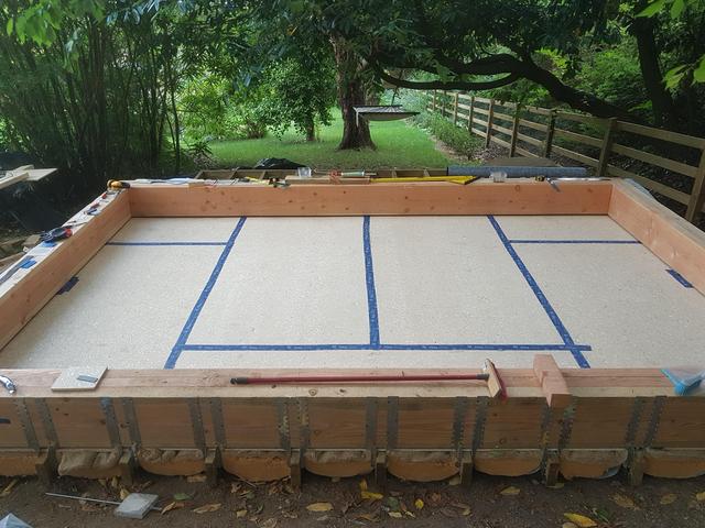
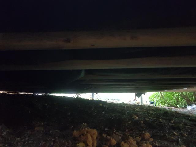
    Some progress this weekend.

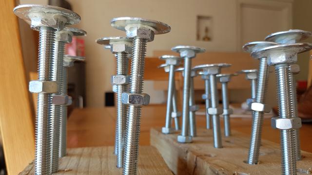
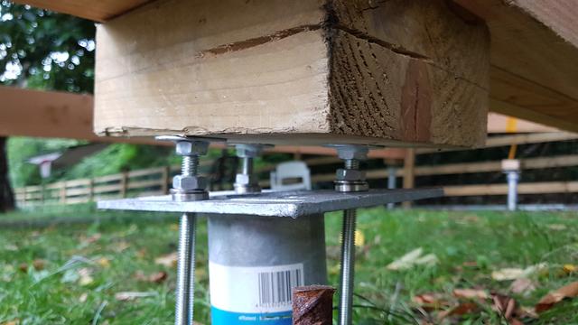
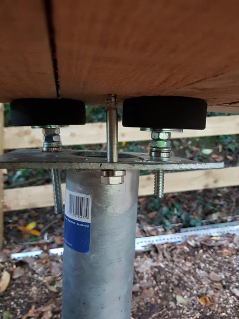
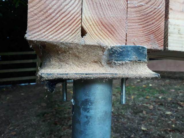
    Made some levelling bolts from M10 threaded rod, penny washers, nuts and epoxy, and used the conical washers to mate the bottom nut with the ground screw plate. Those conical washers are sexy.

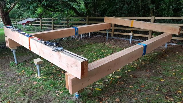
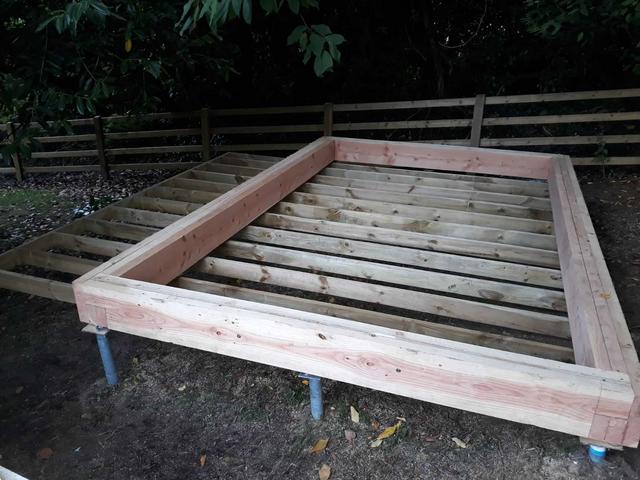
    Laid out the frame, levelled and squared. Will wait for my track saw to arrive before cutting.

    I think I'll build the frame up with the levelling bit open, and then epoxy grout when the coach screws are in. That'll allow me to fine-tune the levels.

    Those 3" blocks are only temporary until the frame is made. I'll either rest the frame on the washer-bolt tops or get some plate alu and drill it for the coach screws.

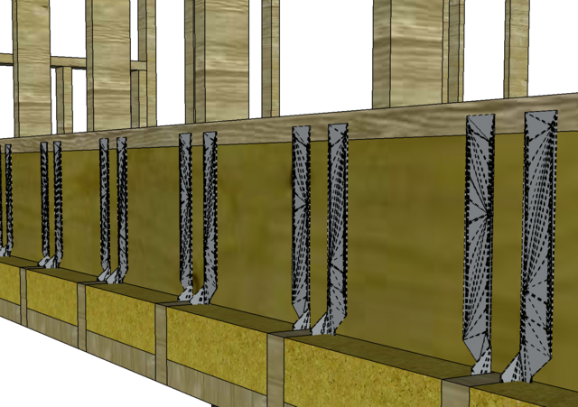
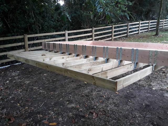
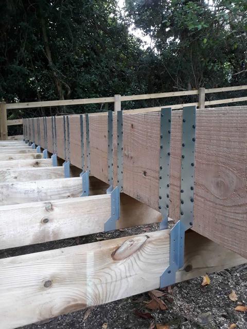
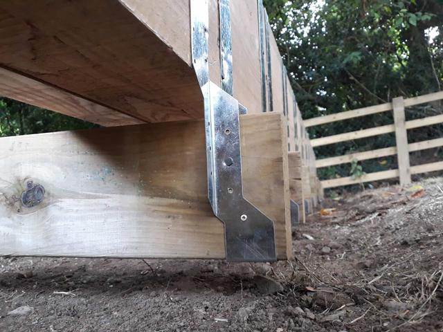
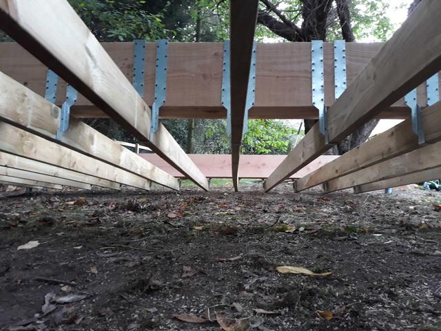
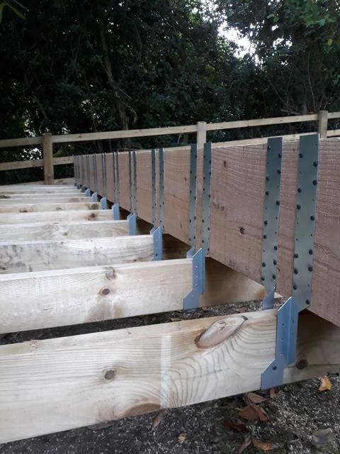
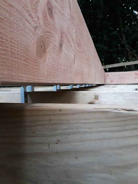
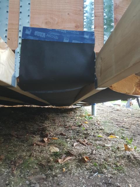
    I plan to sling the floor joists under the frame on long leg jiffy hangers attached on the outside of the frame. This will reclaim the headroom I've lost by the height of the screws and spacers, leave the interior face of the frame beams clean of metalwork, and act as a shelf for the external insulation. Should have a couple of cm clearance above ground, but since the insulation and cladding will overhang there won't be any rain splash to contend with.

    My current favourite tool: alloy bar clamp/spreader

    https://www.axminster.co.uk/axminster-trade-clamps-alloy-bar-clamp-spreader-ax945573

    Not only will it do 180kg of clamping force (which has kept me alive today) but it will also spread with the same force so can be used as a jack to lift the beams off the ground screws for repositioning. Lovely thing! Can never have enough clamps...

    Anyway, it's a beast. About 500kg so far! I'm going to stick the door on the left hand side to enable more steps up to the door. And because the floor will be sunk 300mm inside the frame, there will be more steps down on the inside. More drama! Or trip hazards, whatever. :D

    Bigger pics: https://imgur.com/a/1ayRGDS

    Wpdj_OZA.jpg6_KWH3w_B.jpgIKcn_Lmz.jpgLLrhe02.pngMSy_Twf_Z.jpgUVIv_Bj_H.jpg


  • Registered Users Posts: 31,014 ✭✭✭✭Lumen


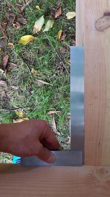
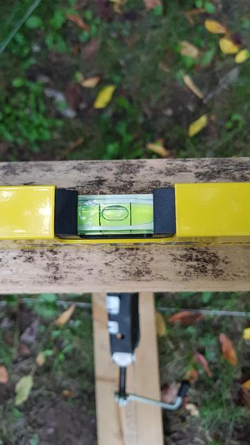
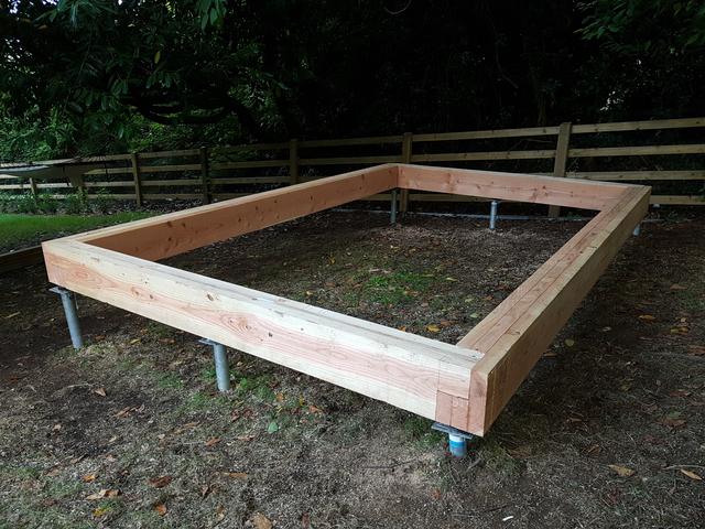
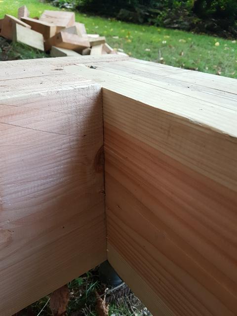
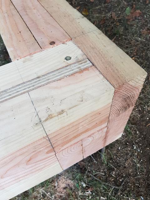
    OK, this last bit has been quite fiddly. I think at least three days to measure, cut, glue, screw and bolt down the frame. Maybe four. God it was hard.

    Rough Steps:

    - Level and square the uncut timber on the ground screws using the epoxied levelling bolts.
    - Nearly break my wife's feet when the whole thing collapses (no actual injuries were incurred). Have a stern word with myself.
    - Redesign the levelling screws with solid vulcanized rubber ice hockey pucks.
    - Re-level and square the uncut timber.
    - Cut the short beams, glu-laminate with Cascamite and screw with a combination of hex-headed self-drilling Timco screws and coach screws.
    - Re-square and re-level again.
    - Repeat the gluing and screwing with the long beams, except using plate-headed Timco screws rather than coach screws (don't have the right length coach screws yet)
    - Strap everything tight with heavy duty ratchet straps.
    - Re-square and re-level again.
    - Screw the corners with more Timco hex-headed screws, skewed to avoid screwing into end grain.
    - Drill up into the beams with 8mm auger bit using right-angle drill adapter on the low side, one coach screw per ground screw with conical washer.

    The result is pleasingly solid. Diagonals are within 4mm of square. Whole thing is bubble-level well within the margins.

    Next step, suspended floor....

    Large pics: https://imgur.com/a/agSKEF7

    ZTu4_Hsv.jpgvlyeojf.jpgcx_Ah_Ct_A.jpgGkr_Jw3p.jpg


  • Registered Users Posts: 7,855 ✭✭✭Rows Grower


    My new favourite thread.

    That is gonna be some shed, fair play.

    "Very soon we are going to Mars. You wouldn't have been going to Mars if my opponent won, that I can tell you. You wouldn't even be thinking about it."

    Donald Trump, March 13th 2018.


  • Registered Users Posts: 3,121 ✭✭✭Dr_Colossus


    Nice project and fair play for undertaking it and posting all the details and pics. Going to be serious weight on those epoxied leveling bolts and rubber ice hockey pucks, are they going to be able for the strain as look fairly light (10mm?). Any concerns with the rubber in the ice hockey pucks degrading over the years.

    I realise the ground stays are at slightly different heights and angles but seems a shame to be reducing all that surface area down to a couple of washers which in turn concentrates all the weight onto two points of the flange rather than a more evenly distributed load including the pipe itself. Would chiseling some of the underside of the frame be an option to have it all sitting directly on the ground stays? Would involve a lot of lifting and additional time but that would be my take having no experience in the matter or researching how such a raised platform is normally secured.


  • Registered Users Posts: 31,014 ✭✭✭✭Lumen


    Nice project and fair play for undertaking it and posting all the details and pics. Going to be serious weight on those epoxied leveling bolts and rubber ice hockey pucks, are they going to be able for the strain as look fairly light (10mm?). Any concerns with the rubber in the ice hockey pucks degrading over the years.

    I realise the ground stays are at slightly different heights and angles but seems a shame to be reducing all that surface area down to a couple of washers which in turn concentrates all the weight onto two points of the flange rather than a more evenly distributed load including the pipe itself. Would chiseling some of the underside of the frame be an option to have it all sitting directly on the ground stays? Would involve a lot of lifting and additional time but that would be my take having no experience in the matter or researching how such a raised platform is normally secured.

    Yeah, I've thought a bit about this. The pucks aren't doing anything except gripping the timber since they've a threaded rod up the middle, with a nut slightly recessed on the top. So the structure is effectively resting on 18 M10 bolts (or 12 M10 threaded rods and 6 M10 coach screws), plus the washers.

    In fact the coach screws aren't holding it up as I ran out of washers, but the plan is to add them back in. I could get penny washers for more cross section, although I'd still have the smaller conical washers as the weakest link so maybe not worth the expense.

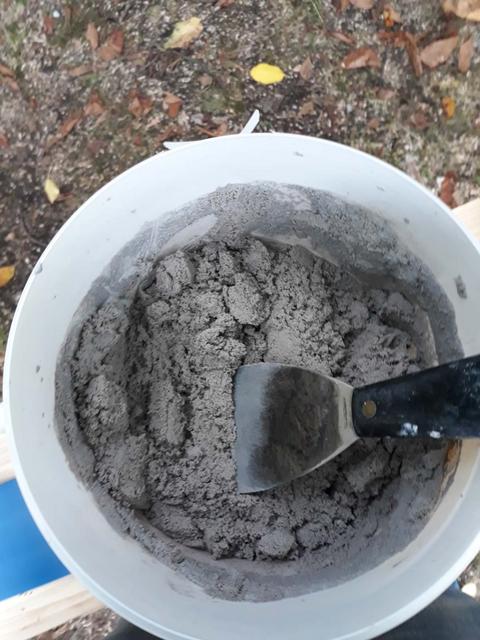
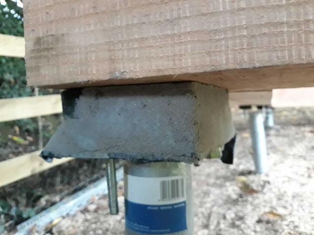
    I reckon the best job is to just fill the gap with epoxy grout later in the build, but I don't want to do that until I'm absolutely happy with it all. Plus I'd need maybe 2 buckets of grout and I only have one. But for 40 euro or whatever that's a poor excuse.

    Anyway, if I do nothing but add some washers they'll be say 5000kg sitting on about 5000mm2 of steel (each M10+washer stack is about 300mm2), so that's 10N/mm2. Compressive strength of steel is well in excess of 100N/mm2.

    I'd imagine the ground screws will move or some weak link in the chain will shear before the steel fails in compression.

    edit: or I could just add more steel rod/washer stacks, as I have loads of holes free in the ground screw plates.


  • Closed Accounts Posts: 9,764 ✭✭✭my3cents


    I was going to suggest filling with epoxy if you are that worried about it.

    You could also put in a wooden wedge from each side where there's a gap and tap away until the won't come out.


  • Closed Accounts Posts: 18,268 ✭✭✭✭uck51js9zml2yt


    How much did the groundscrews cost you?

    Its giving me an idea for a poly tunnel!


  • Registered Users Posts: 443 ✭✭Zebbedee


    my3cents wrote: »

    You could also put in a wooden wedge from each side where there's a gap and tap away until the won't come out.


    +1 on this.
    I'd prefer this method rather than epoxy.


  • Registered Users Posts: 31,014 ✭✭✭✭Lumen


    How much did the groundscrews cost you?

    Its giving me an idea for a poly tunnel!

    €882.84 including installation.

    Price list and pre-dimensioning tables attached. Krinner brochure with all the part descriptions is on various sites easily found via Google (massive doc so can't attach).


  • Advertisement
  • Registered Users Posts: 31,014 ✭✭✭✭Lumen


    Zebbedee wrote: »
    +1 on this.
    I'd prefer this method rather than epoxy.

    I don't see how it's better than this, which is what I bought before I went with the rods and pucks approach:
    https://www.goodwins.ie/products/Everbuild-Epoxyset-106-Rapid-Cure-5Kg.html

    EPOXYSET 106 RAPID CURE
    TECHNICAL INFORMATION
    Compressive Strength >90N/mm2 (EN12190)
    Tensile Adhesion Strength >3N/mm2 (EN1542)

    That gives compressive strength over the six 140x189mm ground screw plates of 14 million newtons.

Advertisement