Advertisement
If you have a new account but are having problems posting or verifying your account, please email us on hello@boards.ie for help. Thanks :)
Hello all! Please ensure that you are posting a new thread or question in the appropriate forum. The Feedback forum is overwhelmed with questions that are having to be moved elsewhere. If you need help to verify your account contact hello@boards.ie
Hi all! We have been experiencing an issue on site where threads have been missing the latest postings. The platform host Vanilla are working on this issue. A workaround that has been used by some is to navigate back from 1 to 10+ pages to re-sync the thread and this will then show the latest posts. Thanks, Mike.
Hi there,
There is an issue with role permissions that is being worked on at the moment.
If you are having trouble with access or permissions on regional forums please post here to get access: https://www.boards.ie/discussion/2058365403/you-do-not-have-permission-for-that#latest

Aritech Alarm Internet Dialler

123468

Comments

  • Registered Users, Registered Users 2 Posts: 3,876 ✭✭✭ozmo


    Hans1960 wrote: »
    Hi, the following error message appear when uploading to my Arduino Uno.

    Not sure - but the error is suggesting you might have entered 256 as the network mask in the config? The usual value is 255.255.255.0 ?
    Try compile a fresh copy from github?


    Re: CD91 - I have tested the CD91 here- and it did work - but I do remember the timing was very tight because that Alarm panel can have so many keypads to communicate with and so to keep things responsive the panel doesn't wait as long for a response as the other Aritech panels.
    Can you try this version of the code with slightly different timing?-> here

    “Roll it back”


  • Closed Accounts Posts: 10 Hans1960


    Hi Ozmo,
    Thanks for your suggestions, i will check the network mask and download the new code this week and keep you informed about the result.


  • Closed Accounts Posts: 10 Hans1960


    Hi Ozmo,
    Well, first of all, where do i set the netmask in the config, i did not find anything.
    Secondly, i downloaded the version refering to your link but had no result, even worse..
    The arduino does not send emails and i cannot connect to the RKP webpage.
    Also the CD91 does not find the Arduino RKP.
    See below error message when uploading to the Arduino Uno.


    In file included from C:\Program Files (x86)\Arduino\libraries\Ethernet\src\Dns.cpp:8:0:

    C:\Program Files (x86)\Arduino\libraries\Ethernet\src\Dns.cpp: In member function 'uint16_t DNSClient::BuildRequest(const char*)':

    C:\Program Files (x86)\Arduino\libraries\Ethernet\src&#0;ty/w5100.h:457:25: warning: result of '(256 << 8)' requires 18 bits to represent, but 'int' only has 16 bits [-Wshift-overflow=]

    #define htons(x) ( (((x)<<8)&0xFF00) | (((x)>>8)&0xFF) )

    ~~~^~~

    C:\Program Files (x86)\Arduino\libraries\Ethernet\src\Dns.cpp:164:18: note: in expansion of macro 'htons'

    twoByteBuffer = htons(QUERY_FLAG | OPCODE_STANDARD_QUERY | RECURSION_DESIRED_FLAG);

    ^~~~~

    Sketch uses 20690 bytes (64%) of program storage space. Maximum is 32256 bytes.
    Global variables use 1043 bytes (50%) of dynamic memory, leaving 1005 bytes for local variables. Maximum is 2048 bytes.


  • Closed Accounts Posts: 10 Hans1960


    Hi Ozmo, do you have any additional suggestion for me to solve this issue ?


  • Registered Users Posts: 18 darkonethree


    Hans1960 wrote: »
    Hi Ozmo,
    Well, first of all, where do i set the netmask in the config, i did not find anything.


    in WebSocket.cpp it looks like you can set the subnet & gateway here.
    you can see 254 has been set here with the other ip address numbers coming from IP_A, B & C which were set in config.h.

    IPAddress ip( IP_A, IP_B, IP_C, IP_D);	    //Give the device a unique IP
    IPAddress gateway( IP_A, IP_B, IP_C, 254 );   //Gateway (your Router)
    IPAddress subnet( 255, 255, 255, 0 );	            //typically dont need change
    

    I'm having difficulty in getting emails to work myself, setup a gmx account, used an old eircom account both with no joy. I'll keep trying...


  • Registered Users Posts: 18 darkonethree


    Hi all, ozmo,

    Sorry for the question but I have uploaded your CastleHKCArduinoRKP code to the Arduino Uno and Ethernet Shield. I do not have the HKC panel or the circuit built just yet.

    I can see the web interface on port 8383 so thats working! :)

    However I'm trying to test if the e-mail is working and according to your code it should send out an

    SMTP::Init();
    SMTP::QueueEmail(START);

    which should send an e-mail to say that the The House Alarm has just started

    But i'm not getting any e-mail?

    In fact when I load up WireShark and monitor traffic, I can see ping requests and web traffic on 8383 when i load the web page or ping the Arduino. But if I don't see any traffic at all to suggest an e-mail is being sent or attempted.

    Am I missing something? Everything in your config.h and other files otherwise looks correct.


  • Registered Users Posts: 18 darkonethree


    Update:

    Ah, I can see that Chrome doesn't work with the sockets perhaps, tried "Pale Moon" browser and I'm getting a Not Connected??? message which is better. Also capturing this on WireShark shows it's trying to send data each time you press a number key on the web page. This is more than was working with Chrome so don't use Chrome....

    Still cant get e-mails to work. It's like it's not even trying to send an email or getting that far in the code. I dont know....

    I'm beginning to wonder with Chrome not working are other things just not working with the Arduino libraries as the code is a good few years old now.

    I wish I had a way to debug this.


  • Registered Users, Registered Users 2 Posts: 3,876 ✭✭✭ozmo


    It works for me with Chrome and Safari on an IPhone still - that's the way I've always used it.

    You cannot use gmail and many smtp servers anymore as more and more require a type of encryption that will not fit in the arduino - you could set up your own smtp server using an rpi?

    How the email works: The code has to reply to the panel really quickly (within a few milliseconds) so there is no time to send an email - instead it flags that it needs to send one.
    An email is queued at power up (SMTP::QueueEmail(START);) and if an alarm happens -
    If one is queued - the email is actually sent from the main loop SMTP::SendEmailProcess() - there are several steps to sending an email - log in etc - this sees what step is needed next to get the email sent and does that.

    I wish I had a way to debug this.

    If you have an arduino with two serial ports (eg. Leonardo) you can print messages back to the pc while its running.

    But best way is to download the trial version of Visual Studio Micro (link) - it will allow you to step through, place breakpoints in the code and examine variables etc. Its really good.

    “Roll it back”


  • Registered Users Posts: 18 darkonethree


    Hi Ozmo,

    Thanks for reply!

    Perfect, so you need to have it connected to the Alarm Panel before it will send the email, is there any way around this? a flag I could use?

    I am just waiting on a few cables & connectors for the Arduino before I can wire it into the panel so was hoping to test as much as i could before hand.


    on a seperate note:
    Have you used Home Assistant before? I have wired in some of the PIR's and Door sensors already into a raspberry pi and am sending any change events to Home Assistant over MQTT. In addition then monitoring the alarm panel using your Arduino over ethernet is the icing on the cake. home-assistant.io along with some PC817 4 channel boards on ebay can interface directly from 12V to 3.3v


  • Registered Users Posts: 18 darkonethree


    home assistant attached snapshot showing alarm panels PIR's and Door sensor history & current state...

    The window titled "Arduino" is an iFrame of your Arduino script. Which i hoped would have shown the keypad but for some reason it's blank. I think this has something to do with you using websockets?


  • Advertisement
  • Registered Users, Registered Users 2 Posts: 3,876 ✭✭✭ozmo


    Press F12 to enter debug mode in Chrome- look at the console tab for any errors- and look for any red lines in the network tab.

    https://javascript.info/debugging-chrome

    “Roll it back”


  • Registered Users Posts: 18 darkonethree


    looks like the latest chrome on Android/PC doesn't like websockets?


  • Moderators Posts: 6,870 ✭✭✭Spocker


    I had trouble too running this in Chrome - @darkonethree try Firefox instead, it worked a treat for me


  • Registered Users Posts: 18 darkonethree


    Sound! Yes, it works on alternate browser!
    Must just be Chrome throwing its weight around.... ;-/
    Spocker wrote: »
    I had trouble too running this in Chrome - @darkonethree try Firefox instead, it worked a treat for me


  • Registered Users Posts: 2 kolp


    Hi
    First, many thanks for the project.
    I am trying to make it myself but unfortunately I got stuck and I don't know where I am making the mistake. I will send a photo of my reserve and connection to uno r3 and connection to hkc pael. Hkc just does not detect the additional panel and not why. In my project I replaced the BC109 trasistors with 2N2222.

    As a Newbie I cannot add photos or links.
    But on the original project page, I posted the same help request along with the pictures.


  • Registered Users Posts: 18 darkonethree


    I got mine to work with generic transistors. However I ended up disconnecting it from the alarm as it kept giving false alarms for some reason, I can't remember why.... I found running the arduino wasn't stable enough for interfacing directly to the alarm panel, but it was a good few months back and i can't remember exactly what was the issue. I also had a big job to remove it from the alarm and at the time the other alarm keypads stopped working also. Anyway, I scrapped this project and decided to take a different approach.

    1. I run an instance of Home Assistant on Raspberry Pi #1 (HA Pi) and in that I am able to receive MQTT transmissions on my network.

    2. I have a Raspberry Pi #2 (Alarm Pi) and via an optical isolator interface board (aliexpress €2 https://bit.ly/2X5lujA) I can interface directly to each of the sensors I use (doors, PIR, window etc.) both the alarm and to the Pi at the same time!

    3. On Alarm Pi #2 I run a simple Python script to poll the GPIO's connected to the 4 channel interface PCB's and then via MQTT send data to Ha Pi #1 to let it know the status of each sensor every minute, or any time it changes.

    4. The Ha Pi #1 then automatically sends alerts via TELEGRAM any time I am away from home and lets me know what sensor has changed eg: front door open. You can setup rules here to decide when to alert you.

    5. Also using this method it's easy to integrate it to Google home or Alexa and have it tell you if a window is open or door is open or indeed close a door eg: garage door as you now know its state.

    happy automating ;)

    tldr, I gave up on the arduino interface to do a different method which i find more adaptable and convenient for my needs.

    oh and it didnt work on chrome either or my android phone browsers, so the web interface was pointless (see previous post) so all you can get is an e-mail alert. I wanted to be able to view all my sensors and their states. this arduino project can't do that!


  • Registered Users, Registered Users 2 Posts: 3,876 ✭✭✭ozmo


    kolp wrote: »
    I am trying to make it myself but unfortunately I got stuck and I don't know where I am making the mistake....

    Can you check the pinout of the transistors you are using- they look like they may be In the wrong way round to me.
    Also you could trim all the wires shorter to make everything flush with the board so there is less chance of anything getting knocked out or shorting.

    Chrome has changed a lot since I wrote this but it works on some phones And browsers still - Safari (Apple phone) still works fine. I must look at it again.

    “Roll it back”


  • Registered Users Posts: 5 redhat2


    Hi,

    Gread addition to a old alarm pannel.

    However it took some time to work in my installation i use a i/o remote cd9031.
    when this remote is connected it looses te connection when the arduino is connected and prevents the arduino of showing data.

    Is this know and is there a work around so i can use both the arduino and the i/o on the same pannel.
    both have diverend adresses.

    the pannel i use is a cd91 dutch version.


    hope you can find some time to help.

    greetings jasper.


  • Registered Users Posts: 2 kolp


    Yes, the transistors in the picture are reversed because I could not find the specification, I tried it in reverse and nothing. should the browser display anything except the keyboard and a blank screen if it is not connected to the panel in HKC?

    As for browsers, I tried: Firefox , Chrome , Opera , Internet Explorer , Firefox /Android ,Samsung Browser on Android .
    Also, I tried to do this in Incognito mode on some to exclude plugins.


  • Advertisement
  • Registered Users Posts: 5 redhat2


    if i use the direct connection to the pannel all works ok.
    I have placed the goo.gl/m3GB3M file on my local webserver and this works.
    Having it on the sd card is prably the best option no neet for a internetconnection on a local lan.

    Alterd the brouser with some color, i like some help with te folowing line.
    "<tr><td><button>*</button></td><td><button>0</button></td><td><button>#</button></td></tr>"

    this produces a * 0 # buttons and i like to rename the * # to arrows like so <button>&#8593</button>
    But the broblem is now &#8593 is sent and not * does some one know how to alter the name of this button but not its value ?.


  • Registered Users Posts: 7 johnrm


    @Ozmo, nice project, thanks.
    I have all the components, fingers crossed.


  • Registered Users Posts: 5 KhaosTheory


    johnrm wrote: »
    @Ozmo, nice project, thanks.
    I have all the components, fingers crossed.

    How did you get on? I have a cs350 and waiting on the arduino. I'm just curious if the system still works considering that this project was first started 7 years ago.

    I've found this whole thread to be a great read from start to finish and I'm looking forward to joining the club as such.


  • Registered Users Posts: 5 redhat2


    @Ozmo,

    exuse my poor English i'm Dutch.

    The project is stil working great until i tried to use a cd95 pannel.
    The keypad is not found some were in te forum this it posible a timing problem due to the fact there is space for more remote's.
    I have tried version 3 and the latest version no luck.
    What did work is proramming it on a already attached remote 0 and if i leave the trasmission disconnected, it displays remote 0.
    So it receives ok, it's in the transmission.

    Is there some one that got it to work on the lager pannels???.
    And can you pont me in a direction to solve the timing problem.

    I hope there is stil some activity here it's a gread addition to my alarm.

    greetings jasper


  • Registered Users, Registered Users 2 Posts: 3,876 ✭✭✭ozmo


    redhat2 wrote: »
    @Ozmo,
    The project is still working great, until I tried to use a cd95 panel.
    The keypad is not found - its possible a timing problem due to the fact there are more remote's.

    What did work is attaching as remote 0 and if I leave the transmission disconnected, it displays. So it receives ok, it's in the transmission.

    Thanks for the update - well done on the UI changes too - I have most the panels - but unfortunately CD95 is one Aritech alarm panel I don't have one to test -
    I think you could be correct in it being a timing issue - Possibly that panel supports so many remote devices by reducing again the amount of time a remote gets to respond.
    If I can think of anything to try Ill post here - possibly if I ever get back to completing my Esp32 version of this project that might give some extra speed... but without a panel to test cannot be sure...

    “Roll it back”


  • Registered Users Posts: 5 redhat2


    Great to hear you are still active.

    Is there a cance if you stip the log option and the smtp option this can speedup the board.

    If you have some code to test i will be happy to, may be a stripped version yust to see if the a keypad is recognised.
    unfortunately my coding in arduino is not that good, i have some experience with microchip in proton.

    hope to hear from you again

    greetings jasper


  • Advertisement
  • Registered Users, Registered Users 2 Posts: 3,876 ✭✭✭ozmo


    Hi - I uploaded two versions to github if anyone would like to test...

    1. Latest version for Arduino UNO
    - it works well with latest Chrome Browser, Edge etc,
    - Has support for using keyboard when on a pc.
    - Some small fixes
    - By default Email is Off - since Arduino cannot communicate with modern SMTP servers anymore since they all went SSL.

    https://github.com/OzmoOzmo/CastleAritechArduinoRKP


    2. A rewritten one using using an ESP32 Board (a more powerful, but cheaper, version of the Arduino)
    This version supports
    • Sending Emails via Gmail servers!
    • WiFi (not ethernet - no ethernet shield needed)
    • Better diagnostics
    • LCD Display

    https://github.com/OzmoOzmo/CastleAritechArduinoESP32

    For the ESP32 version - I tested on a "D1 R32" which looks exactly like a Arduino UNO - and a Wemos Lolin32 which is an ESP32 with built in LCD display.
    I am still testing on all the panels I have - but all seems ok so far. Let me know if you anyone tries it and has any difficulty with it.


    540639.png

    “Roll it back”


  • Registered Users, Registered Users 2 Posts: 3,876 ✭✭✭ozmo


    Hi - Latest update to the ESP32 version is it now connects to Amazons Alexa...

    As a demo I have it configured that if you ask "Alexa, Home Security ON" it will Arm the Aritech panel.... :)


    Open to suggestions on how best to integrate Alexa - What would it be useful to be able to ask it to do?


    All the code, and circuit is in Git hub.

    “Roll it back”


  • Registered Users Posts: 5 redhat2


    good to see you are still active.

    I'm running you new code Arduino UN some time now on a cd92 system that can handle max 8 remotes.
    Without any problems.
    On the lager panels cd95 still not working probably still timing issues.
    I order t a esp32 to test the other code on a cd95 panel maybe it solves the timing issue.

    An i have order t a stm32 to see if i can drop your Arduino UN code in there to solve the timing issue.

    keep it going still a grade addition to my panel.

    greetings jasper


  • Registered Users, Registered Users 2 Posts: 3,876 ✭✭✭ozmo


    redhat2 wrote: »
    good to see you are still active.

    I'm running you new code Arduino UN some time now on a cd92 system that can handle max 8 remotes.

    Cool the latest UNO version of the software will work with latest Chrome and mobiles - so worth updating for that.

    If you are trying the ESP32 - Here is a photo of my ESP 32 version soldered up - you can see it requires just 4 wires - no ethernet cable or power supply module.... I put on a display :) but that's optional.


    546319.jpg

    “Roll it back”


  • Registered Users Posts: 21 Vasarbob


    Hi there Ozmo .
    Brilliant work.
    I am also going to use this great interface for the HKC alarm. Would it be hard to transport this to the ESP 32 ? if so i will use the Arduino.
    I have a few relays at the minute that tells me when the alarm is set / unset and also if it goes off. also can set off the alarm siren with another relay. it all is fed into home assistant . i also use zwave binary sensors to tell me when the zones open and close so i and use the PIR for lights etc. Its a good system but the zwave are unreliable as they are gen 1 versions. Would love to use this instead as it would open huge possibilities.


  • Advertisement
  • Registered Users Posts: 4 bobmarray16


    I'd like to get into doing something with arduino, but I've no programming background at all and Im not too sure where Id start, this is an interesting practical use, I'll follow along for any updates, might pick something up.


  • Registered Users, Registered Users 2 Posts: 3,876 ✭✭✭ozmo


    Vasarbob wrote: »
    Hi there Ozmo .
    Brilliant work.
    I am also going to use this great interface for the HKC alarm. Would it be hard to transport this to the ESP 32 ?.

    Thanks- the Esp32 is only for the Aritech at the moment. But the UNO version is should still be ok...

    “Roll it back”


  • Registered Users Posts: 43 gg3390


    Hello,

    Thanks for a most interesting project, which I was aware of before, but was waiting for news on the ESP32 version, which makes ethernet much easier with wifi.

    I have a few issues, and would be delighted if anybody has any ideas. Using an ESP32 Wroom32 module, and after some false starts with the esp32_https_server (currently I just copied all the lib zip files into the arduino libraries folder, I can compile and install the code. However, it seems to hang, and after enabling logging, it always gets to "All done", or sometimes the logs show "All Don" (missing e, and nothing else.)
    Its most probably the fault is mine, as currently I don't have the panel connected - I wanted to firstly flash the ESP32 and see it getting connected to wifi, then look at the interface to the panel.

    Any idea why the code appears to hang - is it due to not being able to find the panel (as its not connected).
    Any help greatly appreciated.

    Thanks again for your work on this Ozmo.

    Regards
    Ger


  • Registered Users, Registered Users 2 Posts: 3,876 ✭✭✭ozmo


    gg3390 wrote: »
    Hello,

    ... currently I just copied all the lib zip files into the arduino libraries folder, I can compile and install the code. However, it seems to hang, and after enabling logging, it always gets to "All done"

    .. I don't have the panel connected

    Yeah - in order for it to never miss a byte - once initialised the code will block until it receives messages from the panel. Sounds like you have that part working ok so far.

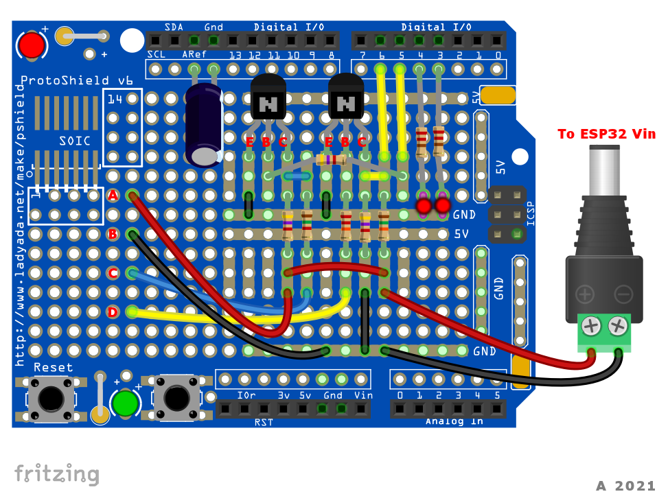
    How do you plan make the interface - I found the prototype shields make a nice neat solution.

    SolderedBoard.png?raw=true

    “Roll it back”


  • Registered Users Posts: 43 gg3390


    Thanks for the reply.

    I have quite a number of ESP32's about the house already, so have made up some adapter boards from vero and headers, so will be easy to add the serial interface and power.
    Also I've dabbled previously with making my own PCB's, but after designing a Z80 microcomputer board I found using KiCAD or EasyEDA together with cheapo boards from somewhere like jlpcb makes for an easy and very professional outcome.
    Assuming of course one gets the schematic right first time, and you're prepared to wait a few weeks for the boards from China...

    Thank you again - I'll retry once I build up the interface.

    Regards
    Ger


  • Registered Users Posts: 43 gg3390


    Hello,
    Just a quick update - built the alarm interface, and this aspect worked very well for me.
    Unfortunately though it looks like I'm hit with a similar problem to previous posters with integration into my CD95 panel - while I can see panel activity, especially if I set the esp32 as the same ID as an existing remote, I cannot add the esp as an RKP - the panel refuses to recognise it on any ID. Although I'm not enough of an expert by any means to glean timings from the current code, it appears from others comments that timing differences on this panel are probably the cause of this.
    So for now I'm going to just implement a simple arm/disarm and printer output monitor. This will more than suffice for looking at logs and remote arm/.disarming.
    Thanks to Ozmo and other for their input, and if anybody else has ideas on how the timings might be changed in the code I'd love to try it.
    Ozmo, you mentioned previously that you might publish the reverse-engineered serial protocol for these panels - did you ever get around to do this? I would not mind understanding the hex values I'm seeing from my panel, but moreso the serial values being transmitted out by the esp32. In my case I'm not sure if they are actually correct (from my limited knowledge and investigations). No worries if not.

    Thanks all.
    Ger


  • Registered Users, Registered Users 2 Posts: 3,876 ✭✭✭ozmo


    gg3390 wrote: »
    ..I'm hit with a similar problem to previous posters with integration into my CD95 panel - while I can see panel activity, especially if I set the esp32 as the same ID as an existing remote, I cannot add the esp as an RKP - the panel refuses to recognise it on any ID.

    ...you mentioned previously that you might publish the reverse-engineered serial protocol for these panels - did you ever get around to do this?

    CD95 is not a panel I use in my house - as the CD95 panel I own has no proper heat sink I can only run it for a short time before it overheats :O
    But Ill set it up again and see what the issue is and get back to you.

    The RKP protocol is fairly well documented in the RKP.cpp file -
    pm me if there are any questions and I can discuss.
    Cheers!

    “Roll it back”


  • Registered Users Posts: 43 gg3390


    No problem - and thanks again for your assistance and efforts on this.

    Regards
    Ger


  • Registered Users Posts: 8 MrWickerman


    Hi,

    I have just been reading through this thread - Ozmo, great job – I love it :)

    I followed your description but I ended up burning the fuse on the panel a few times so maybe this a good time to ask for an advice. I have an Aritech CS351 panel, CD3008 keypad and are using a Mega+WiFi R3 ATmega2560+ESP8266. I have 1 months of experience with Arduino and Aritech so be kind 😉

    What have I done:

    • Build the “two transistor interface board - connects to 12v ABCD keypad socket” but something is not working out for me.
    • Reworked the code from: CastleAritechArduinoRKP-master and CastleAritechArduinoESP32-master to fit my needs.
    • I am able to send Json formatted data from ATmega2560 -> ESP8266 and upload it to an API enabled application in cloud.
    • Managed to get below printed so I can’t be too far away from a solution:

    DUMP_RAW_LINE_DATA:

    • B2 CD 2E 38 D2 00 00 03 E0 87 88 20 17 29 00 00 13 A0 09 13 CF 00 00 23:...8.........).........#
    • A1 20 20 20 20 20 43 53 33 35 31 20 20 56 33 2E 38 C2 00 00 33 A1 20 20:......CS351..V3.8...3...
    • 20 20 20 43 53 33 35 31 20 20 56 33 2E 38 D2 00 -- -- -- -- -- -- -- --:...CS351..V3.8..########
    • 00 07 E0 87 88 20 17 2D 00 00 13 A0 09 13 CF 00 00 23 A1 20 20 20 20 20:.......-.........#......

    DISPLAY_ALL_PACKETS:

    • #0)07 E0 09 13 03 00 -- -- -- -- -- -- -- -- -- -- -- -- -- -- -- -- -- --:......##################
    • #1)13 A0 09 13 CF 00 -- -- -- -- -- -- -- -- -- -- -- -- -- -- -- -- -- --:......##################
    • #2)23 A1 20 20 20 20 20 43 53 33 35 31 20 20 56 33 2E 38 C2 00 -- -- -- --:#......CS351..V3.8..####
    • #3)33 A1 20 20 20 20 20 43 53 33 35 31 20 20 56 33 2E 38 D2 00 -- -- -- --:3......CS351..V3.8..####


    Question 1)

    I have looked at your diagram ‘CircuitAndPerformanceAnalysis.jpg’ and from what I can tell, the signals are negated.

    E.g., when PnlTx goes high => ArdRx goes low – is that intentional and how/where is that handled?

    E.g. ~(00001111) = (11110000)

    If this is it: PORTB &= ~(_BV(0));  //cbi(PORTB, 0);

    How is it handled sending data back?


    Question 2)

    I have a CS351 panel (not CS350). Do you know if the communication bus is the same?

    Using a Voltmeter, I get readings like:

    PnlTx: 6.90 - 7.22V

    PnlRx: 0.09 - 1.23V (seems low). I have a feeling that this is the reason

    I’m waiting for my oscilloscope to arrive to get exact readings.

    Is there other things I can do to validate?


    Question 3)

    I have a ReadDatabus() function call in main loop to read incoming data (similar to your RKPClass::Poll(); in ESP project).

    bool RemoteKeypad::ReadDatabus()

    {

     …

      while (Serial1.available()) //yes - two...make sure we loop until all bytes gone

            while (Serial1.available())

            {

                byte rx = Serial1.read();

                //uart_read_bytes(uart_num, &rx, 1, 0);


                if (bReceivingPacketNow == false)

                {

    Main reason for using this is that I struggle to understand the Interrupt version in CastleAritechArduinoRKP.

    Do you know if above ESP32 approach can be used or would you recommend interrupt version from RPK project? Pros/cons?


    Question 4)

    What is triggering below function to be called in RPK projekt?


    #if defined(UART1_RX_vect)

    ISR(UART1_RX_vect)

    #elif defined(USART1_RX_vect)

    ISR(USART1_RX_vect)

    #elif defined(USART_RX_vect)

    ISR(USART_RX_vect) //UNO has no Serial1

    #else

    #error "No Serial Port?"

    #endif

    {

        static int msgbufLen = 0;

        static byte msgbuf[ixMaxPanel];

        static bool bReceivingPacketNow = false;

        static byte lastByte=-1;


        //Note - nothing here is to be blocking

        //- so sending emails must not block receiving serial logs

        byte rx = UDR;

        if (bReceivingPacketNow == false)

        {

            if(lastByte == 0)

            {//last char was a zero - this was the end of the last message

                if (rx==0)

                    return; //CD34 sends 0 at s


  • Registered Users Posts: 8 MrWickerman


    Small update from my end.

    I have managed to get the CastleAritechArduinoRKP-master work on pnlTx channel.

    I can read messages, example (text in danish):

    0)07 A0 90 53 79 73 74 65 6D 20 46 72 61 6B 6F 62 6C 65 74 76 00 -- -- --:...System.Frakobletv.###

    0)06 A0 90 46 6F 72 6C 61 64 20 6F 6D 72 E5 64 65 20 6E 75 AD 00 -- -- --:...Forlad.omr.de.nu..###

    The Arduino Interrupt thing is slowly starting to make sense. I just can't stop wondering if it is needed/better then 'while (Serial1.available() > 0))'?


  • Advertisement
  • Registered Users, Registered Users 2 Posts: 3,876 ✭✭✭ozmo


    Hi - Ill try answer all the questions..

    1. Board - I've found the ESP32 to be the best - its crazy fast and has lots of memory and wifi - the mega and a ethernet shield should be fine too. But the esp32 can send emails via gmail - the mega doesnt support ssl so it cannot. also the ESP32 is very cheap - way less than 10 euros. And you can get a really cheap ice debugger to step through the code - all not so easy on the arduinos.
    2. Build the circuit - you can either build the circuit or connect directly to the panel (*using very short wires*). Maybe test using direct connect to ensure its working - then build the circuit?
    3. Sending to cloud - without a multithreaded environment this might take too much time to complete and the panel will give errors if it doesn't get a response to a message packet almost immediately.
    4. "Managed to get below printed." Thats great - that means you are successfully receiving good data from the panel. That looks good.
    5. "the signals are negated" - that's correct, the ABCD keyboard bus hardware in the panel expects the signal to be inverted (0v = 1, 12v = 0) - the transistor in the circuit inverts the signal from the arduino - two transistors one for rx and one for tx - if you connect directly to the panel microprocessor chip using the diode, this bypassess that bus electronics and then the signals are Not required to be negated.
    6. Using voltmeter - could be ok - the voltage doesn't need to be exactly 0 or the max voltage for it to be registered as a 0 or 1. Oscilloscope is great to have.
    7. "while (Serial1.available())" - when a byte arrives - we need to spend all the time needed to get the whole packet and respond to it immediately. It would be bad to get half a packet and then exit function and wait for next time in there to get the rest of the packet - we might take too long to respond to the message - three or four missed packets causes a message "keypad disconnected" to appear on the aritech panel.
    8. "the Interrupt version" - every time a byte arrives the arduino calls our function and we store the bytes until we detect its a whole complete message. This means we dont have the overhead of "polling" or constantly asking "are we there yet" of the uart - it will tell us when something has arrived. If you look at earlier versions in the git history - you can see I did use polling originally in the arduino just like you are trying now, but the interupt way made it respond quicker and didnt block the http server and email sending code - The esp32 is using a multithread approach and its cpu is much faster, it doesnt need to use interrupt way. Of the 3 - polling,interrrupt and multithreads - I prefer the esp32 multithreaded way.
    9. "What is triggering below function" - ISR(USART_RX_vect) is called by the arduino - you just need to define it in the code and it will be called - its triggered by the hardware receiving 1 or more bytes
    10. "I just can't stop wondering if it is needed/better then 'while (Serial1.available() > 0))'?" - both are fine, I had both working, you can check the git history for the other version - The interrupt version was slightly quicker to respond and so helped make it work with more panels like the CD92 which has an especially short time available to respond.

    I'd recommend getting an esp32 to play with also - it has more features like Gmail and experimental Amazon Alexa support and there is much more space for experimenting with adding more html etc.

    all the best...

    “Roll it back”


  • Registered Users Posts: 8 MrWickerman


    Hi ozmo,

    Thank you so much for the answer. I have a few things to work with :)

    My solution is build in a slightly different way compared to you.

    I'm using a 'MEGA R3+WiFi ATmega328P+ESP8266 32Mb Memory' board. Build in ESP8266 on Mega board.

    ATmega2560:

    • Send/Receive messages from comm. bus (Serial1)
    • Send/Receive messages from ESP8266 (Serial3)
    • Analog read from sensors

    ESP8266:

    • Send/Receive messages from ATmega2560 (Serial)
    • Connected to WiFi
    • OTA
    • Communication with cloud application (SSL enabled API, JSON)
    • Network scan looking for 'friendly' devices (mobile phones) connected to local network
    • Logging
    • etc.

    Cloud App:

    • Data storage, storing sensor data etc.
    • Connected to mobile app

    However, I will get a ESP32 for comparison and see if it makes life easier or at least more speedy :)

    thanks again


  • Registered Users Posts: 8 MrWickerman


    Hi Ozmo,

    Thanks again for pointing me in the right direction. With your great work I am getting close to a working solution :)

    I get all messages from my CS351 panel and can show them on my web-keypad. I am storing all messages in a database which allows me to show latest movement etc.

    However, I am struggling to make my keypad work alongside the original keypad (CD3008).

    If I disconnect the CD3008 and connect my keypad with ID 1 (RKP_ID: 0) and everything works.

    When I go to the 'Install Panel menu' and connect my keypad with ID 2, 3 or 4 the warning LED turn on and the CD3008 freezes (can't press any keys).

    Is there a special order I should follow when installing my keypad?

    This is what I do:

    1. I connect my Arduino keypad to the comm. bus (excluding Tx port). I do this while power is on.
    2. I navigate to the tech menu 'install panel' using CD3008. The display text is: Panels p***.
    3. I connect the Tx from my Arduino.
    4. The CD3008 panel text changes to: Panels pp**. Shortly after the CD3008 are turning on/off with a 'click' sound and the display text changes to: Panels *P**, the warning LED turns orange and the panel freezes. At this point in time I am unable to use any of the keypads. I can see that ACK messages are send from the Arduino to the panel (12 00 00 12).


    Post edited by MrWickerman on


  • Registered Users Posts: 8 MrWickerman


    A completely differing topic/question.

    I bought a cheap oscilloscope DS211 as you suggested in one of your earlier posts - which has been crazy helpful.

    From that I can see that there seems to be a small delay between each byte send by the original keypad. The delay is not there when sending messages from the Arduino board. Did you solve that somehow?

    Yn: Messages send from Arduino

    Ex: ack (02 00 00 02) send by CD3008.


  • Registered Users Posts: 8 MrWickerman


    Last post updated

    Post edited by MrWickerman on


  • Registered Users Posts: 8 MrWickerman


    Last post updated


  • Registered Users, Registered Users 2 Posts: 3,876 ✭✭✭ozmo


    Oh - just noticed this - this new site update.. - Im not getting notifications always of this and other threads - dont know why...

    Do you still have the problem?

    To make those traces match more closely - maybe can you try changing the baud rate setting on the arduino a tiny bit faster and do another test with the oscilloscope.

    #define nSerialBaudKP_RX 1953 <--- increase this number by 1 to 10 and see if that helps...

    “Roll it back”


  • Registered Users Posts: 21 Vasarbob


    Hi Ozmo,

    I have made the transistor pcb with a uno and connected it to the HKC panel . All good there . Installed it on the panel as a keypad and it shows up as finding 4 ( i have 3 keypads connected to the panel so that is the uno showing up as the forth) so that is ok too. Problem is i can log into the keypad but nothing is showing up on the small screen. I can press the keys but nothing shows up. I checked the html with the developer tool on chrome and it shows up this as a problem . Is this java that is not loading ? Any ideas would be great


  • Registered Users Posts: 21 Vasarbob


    s what the error is. sorry but it wont let me post links on the forum yet.


  • Advertisement
  • Registered Users Posts: 21 Vasarbob


    Also Mr Wickerman,

    How did you get on with the keypad freezing when you connected it. I have the same problem but I am using the HKC panel. keypads freeze , yellow light ect.


Advertisement