Advertisement
If you have a new account but are having problems posting or verifying your account, please email us on hello@boards.ie for help. Thanks :)
Hello all! Please ensure that you are posting a new thread or question in the appropriate forum. The Feedback forum is overwhelmed with questions that are having to be moved elsewhere. If you need help to verify your account contact hello@boards.ie

Solar Panel Project For School

2

Comments

  • Registered Users Posts: 1,207 ✭✭✭bungaro79


    Brilliant. Thanks for that. I'll try that over the next few days when there's hopefully a bit of good sunshine here!


  • Registered Users Posts: 1,207 ✭✭✭bungaro79


    Tried to put a load on the buck convertor (but not sure if I did it right!) and unfortunately I didn't seem to get any reading


  • Registered Users Posts: 6,583 ✭✭✭10-10-20


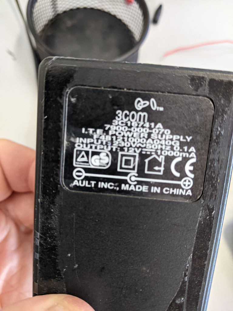
    Doh! You'll have to test it using a bench power-supply or a 12v supply with a 2.5mm jack.

    Just feed in 12v and connect that resistor (100 ohm) up to the output screw-terminals directly (ditch the wires for the moment). Then with the multi-meter (MM), measure the input voltage off the top of the screw-terminals (just to check that the MM is working) and then test the output the same way too (should see 5v). If you don't see 5v, you may have a dud buck converter.


  • Registered Users Posts: 1,207 ✭✭✭bungaro79


    After googling "bench power supply" (this is the level of novice you're dealing with :D ) and searching around the house for a 12v supply (most of the plugs with the 2.5mm jack seem to be only 6v) I came up with nothing so I'll have to wait till Monday when I can check back in school where I'm pretty sure I have a 12v supply lead.

    Thanks for the basic steps in how to test. Really looking forward to showing the class all about this once I finish testing this. Going to use the lovely sunshine today to link up the two panels I have in series and parallel and see if I get the hang of it!


  • Registered Users Posts: 6,144 ✭✭✭The Continental Op


    House 12V supply - car battery? OK so its going to be a bit over 12 V but I did see one in one of your earlier pictures.

    Wake me up when it's all over.


  • Advertisement
  • Registered Users Posts: 1,207 ✭✭✭bungaro79


    I didn't think of that as a testing source! But I actually left it in school with the inverter and charge controller as I'm still waiting on the solar panels.

    So if I do try and use that 12v battery as my testing current, what kind of connection would I use from the battery? I've been looking online to see something with two wires that comes off the battery and goes into the barrel jack but can't seem to find anything.


  • Registered Users Posts: 6,144 ✭✭✭The Continental Op


    I was only thinking of the 12V battery as a lateral thinking type of source of power.

    I'd use one with big battery type crocadile clips and a circuit with a fuse in it. FUSE is important! You have a store of power that you don't want to dump into a short circuit without some protection.

    You can also use any battery terminals, loads on Amazon but as I said don't forget the fuse, you can't turn a battery off like a power supply plugged into a socket.

    Amazon has loads of cheap bench power supplies for example https://www.amazon.co.uk/Adjustable-Switching-Precision-Charging-Interface/dp/B09C8LWV9W/ handy as they are normally over current protected and you can dial up whatever voltage you require for testing.

    Wake me up when it's all over.


  • Registered Users Posts: 1,207 ✭✭✭bungaro79


    I think getting a 12v plug might be easier so! Thanks for the info though. Great to get all the advice


  • Registered Users Posts: 6,583 ✭✭✭10-10-20


    We'll make an electronic engineer out of you yet.

    Most routers or internet boxes have 12v supplies with 2.5mm plugs. That's if you can live without internet while testing this. ;)


  • Registered Users Posts: 6,144 ✭✭✭The Continental Op


    OP if you are making up "experiments" then these plugs for low voltage stuff might be handy for making up cables https://www.amazon.co.uk/LightingWill-Barrel-Connector-Adapter-Security-10Pair-Female-Male-DC-adaptor/dp/B077YGV3F4/ . That size connector is fairly universal and fits a lot of 12V (and other) wall wart power supplies making the connections available as two screw terminals. You'll note it's also the same size connection on the buck convertor. There are lots of other possible cable plugs you can use but sometimes its easier to get away from crocodile clips particularly if you want the polarities to be right each time.

    Edit> Just a thought you could do a class request for any old unused power supplies might net you a few useful ones?

    Wake me up when it's all over.


  • Advertisement
  • Registered Users Posts: 6,583 ✭✭✭10-10-20


    I'd be wary of "any old power-supplies" these days. BigClive has been an eye-opener in that respect.


  • Registered Users Posts: 1,207 ✭✭✭bungaro79


  • Registered Users Posts: 1,207 ✭✭✭bungaro79


    Great stuff. I'll take any recommendations ye give me!


  • Registered Users Posts: 1,207 ✭✭✭bungaro79


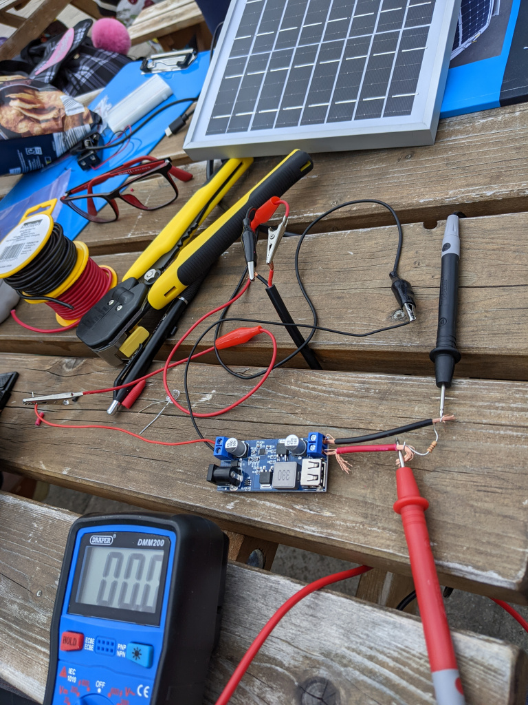
    So, I only got around to testing the buck convertor today as it's been manic with school tours and sports days and all the end of year stuff!

    I found an old 12v charger from our coderdojo router. I put in the 100 ohm resistor and plugged in the charger and then the smoke came 😂

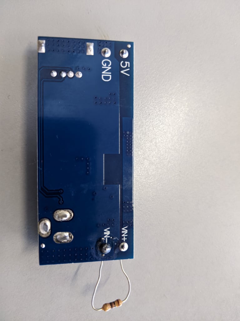
    Does the set up below look ok?!?!


  • Registered Users Posts: 6,583 ✭✭✭10-10-20


    Did you mean to have the resistor on the 12v input of the power-board? That barrel connector and the "VIN-VIN+" are directly connected.

    100 ohm @ 12v = (120mA / 1.44W) = smoke. (a fully balanced equation ;) )

    So yes, that was expected as that resistor is probably rated at 0.25W and you put 1.44W through it. That's fine as a test of 12v.

    Now put a 100ohm resistor on the 5v output of the power-board. It should still heat up, but you'll only be putting in 0.25W (50mA).

    If you can then measure 5v on the output of the board, then it confirms that the board is ok!

    https://ohmslawcalculator.com/ohms-law-calculator


  • Registered Users Posts: 1,207 ✭✭✭bungaro79


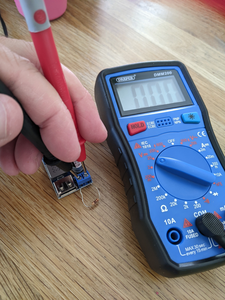
    Ok. Think I did it correctly this time 😅

    It's coming out at 0 reading on the multimeter


  • Registered Users Posts: 6,583 ✭✭✭10-10-20


    If you have 12v on the input and even with a blown resistor there, you should be seeing 5v on the output. I'd suggest that you have a blown DC to DC converter board. 😕

    Maybe no fault of you own. That's why I usually buy two of those at a time.


  • Registered Users Posts: 1,207 ✭✭✭bungaro79


    Cool. Think I'll return it so and order two like you recommended.


  • Registered Users Posts: 1,207 ✭✭✭bungaro79


    Just to keep me tipping away I'm trying one other little project!

    I saw a solar powered clock on instructables.com and it looks really interesting as it uses a super capacitor to power it.

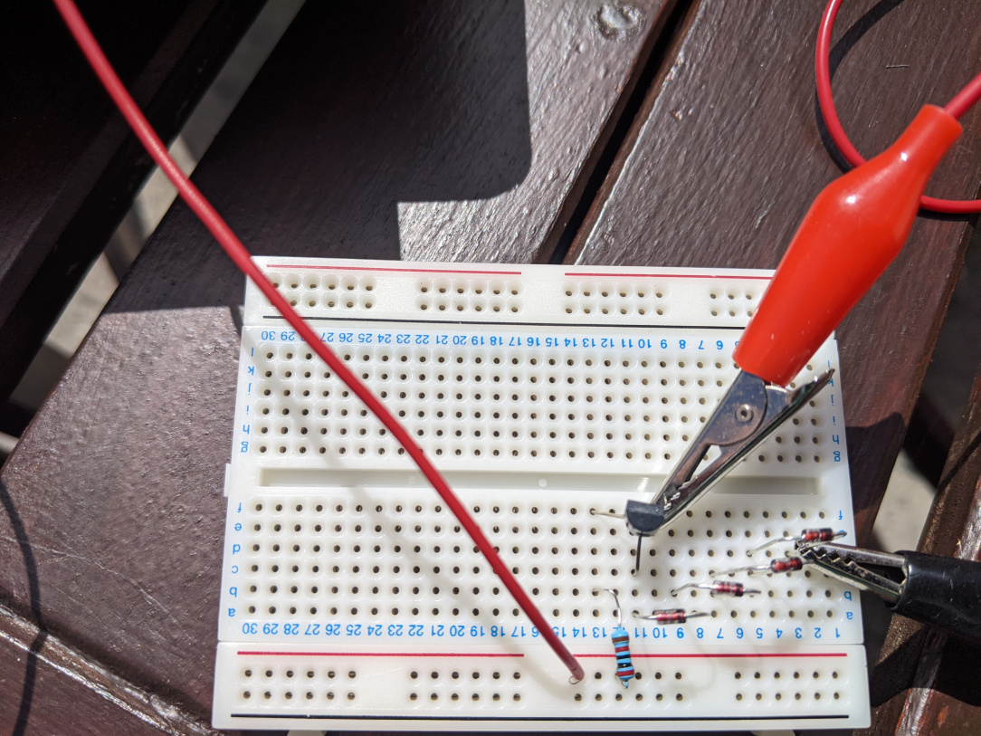
    I think I've the set up correct but can anyone cast their eye over this and see if my set up is right? Hoping to bring it into the class next week while I'm waiting on the new buck convertor and the solar panels


  • Registered Users Posts: 1,207 ✭✭✭bungaro79


    I don't need to hook up the supercapacitor to the clock until its fully charged according to the instructions. I also had to use a 20k resistor as I didn't have any 22k ones.


    https://www.instructables.com/How-to-Run-a-Battery-Clock-on-Solar-Power/


  • Advertisement
  • Registered Users Posts: 1,207 ✭✭✭bungaro79


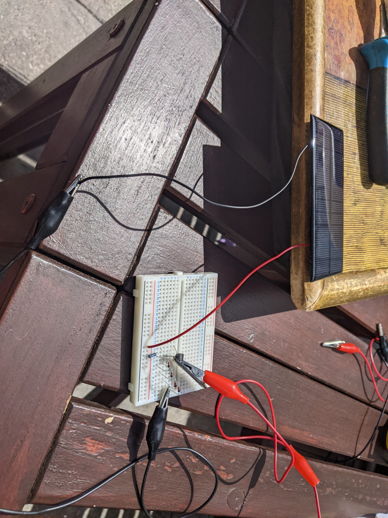
    3 months later my solar panel arrives! Unfortunately we are finishing up tomorrow 😬

    Hopefully I'll get a bit of sunshine tomorrow to get the lads to see it in action!


  • Registered Users Posts: 6,144 ✭✭✭The Continental Op


    Don't forget to get that lead acid battery (picture in post 24) fully charged up before the holiday so its not dead when you come back.

    Wake me up when it's all over.


  • Registered Users Posts: 6,583 ✭✭✭10-10-20


    A bit late now, but that circuit isn't right. The 20k ohm resistor should be connected between two pins of that transistor, at the moment it's only connected to the 'base' (the 'control' of the gate) and is missing the + supply off the mini solar panel.

    If you move the red + wire onto row 13 that will connect it up and then move the opposite resistor's lead from the horizontal supply side of the breadboard and into row 11, then it will be correct. The black - lead from the panel should then go into the bottom of that stack of diodes (row 2?) and the capacitor connected up using the crocodile clips.

    While the voltages here are low, be careful of capacitors such as that - it's very easy to short the terminals using a watch or ring and end up with a burn. Not a serious consideration with 1.5v, but if the voltage goes higher (maybe such as greater than 24v) then it is a problem.


  • Registered Users Posts: 1,207 ✭✭✭bungaro79


    Cheers 10-10-20. Just back from the hols so I'll have a proper look at it again over the next couple of days. I'm after ordering a few more of the buck convertors and some with digit displays so it'll be good to play around with them. I'm thinking that maybe instead of using the bread board set up, I might get an adjustable convertor and try that instead.


  • Registered Users Posts: 1,207 ✭✭✭bungaro79


    Hi all

    Finally getting around to testing this out properly! I have been using Will Prowse's book to make sure the sizes are right and I think it's ok. I'm thinking I need a fuse on the positive wire between the battery and the inverter, right? The charge controller has a 20A fuse in it so I'm thinking that's enough for that?

    Appreciate the great info and advice on here as usual!


  • Registered Users Posts: 6,144 ✭✭✭The Continental Op


    If you don't have them these fuse holders are handy on the low voltage side https://www.amazon.co.uk/gp/product/B00904ND2E/

    Wake me up when it's all over.


  • Registered Users Posts: 1,207 ✭✭✭bungaro79


    I did buy one of those actually but its one of the only things I've left in school! Not sure if its open so in the mean time could I just put a bolt in each side of the fuse and put one into the battery and the other on the end of the positive wire going to the inverter?


  • Registered Users Posts: 6,144 ✭✭✭The Continental Op


    If you want to get the max out of the battery without killing it. Then this is very useful Victron Energy Smart Battery Protect 12/24 Volt 65 Amp (Bluetooth) Battery Protection you can set it to turn off the power when the battery gets to half charge which is a low as you can go regularly without damaging the battery. Some inverters have that built in. There is a cheaper non bluetooth version .

    Just a thought on practical school applications. If you just stick to a well fused 12V system and suitably encase the components you could set up a class charging station for low voltage devices with a small bank of USB chargers.

    Wake me up when it's all over.


  • Registered Users Posts: 1,207 ✭✭✭bungaro79


    That's fantastic, thanks for the heads up. That's exactly what I'm trying to setup in the class room! Does my set-up look alright otherwise Continental?


  • Advertisement
  • Registered Users Posts: 6,144 ✭✭✭The Continental Op


    Nothing wrong I can see, I'd also have each group, solar, battery and mains both switchable and fused. You don't want to be electrocuting someone or have sparks flying and be looking around for a 10mm spanner or waiting for a fuse to blow.

    Wake me up when it's all over.


Advertisement