Advertisement
If you have a new account but are having problems posting or verifying your account, please email us on hello@boards.ie for help. Thanks :)
Hello all! Please ensure that you are posting a new thread or question in the appropriate forum. The Feedback forum is overwhelmed with questions that are having to be moved elsewhere. If you need help to verify your account contact hello@boards.ie
Hi there,
There is an issue with role permissions that is being worked on at the moment.
If you are having trouble with access or permissions on regional forums please post here to get access: https://www.boards.ie/discussion/2058365403/you-do-not-have-permission-for-that#latest

Solar Panel Project For School

2»

Comments

  • Registered Users, Registered Users 2 Posts: 1,213 ✭✭✭bungaro79


    3 months later my solar panel arrives! Unfortunately we are finishing up tomorrow 😬

    Hopefully I'll get a bit of sunshine tomorrow to get the lads to see it in action!


  • Registered Users, Registered Users 2 Posts: 7,185 ✭✭✭The Continental Op


    Don't forget to get that lead acid battery (picture in post 24) fully charged up before the holiday so its not dead when you come back.

    Wake me up when it's all over.


  • Registered Users, Registered Users 2 Posts: 7,716 ✭✭✭10-10-20


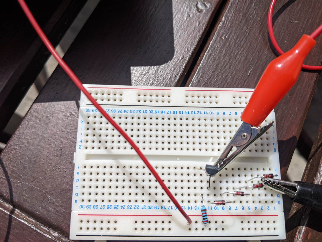
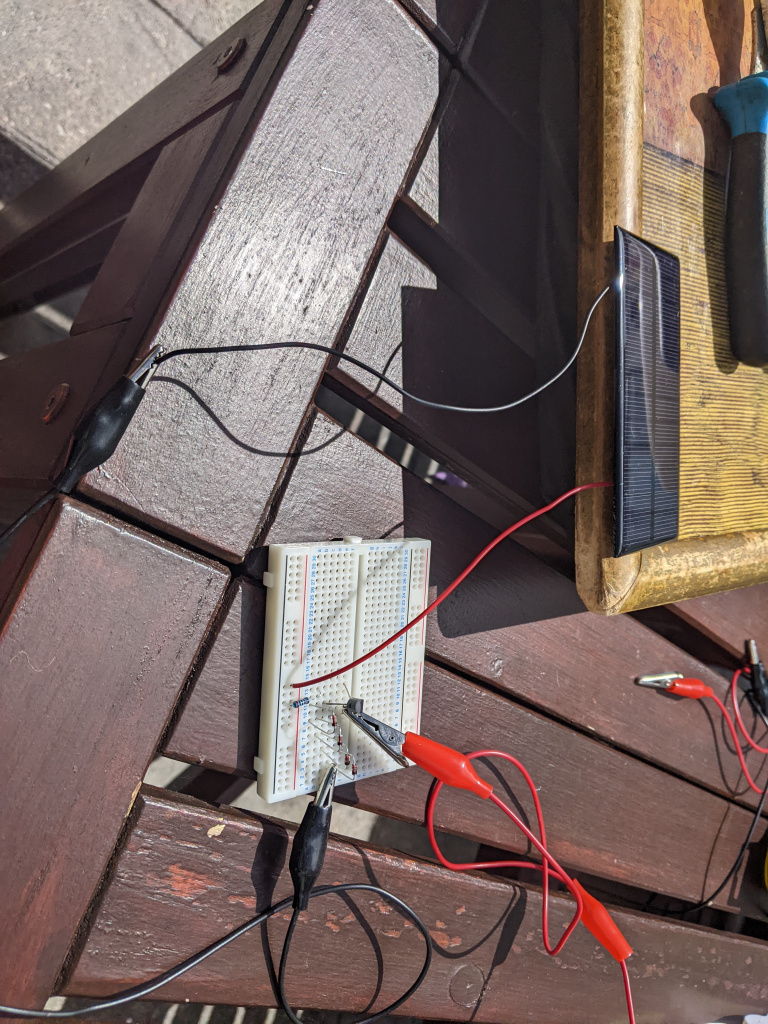
    A bit late now, but that circuit isn't right. The 20k ohm resistor should be connected between two pins of that transistor, at the moment it's only connected to the 'base' (the 'control' of the gate) and is missing the + supply off the mini solar panel.

    If you move the red + wire onto row 13 that will connect it up and then move the opposite resistor's lead from the horizontal supply side of the breadboard and into row 11, then it will be correct. The black - lead from the panel should then go into the bottom of that stack of diodes (row 2?) and the capacitor connected up using the crocodile clips.

    While the voltages here are low, be careful of capacitors such as that - it's very easy to short the terminals using a watch or ring and end up with a burn. Not a serious consideration with 1.5v, but if the voltage goes higher (maybe such as greater than 24v) then it is a problem.


  • Registered Users, Registered Users 2 Posts: 1,213 ✭✭✭bungaro79


    Cheers 10-10-20. Just back from the hols so I'll have a proper look at it again over the next couple of days. I'm after ordering a few more of the buck convertors and some with digit displays so it'll be good to play around with them. I'm thinking that maybe instead of using the bread board set up, I might get an adjustable convertor and try that instead.


  • Registered Users, Registered Users 2 Posts: 1,213 ✭✭✭bungaro79


    Hi all

    Finally getting around to testing this out properly! I have been using Will Prowse's book to make sure the sizes are right and I think it's ok. I'm thinking I need a fuse on the positive wire between the battery and the inverter, right? The charge controller has a 20A fuse in it so I'm thinking that's enough for that?

    Appreciate the great info and advice on here as usual!


  • Registered Users, Registered Users 2 Posts: 7,185 ✭✭✭The Continental Op


    If you don't have them these fuse holders are handy on the low voltage side https://www.amazon.co.uk/gp/product/B00904ND2E/

    Wake me up when it's all over.


  • Registered Users, Registered Users 2 Posts: 1,213 ✭✭✭bungaro79


    I did buy one of those actually but its one of the only things I've left in school! Not sure if its open so in the mean time could I just put a bolt in each side of the fuse and put one into the battery and the other on the end of the positive wire going to the inverter?


  • Registered Users, Registered Users 2 Posts: 7,185 ✭✭✭The Continental Op


    If you want to get the max out of the battery without killing it. Then this is very useful Victron Energy Smart Battery Protect 12/24 Volt 65 Amp (Bluetooth) Battery Protection you can set it to turn off the power when the battery gets to half charge which is a low as you can go regularly without damaging the battery. Some inverters have that built in. There is a cheaper non bluetooth version .

    Just a thought on practical school applications. If you just stick to a well fused 12V system and suitably encase the components you could set up a class charging station for low voltage devices with a small bank of USB chargers.

    Wake me up when it's all over.


  • Registered Users, Registered Users 2 Posts: 1,213 ✭✭✭bungaro79


    That's fantastic, thanks for the heads up. That's exactly what I'm trying to setup in the class room! Does my set-up look alright otherwise Continental?


  • Advertisement
  • Registered Users, Registered Users 2 Posts: 7,185 ✭✭✭The Continental Op


    Nothing wrong I can see, I'd also have each group, solar, battery and mains both switchable and fused. You don't want to be electrocuting someone or have sparks flying and be looking around for a 10mm spanner or waiting for a fuse to blow.

    Wake me up when it's all over.


  • Registered Users, Registered Users 2 Posts: 1,213 ✭✭✭bungaro79


    Good to know it looks alright! Really appreciate all the help. Looking forward to making the last few changes like you mentioned to make it fully safe to bring into the classroom and be able to show my students how we can use solar to power things around the class.


  • Registered Users, Registered Users 2 Posts: 7,185 ✭✭✭The Continental Op


    On the safety side this is an interesting video. I know you aren't going to do this but when working with kids you never quite know what they might do.


    Wake me up when it's all over.


  • Moderators, Home & Garden Moderators Posts: 6,372 Mod ✭✭✭✭graememk


    is that it quite disappointing? Need a better jump lead, that one just melted. Try a 24 spanner ;)


  • Registered Users, Registered Users 2 Posts: 1,213 ✭✭✭bungaro79


    That's actually a great video but I was thinking there would be like a mini explosion if you shorted the battery!


    You mentioned making my setup safe by adding switches as well as fuses. Would you be able to point me in the right direction of something which would be suitable? Cheers


  • Registered Users, Registered Users 2 Posts: 7,185 ✭✭✭The Continental Op


    Think you need to box it - do you have a woodwork class? Failing that measure up the size of the battery or take to your local electrical wholesale supplier and see if they have a suitably sized box mount it in. I'd go for a plastic box with a hinged door better still a hinged transparent door. Fuses can be mounted inside the box and switches on the outside. Use tails coming out of the box for the battery and solar panels. Use MC4 connectors on the solar panel connectors https://www.amazon.co.uk/photovoltaic-connector-Waterproof-Connector-connection/dp/B08GCYGZ94/ and if you need a quick connector for the battery side (up to 50 Amp) I think Anderson connectors are handy https://www.amazon.co.uk/CESFONJER-Connector-Connectors-Disconnect-Motorhome/dp/B0832MT3KW/. More added cost though as you'll need separate crimping tools for the MC4 and Anderson connectors. I use this crimping tool with a lump hammer for the battery connections https://www.amazon.co.uk/gp/product/B0108AIZZ8/ (price is a bit high I only paid £15). You'll also need a tool for the MC4 connectors.

    A battery box something like this might also be helpful then you can mount the switches on the case https://www.amazon.co.uk/NOCO-HM300BKS-HM300BK/dp/B004W5SFYW/ . Here's one idea what a finished boxed battery could look like https://www.amazon.co.uk/Qiilu-Trolling-Portable-Accessary-Voltmeter/dp/B09DFJCPJ7/ . Another option would be a good strong plastic tool box.

    Switches are a bit of a pain to mount on the battery side as the cables are really thick but these seem to get used a lot https://www.amazon.co.uk/Battery-Disconnect-Switch-Isolator-Vehicle/dp/B081CYGFN6/ or if you are mounting in a panel these https://www.amazon.co.uk/Techniks-BS01-Battery-Isolator-Switch/dp/B009CRM34I/

    A lot of added complication and expense and not everyone would do it my way (probably not many ;-) ) so think it over well before you decide what to do.

    Obviously if you are going to use the unit for charging USB chargeable devices etc then you can fit those components on a suitable case.

    Wake me up when it's all over.


  • Advertisement
  • Registered Users, Registered Users 2 Posts: 1,213 ✭✭✭bungaro79


    Great info there! Unfortunately since I'm in a primary school we don't have access to metalwork or woodwork tools and resources! I really appreciate all the links you posted. On the solar panel there are already MC4 connectors and I have extended ones (https://www.amazon.co.uk/gp/product/B00DGXVO80/ref=ppx_yo_dt_b_search_asin_title?ie=UTF8&psc=1) which are really handy for plugging straight into the control charger. But the best part of them is that I can just disconnect them in the middle when I need to move the setup and at least that makes carrying it easier. I do have a good crimping set but the ones you mentioned looked great too and have been added to the wishlist!

    I think I'll have to go down the cheap route for the box. But I will get a sturdy one and drill holes where I need too. Those switches look great and I think I will end up putting the control charger and inverter on a panel so I'll fit the switch in there too. My electrician friend is going to help me with the final few fitouts so I think come the end of the month, when we're back to school we should be good to go.

    Huge appreciation though for all the help and advice I've received on here.


  • Registered Users, Registered Users 2 Posts: 1,213 ✭✭✭bungaro79


    So I finally got sorted! I have the battery in a covered box (it's really too small, will definitely have to upgrade) but it's working! The class are loving seeing my laptop and anything else charged off of it.

    Thanks to all on here for the help


  • Registered Users, Registered Users 2 Posts: 7,185 ✭✭✭The Continental Op


    You could keep the whole system a little safer and possibly more efficient if you sat at 12 V and get rid of the inverter? You can get a laptop charger that works directly of 12V so you are only going for 12V directly to the laptop voltage (something around 18-20v) rather than going through the additional 12V to 220V AC conversion then 220C to the laptop voltage. Not sure how efficient the 12V laptop chargers are but the ones I have used for netbooks in the car have been useful. https://www.amazon.co.uk/s?k=12V+laptop+charger

    Wake me up when it's all over.


  • Registered Users, Registered Users 2 Posts: 1,213 ✭✭✭bungaro79


    Good idea and not using an inverter was definitely considered! I think I just wanted to have one as the kids would see the daily uses for a working plug. I'm also plugging more things into it but the link for the laptop charger is really good to know


  • Registered Users, Registered Users 2 Posts: 7,716 ✭✭✭10-10-20


    Well done on getting that all completed, hopefully an inspirational project for all.

    Can I just check - from what I can see the inverter is connected directly to the battery? You actually should have the inverter connected into the LOAD section of the MPPT controller. Otherwise what happens is that the MTTP controller will be trying to 'recharge' the battery (state will report BULK charging) at the MPPT) continuously as the inverter will be pulling the voltage, damaging the battery.

    Moving the inverter over to the LOAD will eliminate that and you'll see the load correctly on the app and the MTTP controller will be able to manage the load so that the battery isn't discharged less than ~10v.


  • Advertisement
  • Registered Users, Registered Users 2 Posts: 1,213 ✭✭✭bungaro79


    I did wonder about that when I first started researching the project but nearly everything I saw recommended what I did but I did always think that it was strange that the load connectors on the MPPT weren't being used! It makes sense about what you're saying regarding the battery. When I was monitoring the battery today it never discharged below 12.7v and was going up to 14.1v but I was wondering if the constant draw would be an issue


  • Registered Users, Registered Users 2 Posts: 7,716 ✭✭✭10-10-20


    Yes, it would be a big issue over a period of about a few weeks as that sealed lead-acid battery can't take many deep-discharges.


  • Registered Users, Registered Users 2 Posts: 7,185 ✭✭✭The Continental Op


    You only get those extra load connections on controllers that are around 20 Amps or less. Its a handy "free" feature you have to pay extra for on larger controllers.

    I'm not sure how much control you have over setting the voltage that switches off the load but the literature says

    Low voltage load disconnect 11,1V or 11,8V or Battery Life algorithm 

    Low voltage load reconnect 13,1V or 14V or Battery Life algorithm

    edited from https://www.victronenergy.com/upload/documents/Datasheet-SmartSolar-charge-controller-MPPT-75-10,-75-15,-100-15,-100-20,-100-20_48V-EN.pdf

    However Victron normally give you more than enough parameters that are adjustable.

    Wake me up when it's all over.


  • Registered Users, Registered Users 2 Posts: 1,213 ✭✭✭bungaro79


    Good to know. I did notice that the bigger amp models didn't have those extra connections so I'll definitely hook the invertor up to it!


  • Registered Users, Registered Users 2 Posts: 436 ✭✭Girl Geraldine


    Does your principal know and understand what you are doing with the students?

    Are they aware of the risk of shock and fire and have ye controls and things in place to ensure safety?

    My school wouldn't be entertaining these sort of experiments with 220V.


  • Registered Users, Registered Users 2 Posts: 7,185 ✭✭✭The Continental Op


    There is no "experiment" with 220V. Obviously safer not to have 220V but the only 220V connection is one socket on the inverter. No other connections that are 220V, nothing kids could get fingers into and nothing more dangerous than plugging a mains device into any 220V socket in a classroom. Far more danger from the 12V side if someone shorted out the connections, hence my earlier comments.

    Wake me up when it's all over.


  • Registered Users, Registered Users 2 Posts: 436 ✭✭Girl Geraldine


    Does the principal fully appreciate the nature of this set up? That you have a battery capable of pumping out current sufficient to start a fire or cause bad burns if shorted? And that you have a 220V side of it that can deliver enough current at sufficient voltage to kill.

    Does the school's insurance cover this sort of thing? Are there risk assessments and so on for all this? Has the set up been designed by, or at least inspected by someone who is appropriately qualified to ensure it is safe, and safe to have around children?

    Extra curricular science experiments are all well and good until something goes wrong. Then ye are fúcked and there will be big trouble cos ye will have been going beyond your brief into an area which, as authorities will see it, was totally unnecessary and in which you are totally totally unqualified.

    I think that if the worse happened and someone got a burn off of it, or a shock, of if there was a fire incident, they school and yourself would be in the height of trouble and there would be hell to pay.

    • No safety risk assessments
    • Unqualified staff messing around trial and error with 220V and high current electrical gear.
    • The experiment set up on a carpet and unsecured where kids could, unbeknownst to staff, come in and start inferfering with it. And being an interesting demo, they will be drawn to it with far more interest than a standard 220V wall socket.
    • A solar panel array on the roof that could blow down in a gust of wind and take the head off someone.
    • Whoever put the solar panel on the roof probably doing so in breach of H&S regulations for work at height.
    • They could even throw the book at the school and do them for using equipment that isn't PAT tested.

    Incidentally, on the next round of routing electrical PAT testing at the school, if the tester comes across this they will probably flag it as a hazardous appliance.

    I think you need to stand back here and re-evaluate. A school in 2022 is a very controlled environment with very high bar for "duty of care". It is not Nikolai Tesla's laboratory from the 1910s.


  • Registered Users, Registered Users 2 Posts: 1,213 ✭✭✭bungaro79


    Thanks Geraldine. I appreciate the comments and you obviously seem to have a lot of knowledge in this area so I will absolutely take on board what you've written and re-evaluate the set up and ensure that we can get it working safely in the school. If not, then fair enough, I'll take it down as we obviously don't want anything to happen as a result of it. The principal is aware of it but again maybe doesn't know enough about electrics to know what he was saying yes to.


  • Registered Users, Registered Users 2 Posts: 436 ✭✭Girl Geraldine


    I would say yes, it's possible a principal who doesn't have the knowedge to agree to something when they don't fully appreciate the nature of it and the potential risks.

    This is very, very different from a set of snap-circuits.

    Realistically, to get this abve board you'd have to get an electrician to come in and certify it as safe. I don't know if that is even possible for this type of thing, because it isn't your typical electrical installation.

    Ad-hoc set ups are grand and dandy at home or in your shed, but in a school with children and they way everything is so litigious and that, I wouldn't be taking chances.


Advertisement