Advertisement
Help Keep Boards Alive. Support us by going ad free today. See here: https://subscriptions.boards.ie/.
If we do not hit our goal we will be forced to close the site.

Current status: https://keepboardsalive.com/

Annual subs are best for most impact. If you are still undecided on going Ad Free - you can also donate using the Paypal Donate option. All contribution helps. Thank you.
https://www.boards.ie/group/1878-subscribers-forum

Private Group for paid up members of Boards.ie. Join the club.
Hi all, please see this major site announcement: https://www.boards.ie/discussion/2058427594/boards-ie-2026

Changeover Switches and running off grid via solar/Generator

«1

Comments

  • Registered Users, Registered Users 2 Posts: 1,010 ✭✭✭homewardbound11


    Edit : should have put this on solar for beginners forum . Apologies

    I’m about to get solar installed next week and have asked for a manual change over.

    What should I be expecting as I would like to operate the system with the panels feeding the batteries during an outage of electricity .

    Sorry Deezel ,

    I’m not an electrician but was reading your mail to work out what I should get and added your quote in here .
    is there an earth bond to neutral at the meter and also at the inverter in your system ? Or is neutral broken when using the off grids mode and you are just using the one earth at the meter as neutral ?.

    If anyone can please add a requirements and must list as I’ve 3 days left before install. I don’t want to be feeding the grid in anyway during a power outage, safety first .


  • Registered Users, Registered Users 2, Paid Member Posts: 8,220 ✭✭✭deezell


    My back up is a generator, not an off grid solar, but the same principles apply. Earth and Neutral are permanently bonded at the grid entry point, prior to the meter. When on grid the inverter neutral and live are both connected to the grid, and into the consumer unit. When you change over from on-grid to off-grid, both L and N poles of the grid, after the meter, are disconnected. The inverter is still connected to the consumer unit, and is now the backup supply to it. The inverter will be triggered by an additional change switch contact to initiate off grid operation, otherwise it will stop, as is correct, while its on grid, and the mains are down.

    Because the grid neutral is no longer connected to the consumer unit and inverter neutral, it is necessary to have a another change over contact to connect the inverter and consumer unit neutral back to mains permanent earthing point prior to the meter. Now, because the grid and meter neutral are permanently bonded here anyway, it seems like you're just reconnecting the inverter neutral back to grid neutral, so why disconnect the neutral at all with a change over switch? The answer is that you don't have the Neutral of the off-grid inverter obtaining it's Earth binding via the output neutral of the meter, it must be bonded to the permanent Earth/Neutral prior to the meter. (This is actually just the Earth terminal bar in the consumer unit).

    It's hard to get your head around, and the sparkies in the generator forum were in knots over it. It's probably simpler to understand in terms of using an inverter rather than a genny as backup, (apart for the peculiarly Irish regulation that requires panels to be disconnected automatically during an outage). You need these reconnected to charge your off grid backup battery, so yet another switching arrangement is needed to re-energize the 'fireman switch', 'shunt' or automatic DC isolator, you chose the name.

    . Actually, the Sigen installer guide posted by @KingCong listed two brands of switch for changeover, the diagram included though generic clearly shows the supply lines in three phase, (4 little diagonal lines on the feed and the labels L1, L2, L3, N), but you just can just consider it L1 and N for domestic solar. All thats happens in this diagram is as I described above. The inverter L and N are never disconnected from the consumer unit, but this N has to be rebound to the grid permanent earth when both grid L and N are disconnected in off grid mode. The diagram doesn't account for panel DC isolator restoration, as this is the numpty local thing thats caused so much confusion, but, it doesn't prevent you from actually having panel DC when the mains is out, as according to SEAI input to the RTE segment, you can use your inverters for backup, (if regi installed). Logically that means reconnecting the panels, so you'd wonder what's the point of the isolator in the first place.

    Note that the NADER NDQ2A switch recommended by Sigen is, afaik, motorised, and an (optional) automatic change over breaker, so, (panel DC aside), using this switch could give automatic and instantaneous backup switchover, which is what Sigens own €2 grand box achieves. I must price that NADER, it looks posh. There's a couple of 125A 2pole MCBs and a 63A 2pole MCB in the Sigen Diagram also.


  • Registered Users, Registered Users 2, Paid Member Posts: 8,220 ✭✭✭deezell


    Thats entirely understandable. Something like a small 1kw inverter generator will cost a lot less than adding solar backup, or a hard wired generator. Given it's uncertain complexity, some solar installers wont even go there, and these are qualified electricians. You can just whip this little generator out and run a few extension leads for lights, TV, fridge if the cut is a long one. Very handy to have whenever you might need power somewhere like a picnic, it will run a mini kettle or small coffee maker.

    https://amzn.eu/d/bQyuFYf


  • Registered Users, Registered Users 2 Posts: 216 ✭✭Grey123


    I have something similar from my EV via an extension lead, limited to 3.6kW so some lights, fridge, internet and maybe kettle. Am I correct in thinking that is much bigger than the 1400W attached generator (sounds a stupid question just not sure if its like with like).

    Are there generators that can be plugged in to run the house, we use up to 20kwh in winter, about 10kwh of that is air to water related. Advantage being all lights / sockets and no extension leads with a toddler!

    The EcoFlow is tempting as while 10kwh of battery would only last a half day on average (we obv, wouldn't run the washing machine etc..) it would allow us have all the lights on (I think).


  • Moderators, Home & Garden Moderators Posts: 7,283 Mod ✭✭✭✭graememk


    Spun this out into its own thread,

    But yeah, your only limited by generator size, and how much you want to spend, If running via a generator.

    eg: https://ige.ie/generators

    But responsible use is essential, as there was people who died during eowyn of CO poisoning.

    I have heard from a fireman, that was called out during eowyn to a door that caught fire/melted because the exhaust of the generator and as soon as they entered the house all their CO alarms went off.

    @deezell - I was meant to reply earlier, Ive seen photos of cascade changeover switches too.

    There is a main changeover and then a secondary changeover that switches between inverter and generator.

    The brand new Solis (the one that looks very like a deye/sunsynk, except for the screen) and the deye/sunsynk have a generator input on them.

    You can use this generator input to keep your batteries charged up, so you could run the generator flat out for a hour charge up batteries and then shut it down until you need more power again. Much more efficient use vs it running at low load all the time.


  • Advertisement
  • Registered Users, Registered Users 2, Paid Member Posts: 8,220 ✭✭✭deezell


    Genny input good. Better than cascade, as effectively you can use genny and solar together as one.


  • Registered Users, Registered Users 2 Posts: 5 Nice4daddy


    An interesting thread. I'm in the middle of undertaking preparation work for a solar install (frame built for a ground mounted array and conduit installed back to the consumer unit to aid an installer. I haven't yet decided to go for a non hybrid inverter or an inverter and batteries. One of the benefits of the hybrid inverter selection is the possibility of a back up supply but don't want this feature to be expensive and want to use the power generated from panels and well as that stored in the battery.

    Following the storm earlier this year when we were without power for over a week, a two pole manual isolation switch was installed between the meter and main consumer board with a cable run to an outside socket for connection to a 2.2kW petrol generator. Selecting essential fused supplies re-established key services (heating, lighting, fridge, freezer and internet) I believe a similar set up to deezell's.

    The two pole switch switches the live and neutral but not the meter supplied earth. I did consider two issues, earthing and a supply from the generator somehow finding its way onto the incoming neutral conductor (via the inhouse earth and neutral bonding at the meter) and risk to ESB workers upstream. I see deezell has a local earth at the generator to address this. I have an additional ground spiked external earth connected to the consumer board (already installed, not sure if this is standard) which similarly deals with it.

    I would like to go the hybrid route and I agree it could be treated similarly to a standby generator (subject to also addressing the fireman's switch/ac inverter interruption) using the same changeover switch that I already have (but it would be for the purposes of isolating the incoming supply only).


  • Registered Users, Registered Users 2, Paid Member Posts: 1,163 ✭✭✭JohnySwan


    Are you saying you have two separate earth rods going back to your main earth terminal?


  • Moderators, Home & Garden Moderators Posts: 7,283 Mod ✭✭✭✭graememk


    Id definitely go for a hybrid over a string inverter, as its not much more, and you can always add a battery down the line


  • Registered Users, Registered Users 2 Posts: 1,010 ✭✭✭homewardbound11


    Thanks deezel.
    still getting my head around the difference between earth bonding prior to the meter and earth bonding after the meter. It is making sense somehow to me as a learner ,

    Is my assumption below anyways near what you mean? .
    earth bonding at the consumer unit is the earth outside the home (earth rod) and earth bonding before the meter occurs somewhere near a distribution or transformer unit before the home . I assume they should be one and the same in normal operation . And if a power outage happened what your saying is the earth ( from the back up unit) is still tied to the earth bonding from the grid and thus safe for anyone working on the network in a power outage ?


  • Advertisement
  • Moderators, Home & Garden Moderators Posts: 7,283 Mod ✭✭✭✭graememk


    All irish homes (should) have an earth rod. This is connected to the main earth bar of the consumer unit.
    there is also a Earth- Neutral bond at the ESBN head at the ESBN Fuse. (also connected to the consumer unit).

    The earth rod is a "backup" or supplementary earth.

    If the Neutral is switched in the changeover switch, there is nothing linking Neutral to earth (ESBN one is lost), a floating voltage on the neutral can occur in this situation.

    A way around this is not to switch the Grid neutral, that always goes to the neutral bar.

    The generator neutral still gets passed through the changeover switch- in normal operation the Grid Live goes through the changeover, Neutral connected to the neutral bar.

    when in generator mode, the grid live is disconnected and the generator live is passed through the changeover switch and also the neutral of the changeover is connected to the neutral bar. In this scenario the grid E-N bond is not lost, and the generator neutral is only connected when running in off grid mode.


  • Registered Users, Registered Users 2, Paid Member Posts: 8,220 ✭✭✭deezell


    I suppose my best interpretation is only one earth bonding to neutral instance, at the point of entry of the source. Thus, the Earth bonded neutral of a source must be disconnected ftom the load in a change over switch, not just the source live. All earths have a single path to this bonded point, unswitched.

    Note though that the earth bonding to neutral of an inverter is different (Sigen diagram). When its on-grid, it's a mains dependent appliance, not a "source", the grid is the source, its neutral is permanently earth bonded at the entry point. In an outage, the grid and its bonded neutral is disconnected, the inverter becomes the source, earth is now bonded to this source neutral by a switch, another pole of the change over switch most likely.

    If you want to read the 2019 discussion, this is the thread. It got really technical, hot and heavy, and unpleasant.


  • Moderators, Home & Garden Moderators Posts: 7,283 Mod ✭✭✭✭graememk


    As I run my office sockets directly from my inverter (eg as a ups) pc/servers/internet never go down unless I am doing maintenance on the inverter.

    In this scenario I do lose the grid bond. So I have a contactor that is controlled by the inverter to re-instate it.


  • Registered Users, Registered Users 2 Posts: 5 Nice4daddy


    All interesting comments,

    There does even amongst electrical distribution authorities and well learned people debate as to whether or not the neutral should be switched or not, I see both advantages and disadvantages of both approaches. This is before we even get onto the situation of whether or not to disable the fireman's switch to permit PV panel powering in the event of a mains supply failure.

    Because of these poorly guided instructions from electrical authorities I am minded for now to go for a standard string inverter (ideally a good used unit) and leave it until definitive instructions are issued and they obtain widespread acceptance and only then take the hybrid and battery route.

    For now I'm happy with my present set up for generator use in the event of a supply failure. The generator I have is a pure sine wave unit, and I don't think the 'floating neutral' will be a problem and yes I do have this secondary earth fitted which according to Graememk is standard. That said I will check that individual RCBOs trip at the correct level when powered from the generator.

    On these matters, there are three issues I consider important when powering from a generator or PV supply (a) safety of the individual in the house, (b) safety of individual ESB personnel working upstream and (c ) risk of damage to electrically sensitive equipment in the house.

    I don't like the Sigen approach for having a switch on the earth path (or indeed any other active or passive device on the earth path). I'm also not that keen on relying on the soft switch within the inverter to switch off the a.c in the event of a supply power failure but realise that the ship has sailed on this one and its now become accepted practice.


  • Registered Users, Registered Users 2, Paid Member Posts: 8,220 ✭✭✭deezell


    +1 on the switched earth, but it would mean having the inverter earth permanently crossed to its neutral at its mains in entry point, which means a second earth-neutral binding when on mains. This would mean that grid return current from this inverter, normally all via the neutral from the meter, would now have two paths back to the grid input in the meter box, one correctly via the meter, and one bypassing it via the earth wires. These currents could be substantial, if you were using the inverter to charge a battery from the mains. You don't want the earth wires to act as a supply/return path.

    A smart meter may also flag a problem if its construction includes a measure of balance, where current through the live path should match current back through the neutral. I must read up and see if this is the case.

    In light of this though, dropping an earth onto the inverter neutral when it becomes the power source by a switch is probably a better option for operating integrity, actually, the only option.


  • Registered Users, Registered Users 2 Posts: 5 Nice4daddy


    Hi Deezell,

    Thanks for your response and hope I understand you correctly.

    I see that there are two separate issues here. Firstly using a generator when mains fails. If the changeover switch isolates both live and neutral then these parallel paths can't be set up. Under a fault condition if the earth is energised then the local secondary earth will largely dissipate it, there may be some fault current flow on the earth towards the meter, upstream PEN should again dissipate this.

    Secondly under normal conditions (power from the grid and changeover switch at nominal) you mention supply from mains to the inverter and charging a battery, with the secondary earth in place creating a parallel path shared between the neutral and earth. If this were an issue I would have thought it would have been flagged up by now as the fitting of this secondary earth is standard practice.


  • Registered Users, Registered Users 2, Paid Member Posts: 8,220 ✭✭✭deezell


    Is the secondary earth you refer to is perhaps an earth spike at the generator location? The earths im referring to are all connected to permanent earth, starting at the neutral/earth binding prior to the meter. This earth is distributed to all devices, inverter frame included, but at no point is it connected to the neutral of any device, be it cooker, fridge, on grid inverter. If it is, you have the two path issue back to the meter.

    The power source of the entire system, mains, inverter or genny, must be the only point of Earth/Neutral binding. When a generator changeover switch disconnects both meter live and neutral, the earth binding disappears. This though is replaced by the permanent earth/neutral binding of the generator, which only becomes effective when the changeover switch connects the genny neutral to the consumer neutral bar. Thus integrity is maintained, with one earth/ neutral binding only, and at the power source, which is the only source.

    Using the inverter as backup has the issue that it remains connected to the grid when grid is the main source, unlike the genny which is disconnected when mains is restored. Thus is why it can't have an earth/neutral permanent binding, as this is only correct when the grid is down and the switch disconnects the grid from the consumer load, leaving the inverter free to boot up again as the source.

    Because it doesn't have its own permanent earth/neutral binding while in on grid mode, and it's operating as an attached load rather than an independent power source, the change over switch must include a switched earth to its neutral, as the meter neutral which is earth bonded is disconnected from the load. The inverter is different to a generator, its a two mode device, load or source.

    The generator is only ever a source. I might sketch out a few diagrams when I've time and energy, it would clearly shows the difference. There's is no issue with secondary earth spikes, as all earth wire connected entities merge in the consumer earth terminal bus bar.

    The issue is only having neutral bonded to earth at a single point, which is why the change over connects/disconnects grid neutral as well as live, to allow the permanent generator earth/neutral point be connected to load neutral, or, in the case of inverter backup, to allow earth to be bound to the inverter neutral by a switch, as the inverter neutral (and live) is not disconnected when the grid is restored, because the inverter is now a grid tied device, ( a source of current, but not THE source).

    This is the clear difference between inverter backup and generator backup. The inverter could only be treated like a genny if it was always off grid, and some inverters have such an output to be switched in and out as backup.


  • Registered Users, Registered Users 2 Posts: 5 Nice4daddy


    I agree with much that you have detailed. The secondary earth I'm referring to is an outside earth spike which is connected to the earth bar in the consumer board. It is not also bonded to the neutral at this point and agree with you that there should only be one neutral earth bonding point which should be at the meter, otherwise this N-E parallel path could be set up. The only time a N-E parallel path could be established is under fault conditions (there is only a small possibility of this) and as mentioned this power should be dissipated by the secondary earth or PEN.

    Regarding when using a generator rather than providing an earth at the generator I am relying mainly on this installed secondary earth, (the earth path is also still connected to neutral at the meter) do you see a problem with this?


  • Registered Users, Registered Users 2 Posts: 2,947 ✭✭✭Markus Antonius


    Also keen to know if the E-N bond is lost in the event of grid going down. (Am onto page 2 of the fiesty thread linked above so maybe the answer will come in time).

    Would things differ for Day-night and older style meters?


  • Registered Users, Registered Users 2, Paid Member Posts: 8,220 ✭✭✭deezell


    Assuming you're talking about a normal system without a changeover switch, then, no, no and no. Otherwise it depends on the backup installation, and that should connect E to the backup N at its point of entry. Changeovers installed with only a Live wire changeover will have the grid N-E connection still in circuit, but this is incorrect as the backup N goes to E via the Meter, and if N-E is made directly at the backup source, there are now two N-E paths in the circuit, one via the meter.

    I've read since that smart meters do automatically 'effectively' disconnect the grid from output L and N, during a cut, although theres no defintion of 'effectively'. If its a full mechanical disconnect in the meter, then while the input N-E bond is maintained, this is not carried through the smart meter to the N tail to the consumer unit. Smart meter info seems a bit scarce, but I think Ive a schema of the one used by ESBN somewhere, which I was probably not meant to download. It must have a switch, I think they can cut you off remotely.

    Post edited by deezell on


  • Advertisement
  • Moderators, Home & Garden Moderators Posts: 7,283 Mod ✭✭✭✭graememk


    I highly doubt there is a switch inside the SM here.

    Being able to reliably break and make possibly a 80 amp load, remotely gets complicated, especially within the space available of the smart meters we have.

    The neutral is usually just a common connection, technically only needs it for power.

    Id love to see a teardown of one though


  • Registered Users, Registered Users 2, Paid Member Posts: 8,220 ✭✭✭deezell


    I doubt if theres one in the version I have, and I'm fairly certain that N is straight through. Theres a tiny but telling diagram on the meter itself, and on the sparse installer manual attached which I recalled getting before in an effort to understand all the display readings. The diagram shows what looks like a straight link, with an N tap to the power meter circuit. The manual attached is not the exact same model, but close.

    Also in the manual is a reference to the second led below the flashing orange power consumption led. This led is the status of the breaker, red if its open, and theres a little breaker graphic under it, but it also states in the manual , 'Only Meters With Internal Breaker'. I'm assuming the led moulding and graphic on the case are there even it hasn't a breaker fitted. Again, I don't think it has. It remains unlit during an outage, and as the control circuit has a battery backup and you can still illuminate the lcd display panel during an outage by pressing the panel mode button, I'd expect that led to light momentarily at least. Still, I cant be certain if it has or hasn't a breaker.

    Notwithstanding all this, I'd be inclined to stick to the absolute letter of disconnecting the meter Neutral as well Live on the changeover switch, and establishing N-E bonding at the new source. Otherwise You're using the meter internal N link as path to grounded Neutral. It's nit picking though if there's no sensitivity in the meter as to the binding of the earth through Out to In meter N terminals, but thems the debated rules.


  • Registered Users, Registered Users 2 Posts: 2,947 ✭✭✭Markus Antonius


    From that 2019 thread you linked above, the most compelling argument, I feel, came from the poster 2011 to not switch the neutral at the changeover. Was it stipulated to switch neutral in the new ISO1010? Need to find a pdf of that standard.

    He claimed there was little risk to having two N-E bonding points but a lot of risk with having a switched N (doesn't help that the debate was centred around generators with internal N-E bonds just to confuse things). The counter argument being that if you don't switch the N then you risk having a pathway back to an ESBN worker. However, if your ground plate is working correctly, I don't see how this would be the case.

    That seems very sketchy that a smart meter would kill the N-E bond if the grid goes down, if true.

    Disclaimer; I am not an electrician, or even well read on the topic, so any of my posts on the topic should be taken with grain of salt!


  • Registered Users, Registered Users 2, Paid Member Posts: 1,163 ✭✭✭JohnySwan


    Here's an example of a 3 phase system operating in TNCS on and off grid. There're multiple ways to operate on and off grid. In this example, the neutral remains unswitched.

    image.png


  • Registered Users, Registered Users 2, Paid Member Posts: 1,163 ✭✭✭JohnySwan


    PEI in the above is Prosumers Electrical Installation. Prosumer being a producer and consumer.


  • Registered Users, Registered Users 2, Paid Member Posts: 1,163 ✭✭✭JohnySwan


    Example of switched neutral.

    image.png


  • Registered Users, Registered Users 2, Paid Member Posts: 1,163 ✭✭✭JohnySwan


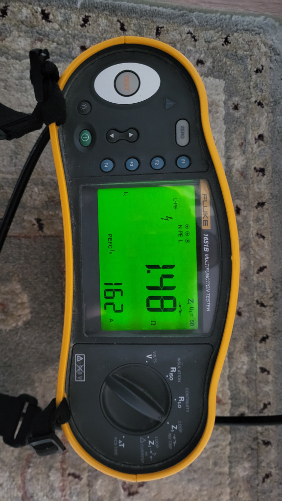
    I have mine operating with an unswitched neutral. My fault loop impedance at the furthest socket when off grid, is well within spec.

    1000021114.jpg


  • Registered Users, Registered Users 2, Paid Member Posts: 8,220 ✭✭✭deezell


    I definitely think that switching is not enabled on our SMs. The N is straight through. There are beefier looking versions of that singular meter with what looks like additional connection hardware, perhaps relays even. The Kamstrup Omnipower RM106 installed in mine is the bare bones I feel. It doesnt have it's own published installer manual, but appears to be a part of similar units such as the one illustrated in the manual I linked. Which is designated as a GB model.

    Though it has the switch symbol and led indication, I'm assuming these are not implemented on the live circuit, and definitely not on the N. As @graememk points out, there doesn't seem to be the space for such necessarily robust switching of one or both feeds. It's an extra complication that wouldn't have arisen in the 2019 thread, which was prior to the SM rollout. Thus the presence of a permanent physical live and looped N connection remains in the new meters as per all the old ones. I'll accept that is the case.

    So, we're back to the argument of breaking this N-E bond with a changeover switch, but having already repeated N-E on the backup source side, so no change really in the virtual circuit, just an isolation of the grid N path back to the permanent N - E bond in the meter box. This leaves just the E wire as the path to there. I'm ok with that.

    Fwiw, any auto changeover switches I've looked at are either 2 pole for L and N, or 4 pole for 3 phase. They need N anyway to power the relays. I'd guess there are plenty of big manual changeover switches on houses, outhouses and farms which consist entirely of a single pole throw switch, with a centre off position, to ensure at least that one source L is broken before the other is made.

    Uninterrupted changeover where the second source is always 'hot', such as an isolated inverter secondary output, or a grid tied hybrid with a configurable off-grid trigger port, (reffered to as D1 or D2 on many models), definitely requires a milliseconds fast changeover, and it behoves intuition if nothing else, to pull both L and N from one source before hitting the other source. Phase syncing is another factor but let's not go there in our thread, and it's not possible in cheap generator backup anyway. These will be cold change over in the first instance, because you have to start it, or wait for autostart if you've a commercial model.

    Automatic changeover back when the grid restores will be fairly flicker free. And better done on both L and N.

    As anyone out there with eectrical/electronic practice under their belt knows, a very short power interruption can be far more problematic than an interruption of minutes. A lot of electronic equipment just doesn't like it, it's akin to a lighting strike for some. It can freeze processors and corrupt operations so you have to power down and cleanly reboot anyway.

    Old style alternator petrol backup generators have horrible noisy waveform anyway, and could benefit from extra line filtering. The waveforms are so poor, they barely resemble a sine wave. A lot of led lights don't like them, nor do some low power switch mode supplies built into devices. My nespresso machine's pressure pump has a nightmare as it tries to regulate current to the pump motor, it coughs and grunts and spits/dribbles out the coffee like it has prostate problems, so if you're thinking generator, pure sine wave models are superior, though fairly expensive for decent size in Kw. Thats enough to chew on for today.


  • Registered Users, Registered Users 2, Paid Member Posts: 8,220 ✭✭✭deezell


    Plus 1 for that if it's allowed. The diagrams for the three phase setup with the unswitched PE neutral show a small link from the generator 6 chassis to the permanently earthed neutral. It's not clear enough to see if its a switch or link which I presume it is at the generator output. PEN is acting as a single conductor for both earth snd neutral generator terminals. There is no separate earth conductor shown, until the distribution to loads, where the PEN is split, with neutral designated conductor going through load breakers etc and the earth designated conductor going without any breaks. It's probably a bit complicated for the pv enthusiasts in single phase land, from whose thread this is a fork. I can't imagine you could just tap the neutral from the meter in the consumer unit and tie it to the earth bus to reestablish an unswitched earth line. Also, if you have a key to those little diagonal terminal symbols it would be great, like this variant for example.

    image.jpg


  • Advertisement
  • Registered Users, Registered Users 2, Paid Member Posts: 1,163 ✭✭✭JohnySwan


    Here you go.

    image.png


Advertisement