Advertisement
If you have a new account but are having problems posting or verifying your account, please email us on hello@boards.ie for help. Thanks :)
Hello all! Please ensure that you are posting a new thread or question in the appropriate forum. The Feedback forum is overwhelmed with questions that are having to be moved elsewhere. If you need help to verify your account contact hello@boards.ie
Help Keep Boards Alive. Support us by going ad free today. See here: https://subscriptions.boards.ie/.
If we do not hit our goal we will be forced to close the site.

Current status: https://keepboardsalive.com/

Annual subs are best for most impact. If you are still undecided on going Ad Free - you can also donate using the Paypal Donate option. All contribution helps. Thank you.
https://www.boards.ie/group/1878-subscribers-forum

Private Group for paid up members of Boards.ie. Join the club.

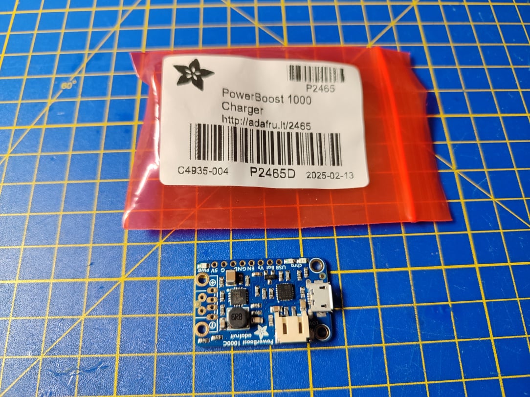
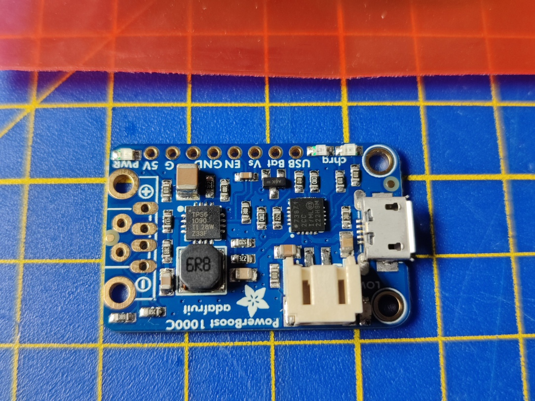
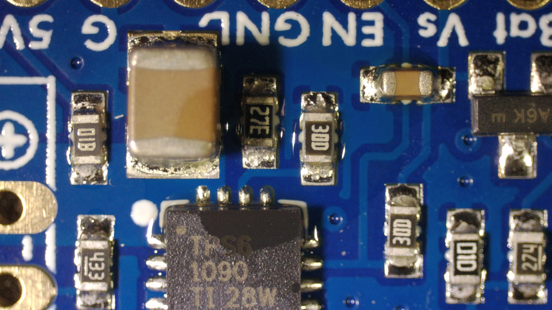
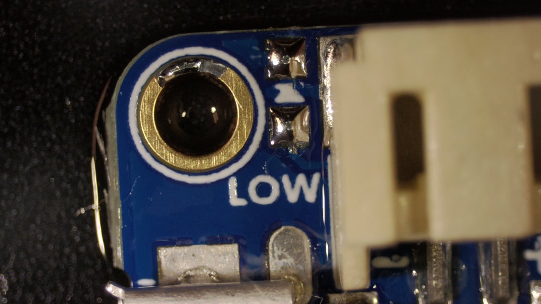
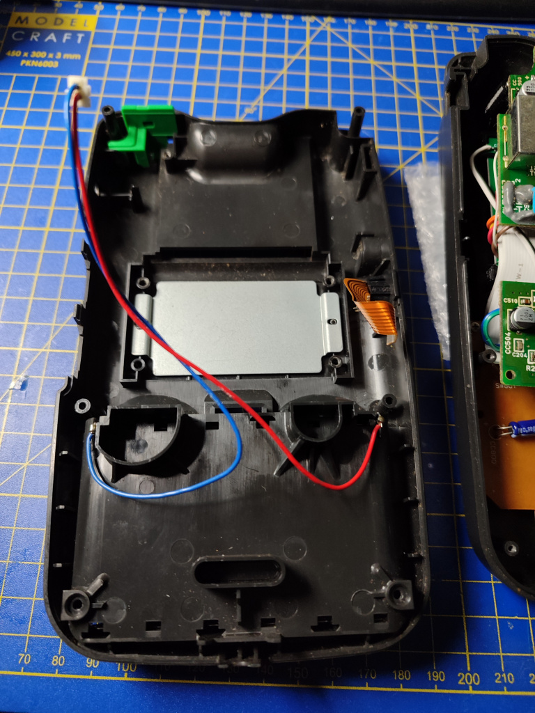
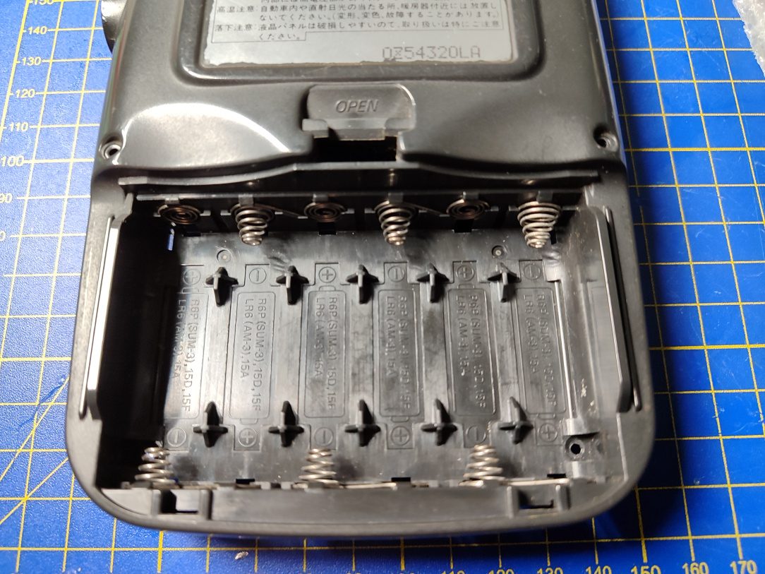
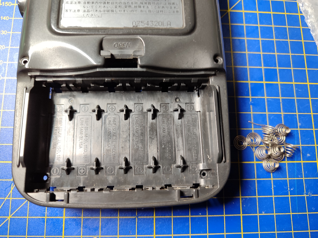
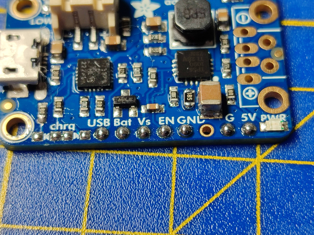
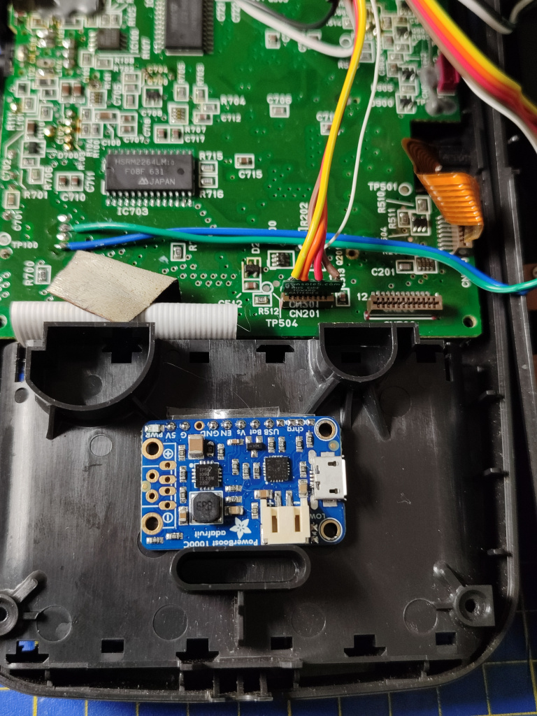
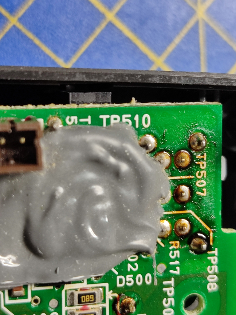
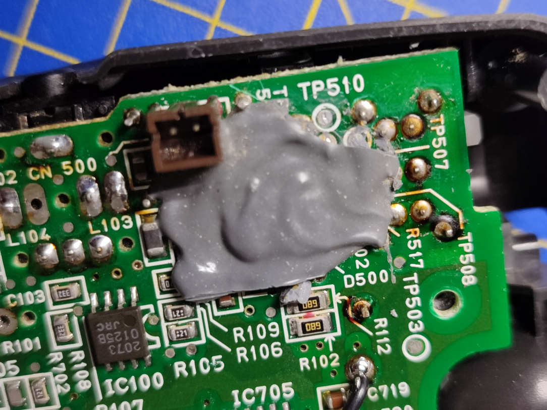
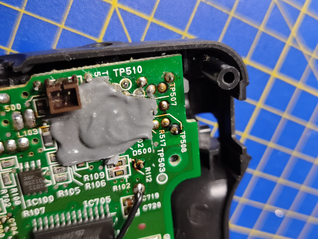
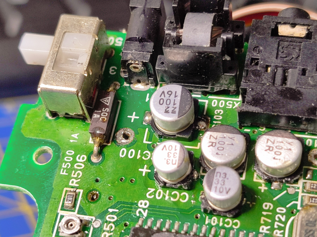
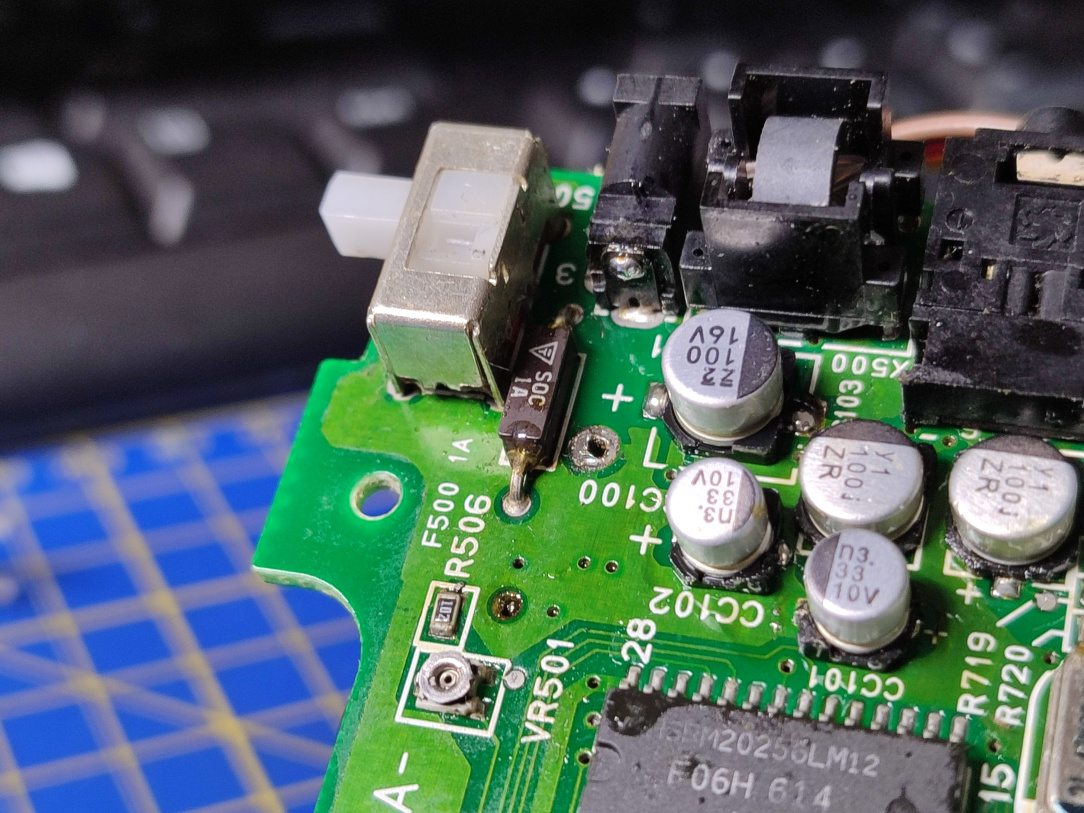
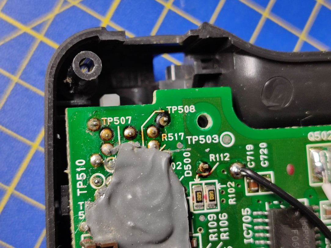
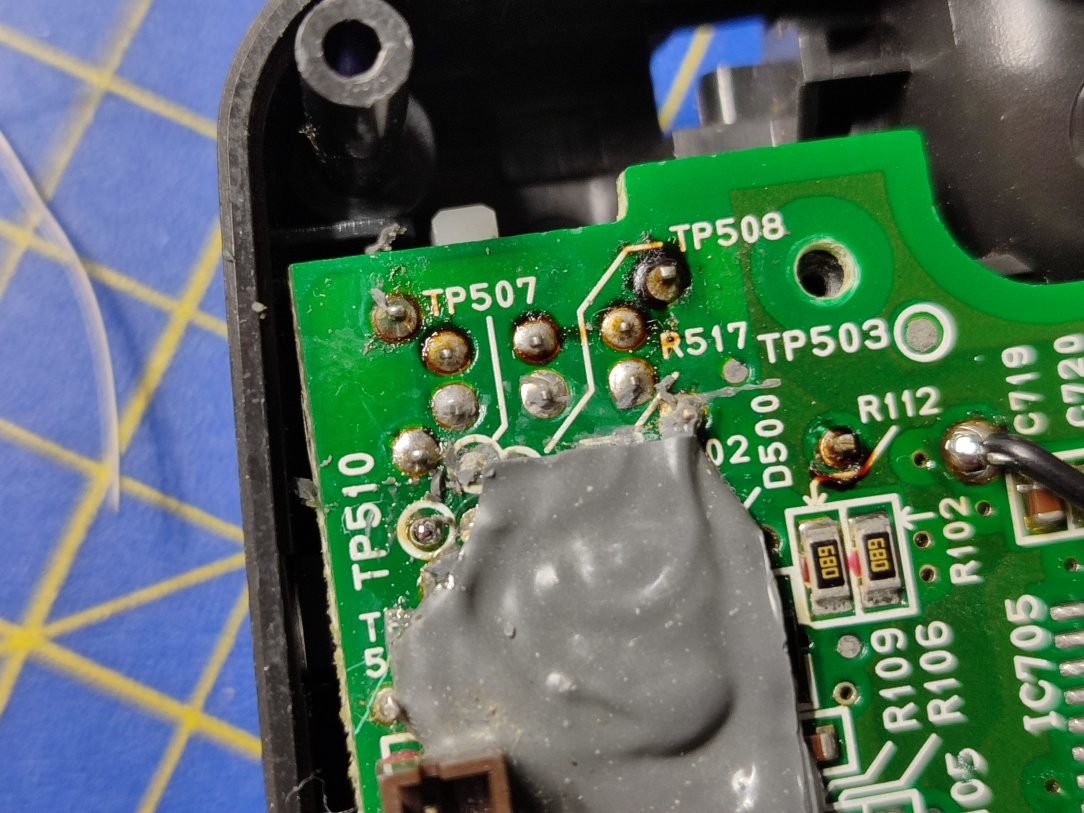
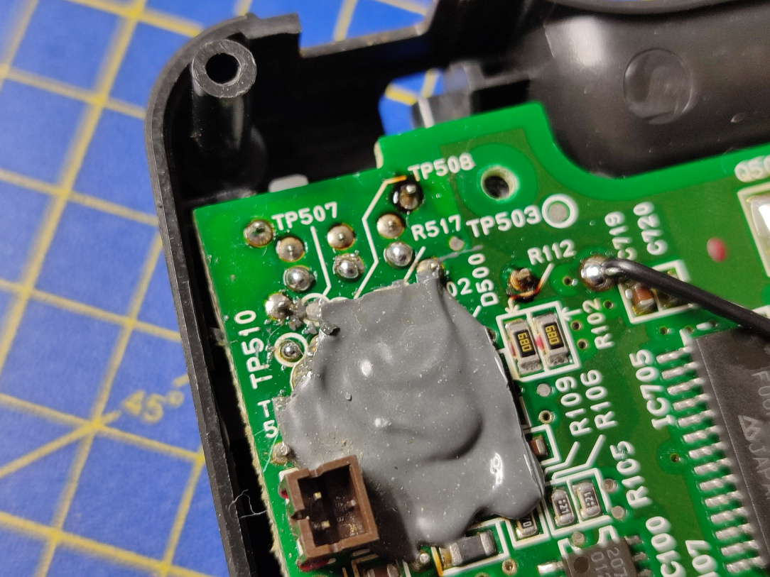
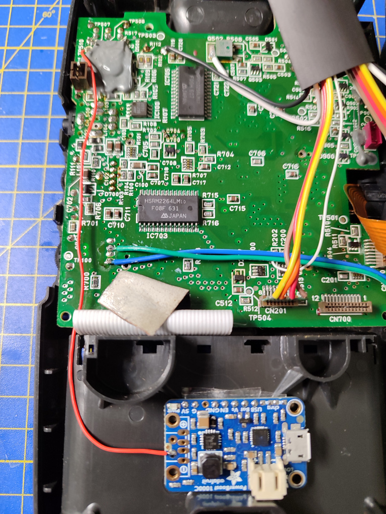
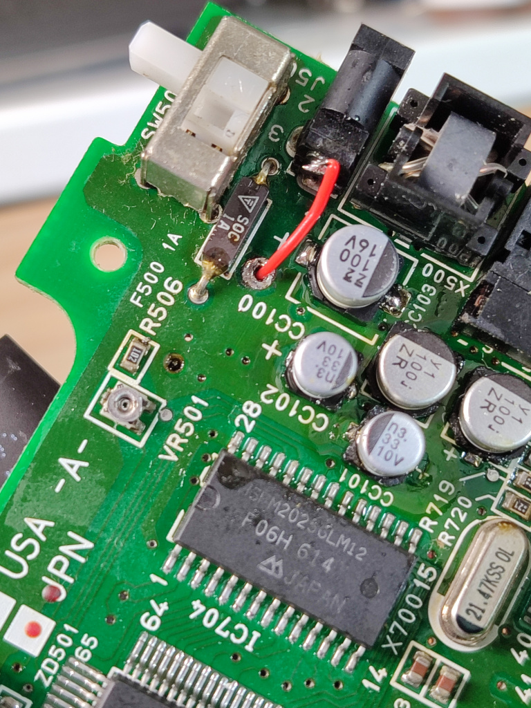
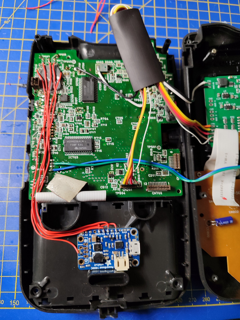
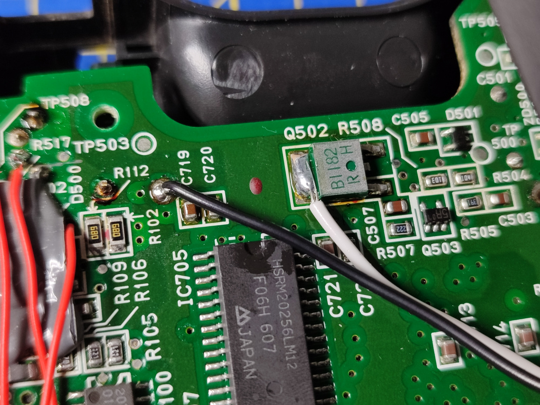
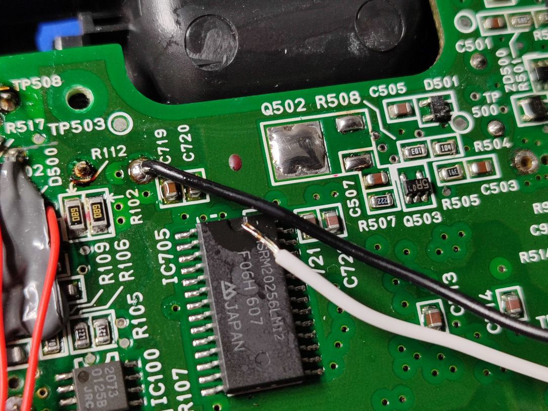
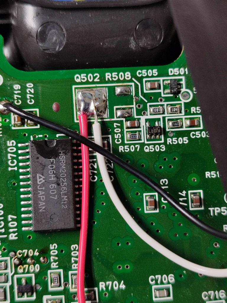
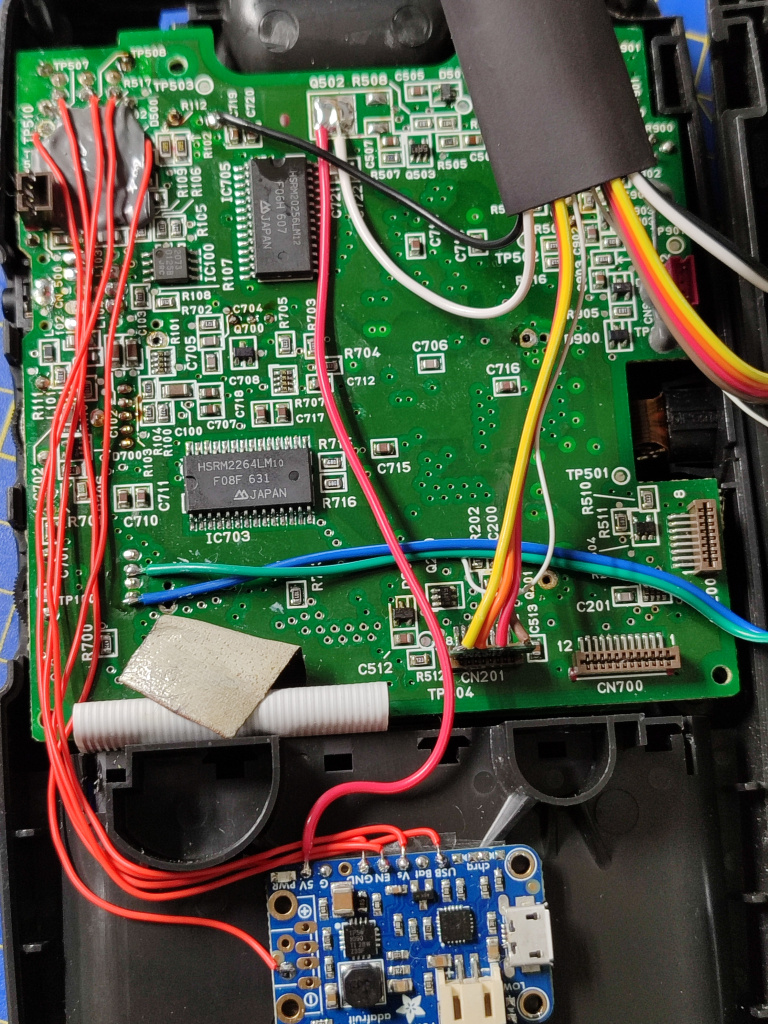
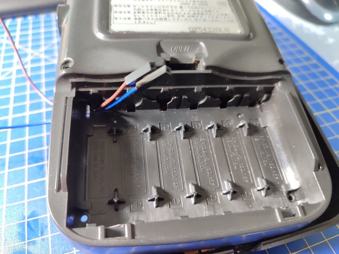
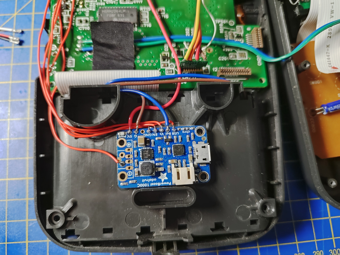
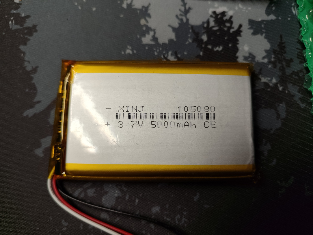
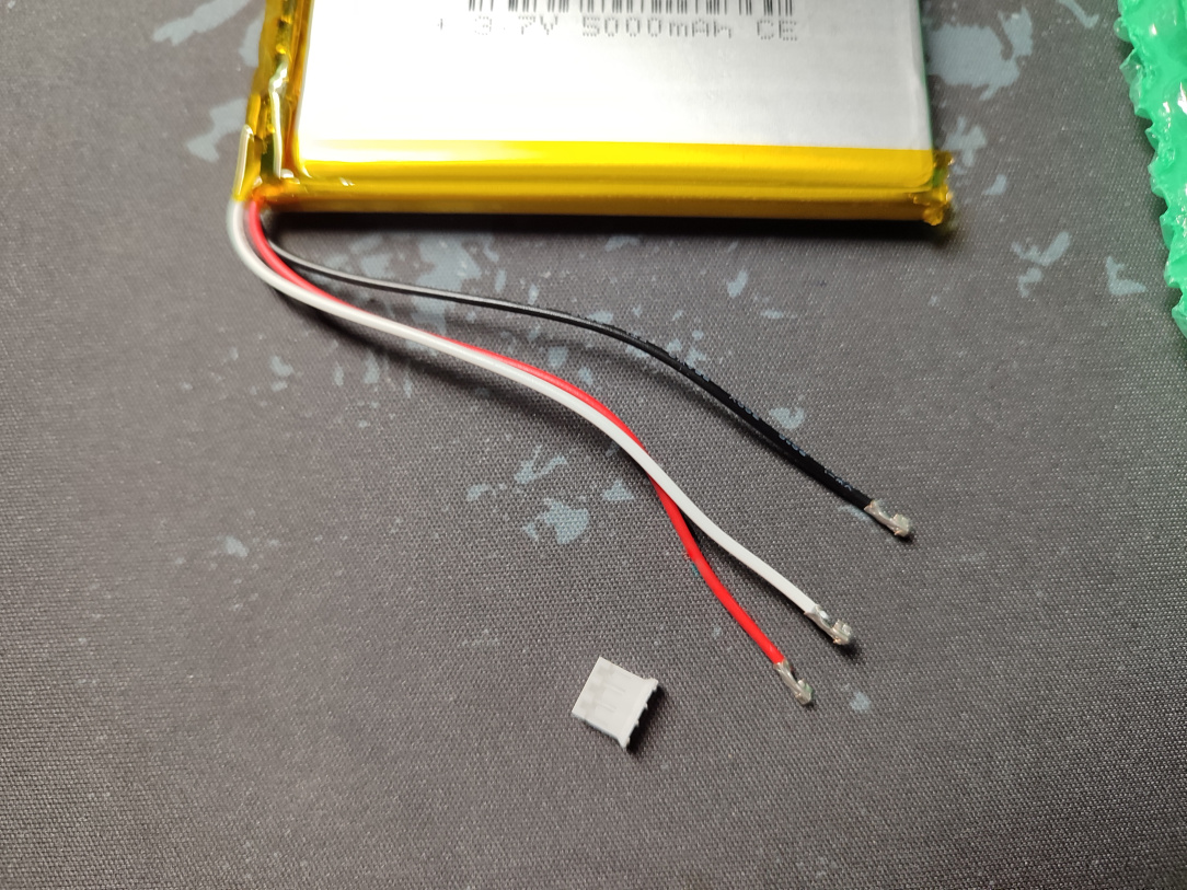
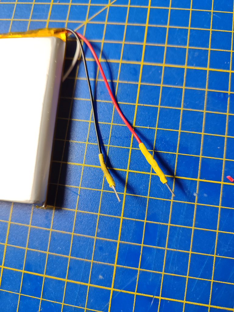
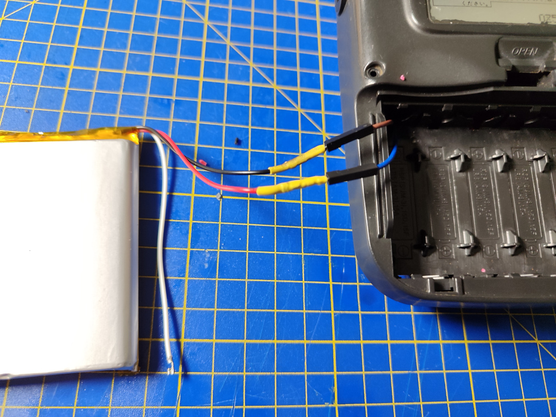
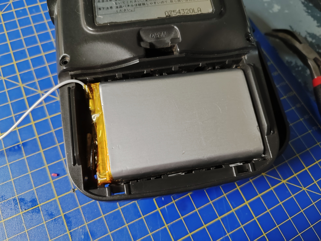
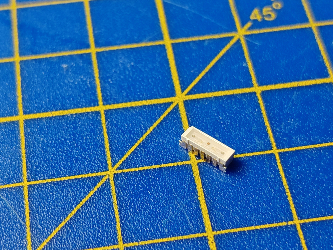
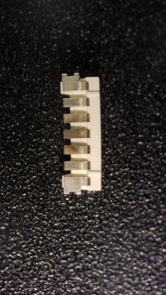
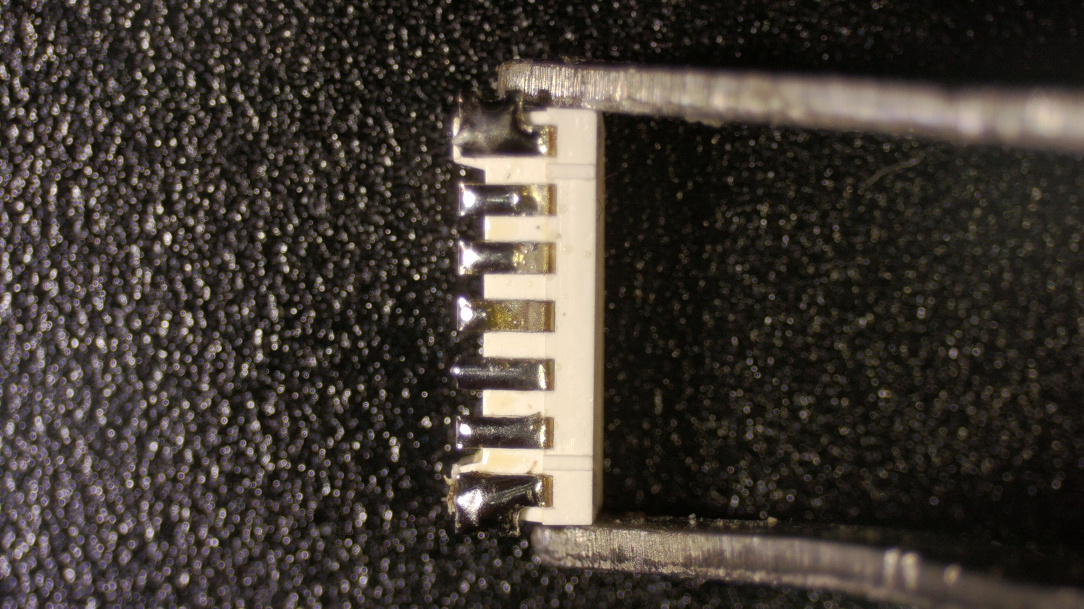
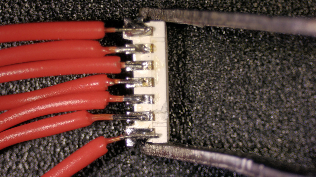
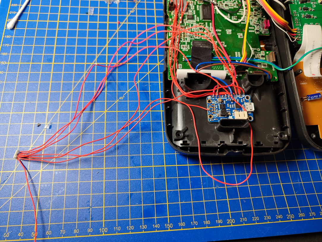
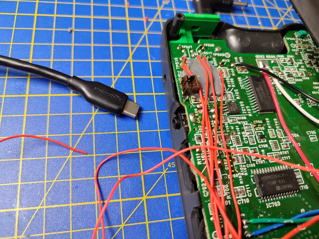
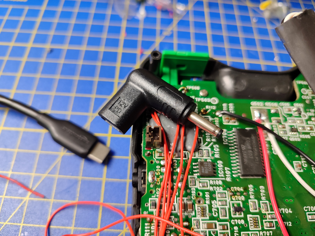
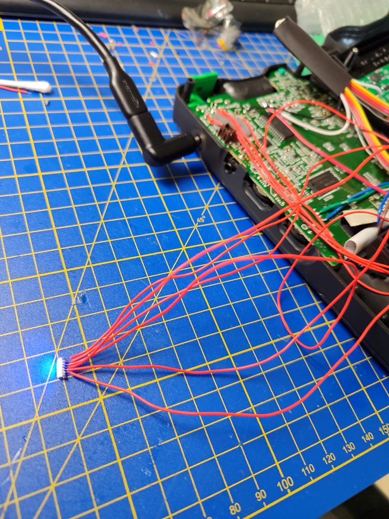
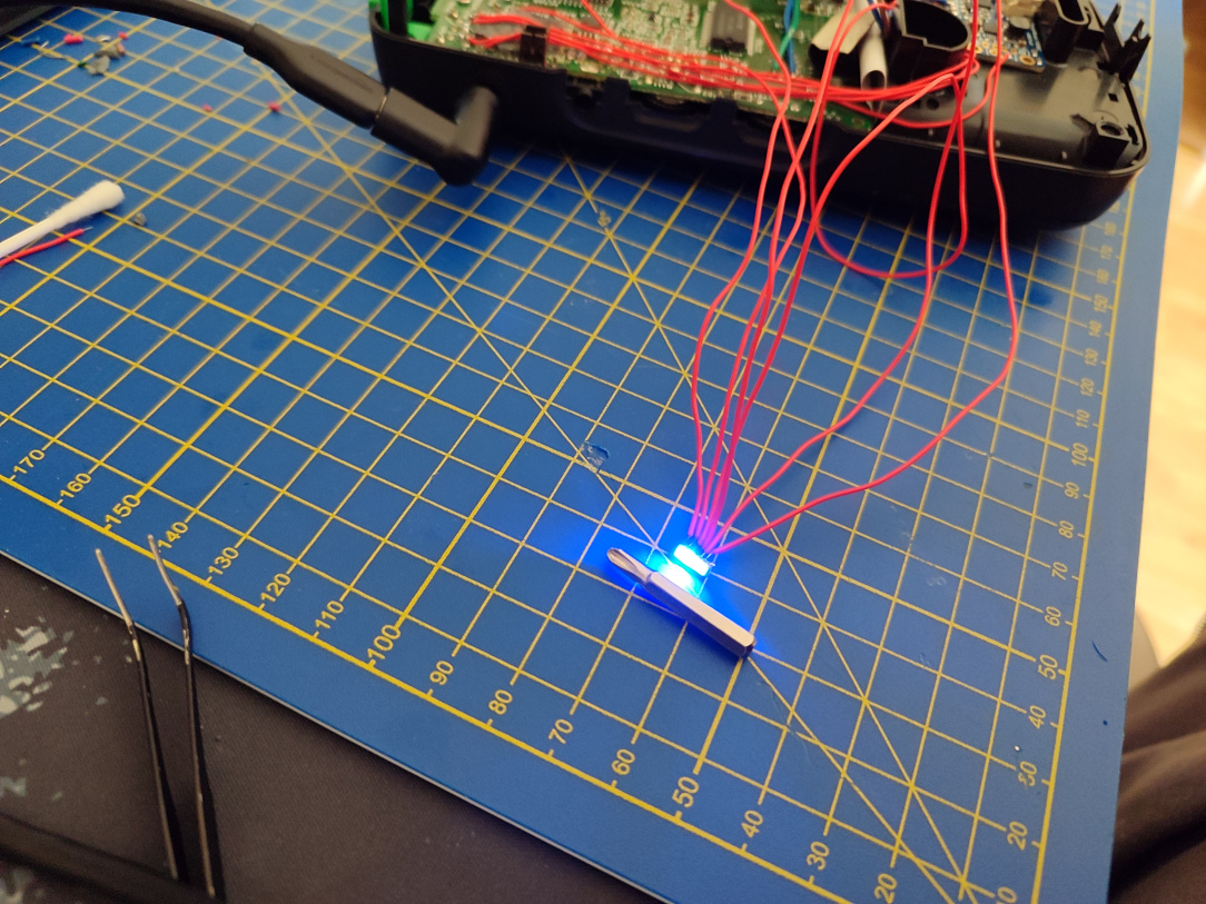
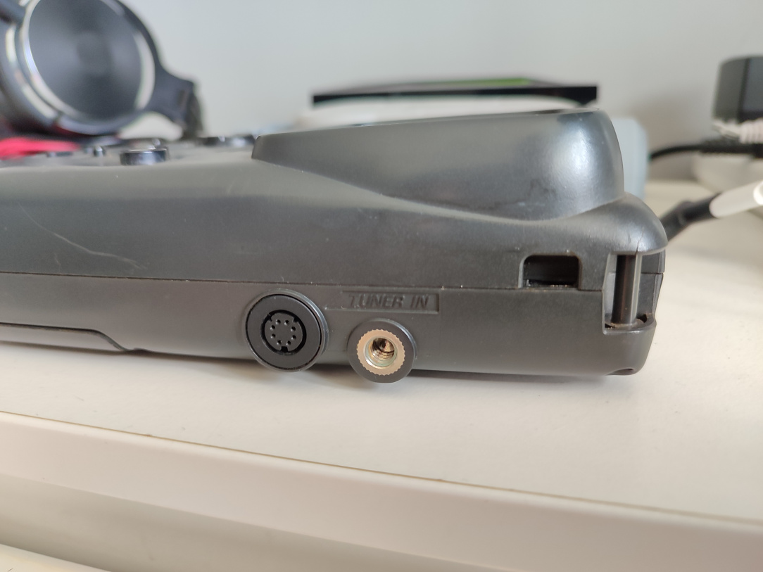
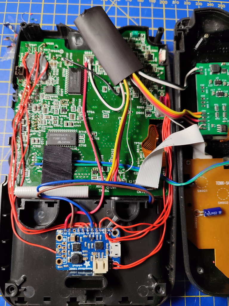
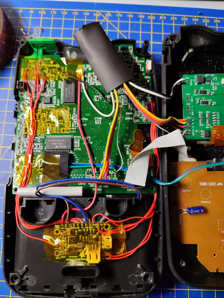
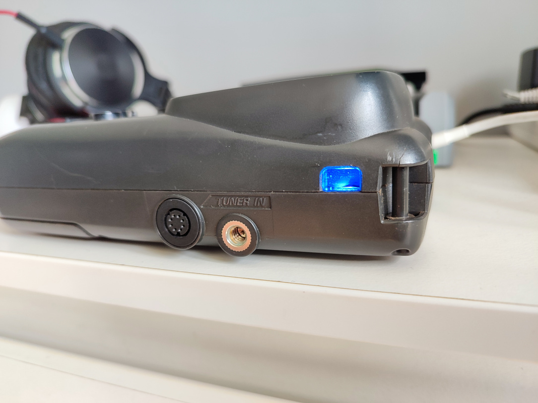
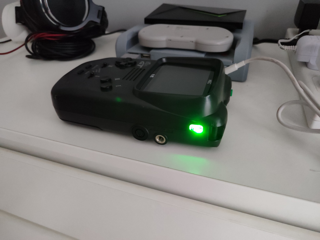
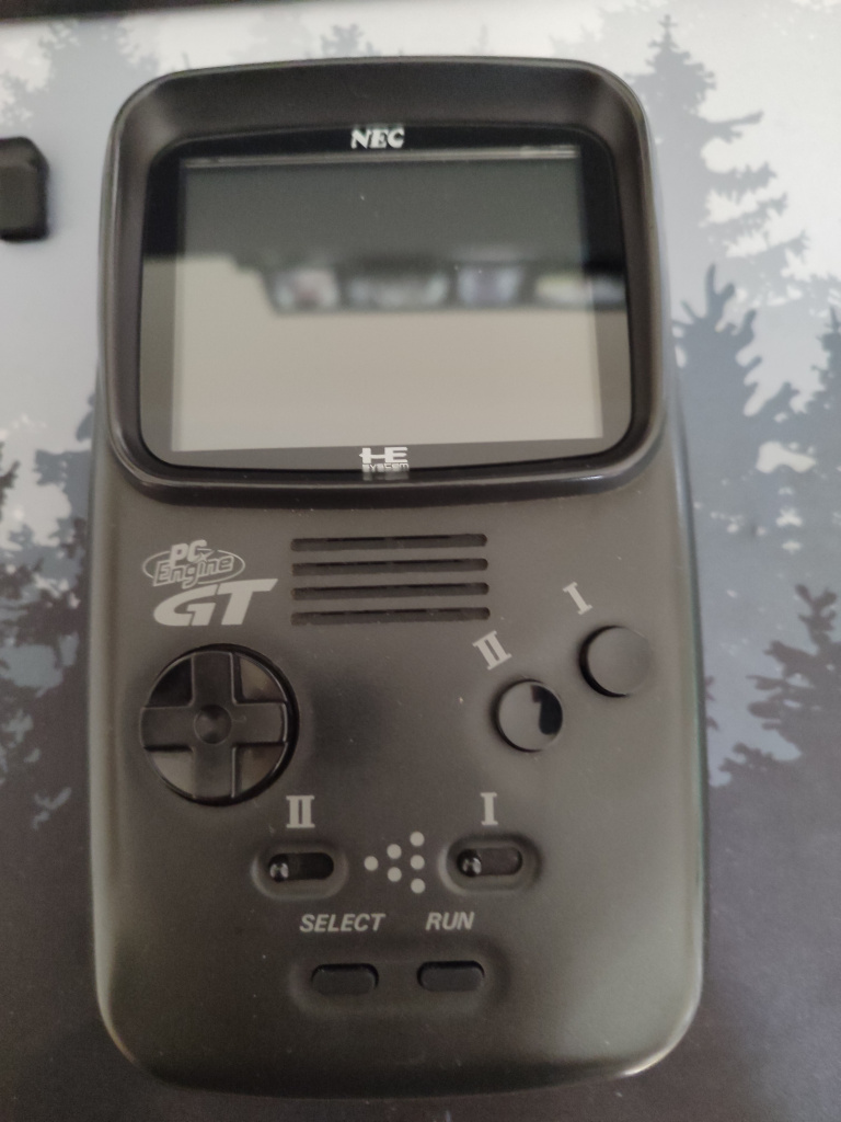
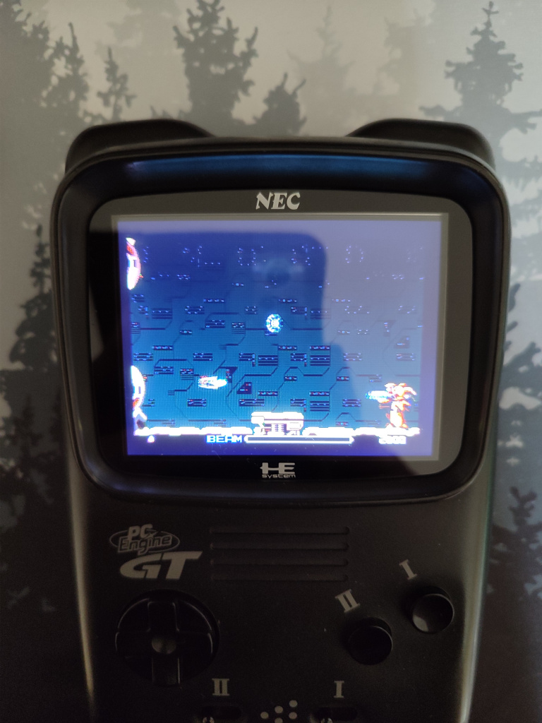
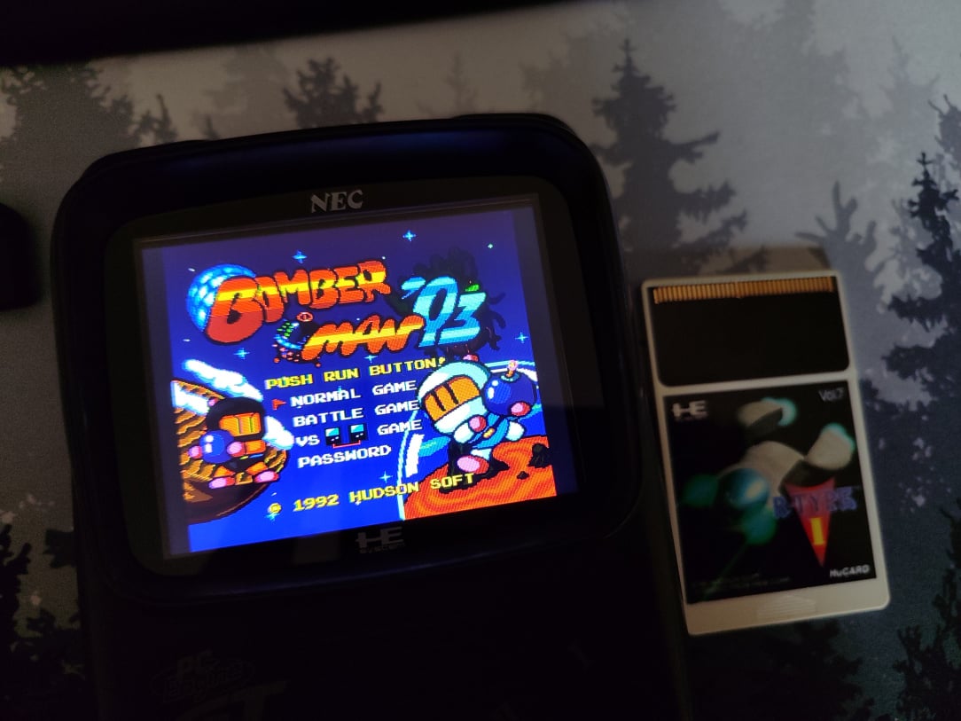
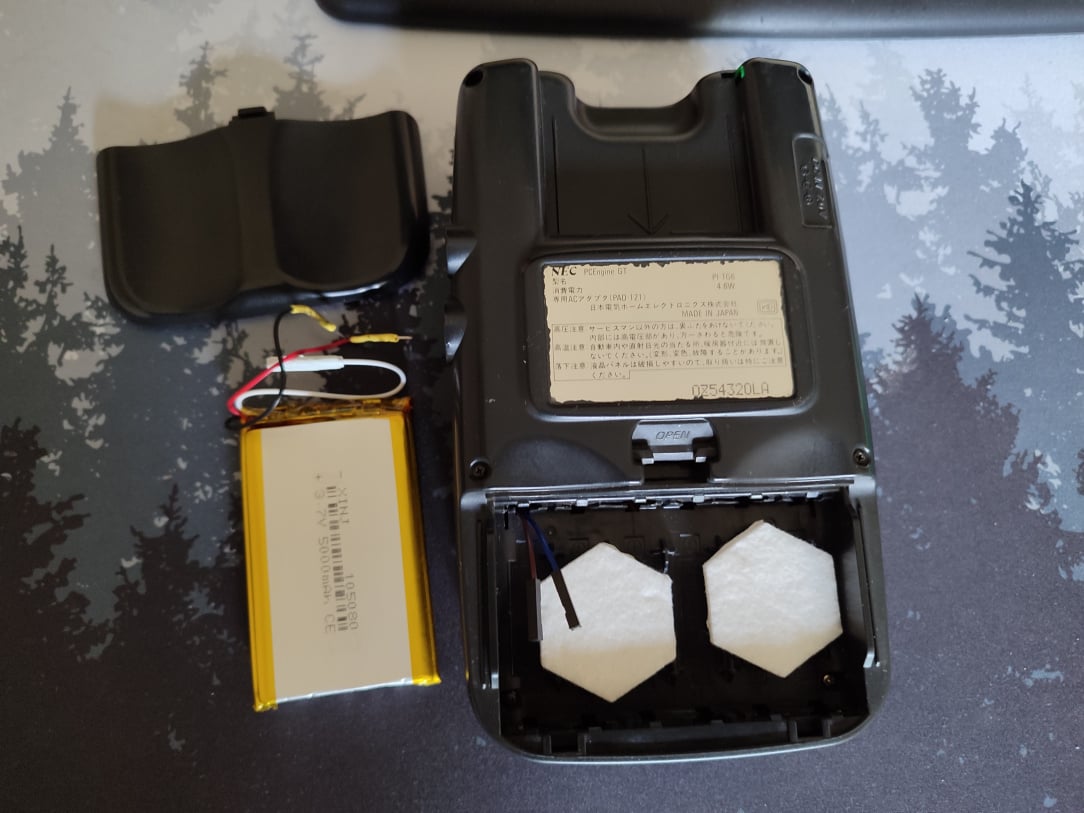
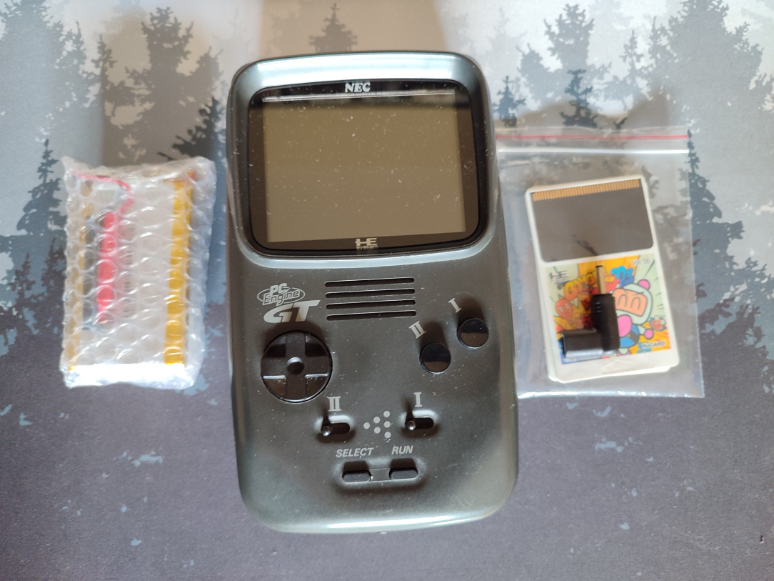
Handheld Hijinx Vol 10A - PC Engine GT Internal Battery Mod

  • 29-07-2025 05:46PM
    #1
    Registered Users, Registered Users 2 Posts: 8,161 ✭✭✭


    My previous thread on this PC Engine was the installation of an LCDDRV Kit, which turned out to be an enormous improvement to the stock screen. The finishing touches really only call for some type of modern way to power/play this handheld, short of sticking to a wired PSU or else using x6 AA batteries all the time. The modern solution is to install a LiPo (Lithium Polymer) rechargeable battery & associated controller to handle everything from now on. There's not a huge amount of documentation on doing this, other than a very helpful thread here (thank you MasterofBiscuits). The OP of that thread kindly drew up a wiring diagram, so all I needed to do myself was figure out the wiring for status LED's, wire routing, and a way to charge it without cutting the shell for a USB slot, etc.

    1753802585791.jpg

    ^^ The first of the few important bits we need for this mod - the Adafruit PowerBoost 1000C. This will manage the charging and power provision from a LiPo battery, to the power circuit of the PC Engine GT. Nice small little device, should fit nicely inside, and seems a perfect fit for the mod.

    1753802585778.jpg

    ^^ A slightly clearer pic. This has all the pins to manage everything, from switching on the PC Engine GT, to charging it, to powering it, to handling LED status lights, etc.

    1753802585767.jpg

    ^^ The first step though is to modify the PowerBoost 1000C slightly, by changing out a resistor on it. By changing this resistor, we configure the power output of the 1000C for 5v, which is what the PC Engine expects. The resistor we need is a 1.8Mohm resistor, to replace the stock 1.9Mohm one. I've a strip of these as shown above.

    20250728_103624.JPG

    ^^ The resistor in question, center of picture (value of 27E). That needs to come out. As you can see though, these are tiny components so I've switched over to the microscope for this bit.

    20250728_104150.JPG

    ^^ Some flux and heat later, and it comes off.

    20250728_104507.JPG

    ^^ I wick the pads clean, and clean with some IPA. We've a nice clean base now for the new resistor.

    20250728_104953.JPG

    ^^ And it's in. A small but important modification.

    20250728_105130.JPG

    ^^ Next I move my attention to the battery status LED's. These illuminate for Charging, Full, and Low Battery. The two shown here are for Charging and Full. They're no good to me on this board though, as it'll be hidden and sealed up inside the console, so I need to remove these LED's, and prep the pads they're on for eventual wiring to an external LED indicator.

    20250728_105401.JPG

    ^^ This is the LED for low battery status.

    20250728_105752.JPG

    ^^ LED's removed, and pads wicked and cleaned. You can see the center two pads for hard-linked.

    20250728_110015.JPG

    ^^ Pads now prepped with fresh solder.

    20250728_105645.JPG 20250728_105905.JPG

    ^^ Same treatment then for the Low Battery pads.

    1753802585757.jpg

    ^^ Now, I've the PC Engine GT stripped apart here ready for working on. I need to remove the battery compartment springs, then have a think about where I want to mount the 1000C and run the wiring etc.

    1753802585747.jpg

    ^^ These are the springs that'll need to come out. Hopefully the battery sits in here nice and snug.

    1753802585736.jpg

    ^^ Done. That gives us a nice bit of extra space, and they're easy enough to remove (and reinstall if ever needed.)

    1753802585728.jpg

    ^^ I then tin all of the pads I need on the 1000C, before it gets fit into the shell. It just makes wiring things up easier, and reduces risk of accidentally hitting anything with the iron later on.

    1753802585617.jpg

    ^^ I'm thinking here, on the back of the battery compartment. I use a small piece of mounting tape to secure it, and by having it here, it's far enough away from the mainboard/screen etc which is a bonus.

    1753802585716.jpg

    ^^ Ok, at this stage we get down to the nitty gritty and start the prep & wiring on the PC Engine GT itself. The ground point we need is the point labelled TP-510. It's slightly covered by this epoxy type grey goop, so we'll need to cut some of that away to fully expose the point itself.

    1753802585704.jpg 1753802585691.jpg

    ^^ Done, cleaned, and tinned for wiring.

    1753802585680.jpg

    ^^ Now, as I mentioned earlier, I want this to be as no-cut as possible, and as such, I don't want to cut the shell for USB ports to power/charge. Instead, I want to use the original DC port, and have that feed power to the 1000C instead of a usb port. To do this, I need to tin the pin at the back of the DC port, and eventually solder a wire to it.

    1753802585668.jpg

    ^^ Back of the DC barrel now tinned.

    1753802585653.jpg

    ^^ Next, we need to expose and solder to three points that are connected to the power switch. These three points will communicate with the 1000C to power it on by providing power to the EN pin (Enable), voltage to the VS pin (Voltage Sense), and a Ground. They're covered again though by this grey epoxy, so we'll cut some more of that away.

    1753802585644.jpg

    ^^ The three points are now nicely exposed…

    1753802585632.jpg

    ^^ Cleaned & tinned, ready for wires!

    1753802585607.jpg

    ^^ First of MANY wires! This is the ground from TP-510, wired to the USB Ground pin on the 1000C.

    1753802585598.jpg

    ^^ We then take a feed from the back of the DC barrel, which will provide power to the 1000C…

    1753802585587.jpg

    ^^ And that's that side done (wires not yet secured.) There's a power supply line from the DC barrel, there's a ground, and the three pins from the power switch, all wired to the 1000C.

    1753802585581.jpg

    ^^ Next step is to remove Q502, as this is where the 1000C board will provide the PC Engine GT with nice clean 5v. It's currently got a white wire going to it here to power the LCDDRV.

    1753802585548.jpg

    ^^ Removed…

    1753802585531.jpg

    ^^ White wire for LCDDRV now restored back to the pad, and along with it, a slightly thicker gauge red wire which will feed everything with 5v from the 1000C.

    1753802585524.jpg

    ^^ That thicker red wire then goes direct to the 5V point on the 1000C.

    1753802585501.jpg

    ^^ Now, one of my wishes for this mod was to have the battery easily removable. I hate leaving any batteries in handhelds etc, and always remove them if they're not going to be used for a prolonged period. I don't have any proper two pin connectors, so I'll temporarily use some dupont connectors to allow installation and removal of the battery without having to open the console every time. I have these two wires, brown will be for - and blue will be for +. They route nicely through the existing holes in the shell too, so no cutting required.

    1753802585484.jpg

    ^^ The two battery wires then get soldered to the 1000C Bat and G points. These will allow the battery to supply power through the 1000C and into the PC Engine GT, and similarly, for the 1000C to feed power back into the battery to recharge it when needed.

    1753802585811.jpg

    ^^ The heart of the operation. A single cell, 3.7v, 5000mAh rechargeable LiPo battery in 105080 size.

    1753802585802.jpg

    ^^ I need to remove the original connector from the battery, as it won't connect to anything we have. The red wire is +, and black wire is -, and the white wire, which we don't need, is for connecting to a thermistor for temperature sensing.

    1753802585471.jpg

    ^^ I fit some male DuPont connectors onto the + & - pins, which will allow us to connect it to the console quickly and easily (though I will likely replace these with proper connections later on.) I also add some heat shrink protection to ensure they don't short out on each other when packed into the battery compartment.

    1753802585461.jpg

    ^^ All connected up!

    1753802585455.jpg

    ^^ And a very lovely fit into the battery compartment it must be said! I'll leave the white wire on the battery rather than cutting it as it tucks nicely into the remaining space (I obviously insulate the pin with some protective tape too, just in case.)

    1753802585445.jpg

    ^^ Ok, the last of the bigger tasks is to wire this tiny SMD LED block, so that we can see at a glance if the unit is charging, full, or indeed about to go flat.

    20250728_122946.JPG

    ^^ Back to the scope again, this thing is absolutely tiny.

    20250728_123418.JPG

    ^^ The pins of the LED are now tinned, and ready for wires.

    20250728_125225.JPG

    ^^ x7 wires now soldered. You only need six, I realised this when looking at the datasheet for how to wire it, so I later removed the top wire. It's extremely fiddly to do this - you need to hold the soldering iron in one hand, solder wire in another hand, and ask you wife to hold the tweezers in place under the microscope so that you can solder it all together (unless you've three arms, in which case you're sorted.)

    1753802585429.jpg

    ^^ Ok we're getting very messy here, but it's only for testing. The idea is, if this works, I'll mount the LED block somewhere, then I'll be able to determine correct wire lengths etc.

    1753802585419.jpg

    ^^ Ok, now, how to plug this USB C lead into the DC Barrel….

    1753802585411.jpg

    ^^ Well with a DC Barrel to USB C adapter of course!

    1753802585400.jpg 1753802585390.jpg

    ^^ Oh sweet, it works. It's showing blue there as the USB is connected, and the 1000C is now charging the battery!

    1753802585251.jpg

    ^^ Now, the big question, where to mount this tiny LED indicator? I refuse to cut the shell, so the place I've settled on is this little notch in the side where the TV Tuner will lock into. Suffice it to say, I won't be ever watching TV on this thing, so this place seems the best fit.

    1753802585377.jpg

    ^^ Ok, you can see the white LED block nestled into the the notch towards the top right corner of the shell. A small internal cut is needed to allow the wires safe passage, but it's internal, I'm ok with that. I've cleaned up the wire lengths now too. The OP of the tutorial I linked to above used magnet wire for this bit, which makes sense - except I don't really like working with magnet wire, it's prone to detaching and given a needed a good connection for wiggling this in and out of position/routing wires etc, I opted for more small gauge wire. I was confident enough it'd all fit, and will allow me a bit more security for moving things around (hats off to that person for doing this with magnet wire, not an easy task!)

    1753802585352.jpg

    ^^ Everything tidied, routed, and secured with kapton tape.

    1753802585240.jpg

    ^^ A nice, glowing indicator that it's charging now. I'm very happy with this as it's not a garish led in your face, it's more of a coloured glow given how low down I was able to mount the SMD LED block to hide it.

    1753802585226.jpg

    ^^ And we're fully charged! The LED will also turn RED if the battery goes low enough too.

    1753802585296.jpg

    ^^ Now, all back together. Will the damned thing work after all that?

    1753802585279.jpg 1753802585265.jpg

    ^^ Yus! It works perfectly, no AA batteries, and no wired PSU!

    1753802585217.jpg

    ^^ I had these IKEA furniture pads spare, so added them into the bottom of the battery compartment as there's sort of spikey plastic there. I'm sure it'd be fine, but just incase the battery got pierced/worn down over time, I've added these pads to cushion everything.

    1753802585199.jpg

    ^^ All done. I make two makeshift sleeves for the battery pins when its in storage as the two pins are exposed. I just sealed one end of some heat shrink sleeve, and slide the pins into the open end. Crude, but effective.

    Donezo!


Advertisement