Advertisement
If you have a new account but are having problems posting or verifying your account, please email us on hello@boards.ie for help. Thanks :)
Hello all! Please ensure that you are posting a new thread or question in the appropriate forum. The Feedback forum is overwhelmed with questions that are having to be moved elsewhere. If you need help to verify your account contact hello@boards.ie
Help Keep Boards Alive. Support us by going ad free today. See here: https://subscriptions.boards.ie/.
If we do not hit our goal we will be forced to close the site.

Current status: https://keepboardsalive.com/

Annual subs are best for most impact. If you are still undecided on going Ad Free - you can also donate using the Paypal Donate option. All contribution helps. Thank you.

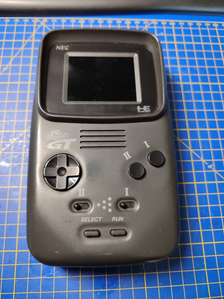
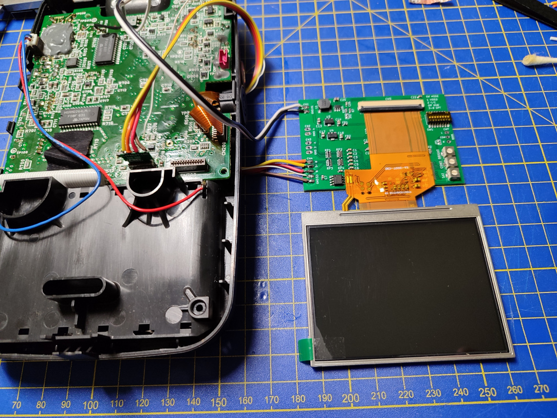
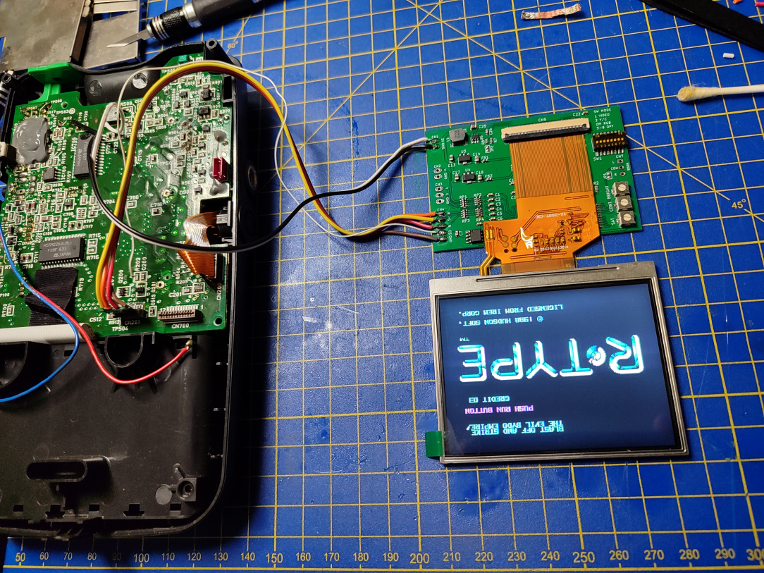
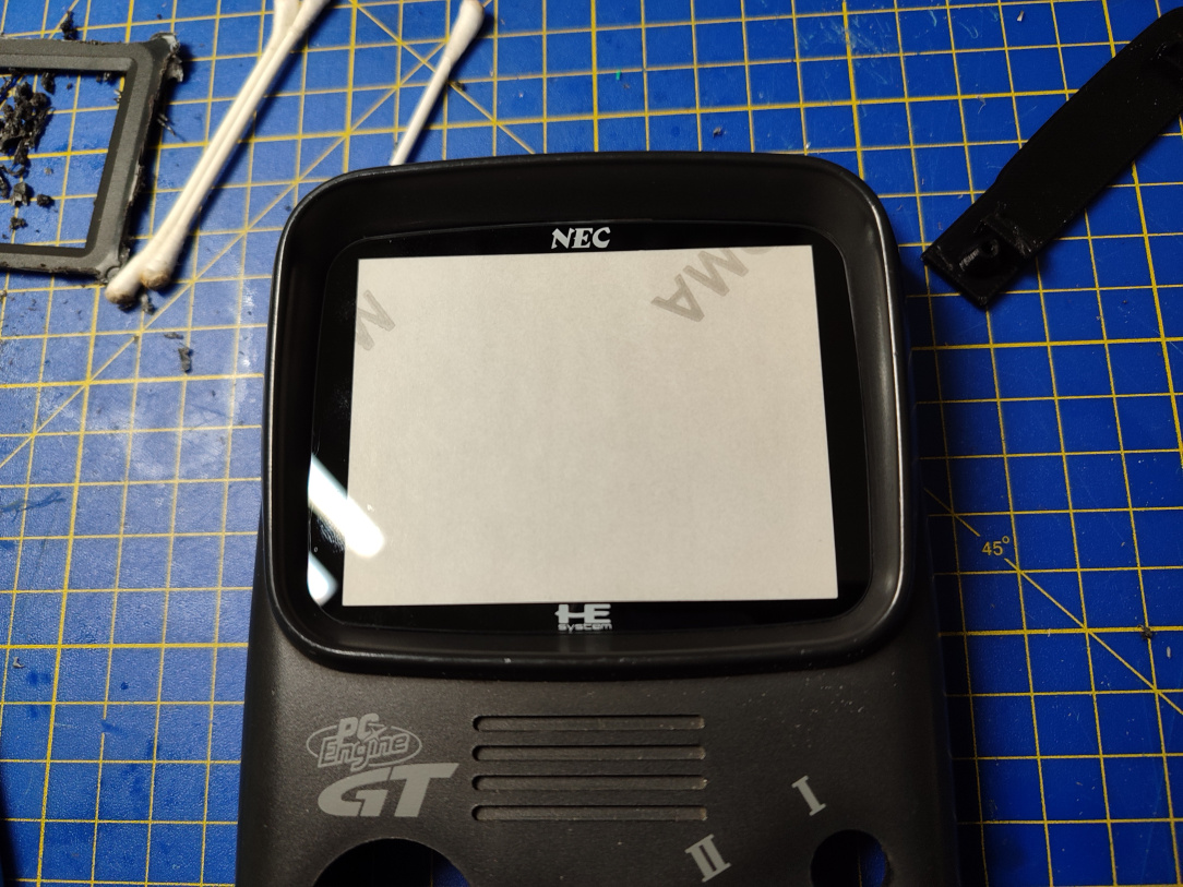
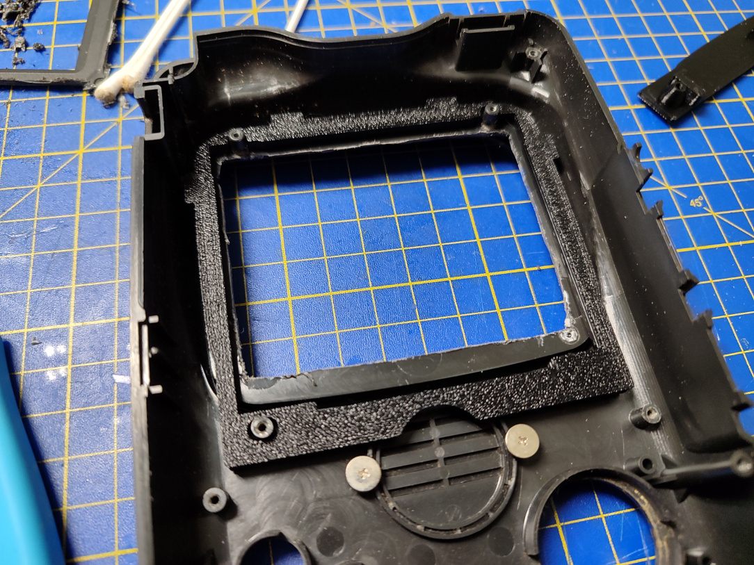
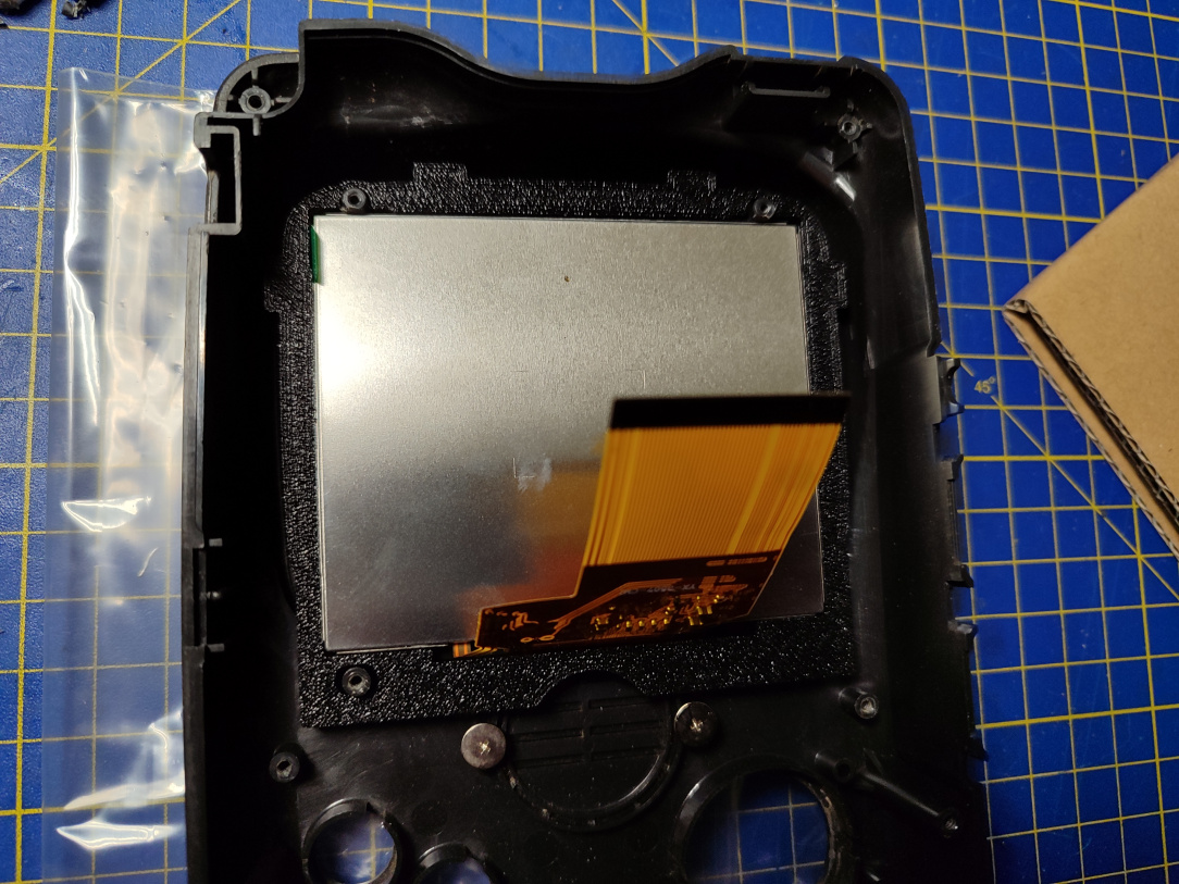
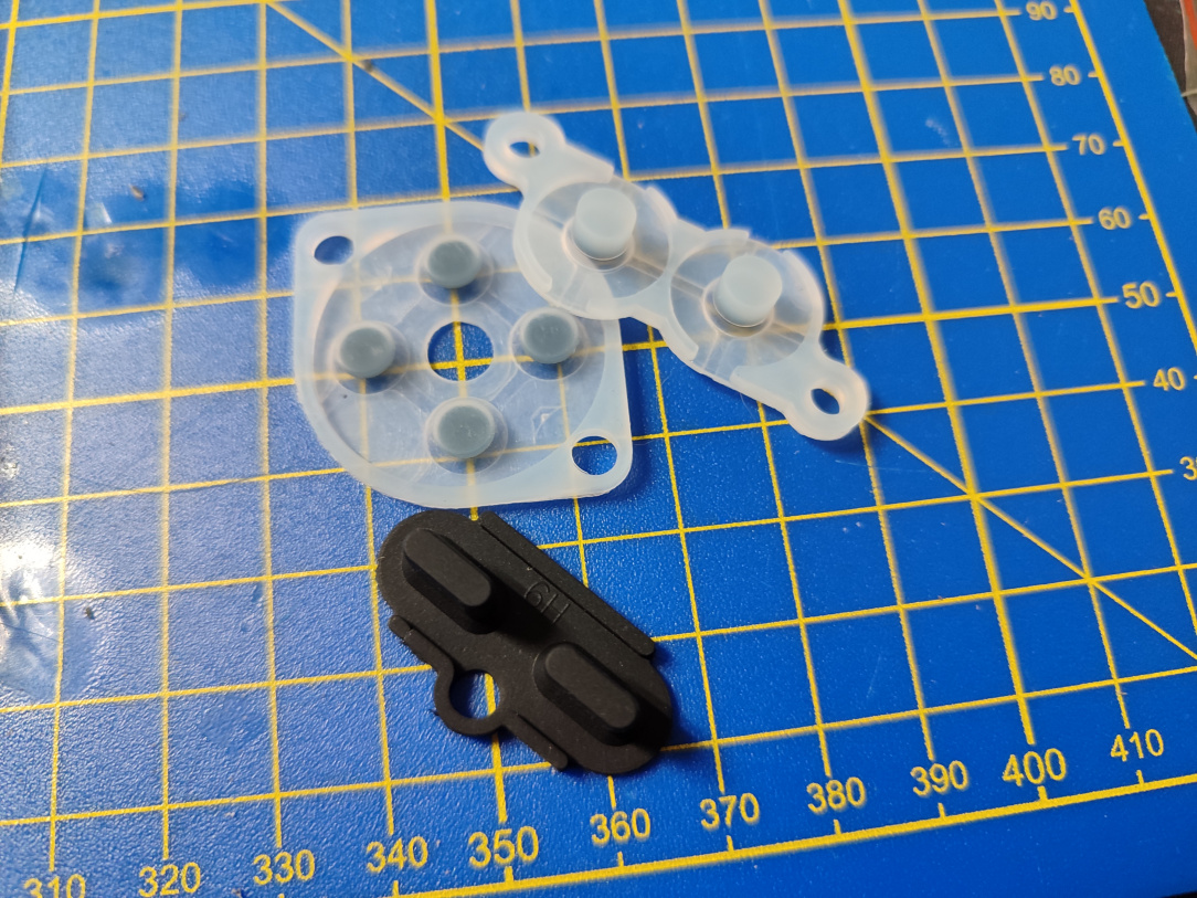
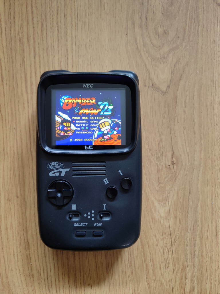
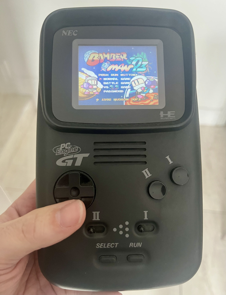
Handheld Hijinx Vol 10 - PC Engine GT (I can see clearly now the grain has gone)...

  • 27-06-2025 03:05PM
    #1
    Registered Users, Registered Users 2 Posts: 8,148 ✭✭✭


    A good while back I got a PC Engine GT off of Quigs (haven't seen you post here much lately man, hope all is well). He had bought it as part of a bundle I believe, and very shortly after, maybe one or two uses, it packed in. I took it, feeling I'd have a good shot at repairing it as it was likely just a capacitor issue (these are known to suffer from cap leakage and bad caps.) I'd recapped one before for Quigs, so I'd a good idea of what was involved in it. Sadly, t'wasn't to be. A full recap, and the screen was still dead. I knew the GT was working, as I could hear game audio, but the screen was just a static white with no signs of life at all.

    At that point, the fault kinda paved the way for me to justify a more drastic type of repair. Usually I much prefer non destructive no-cut mods, but in this case, the ends justify the means. It was time for a modern screen upgrade. The LCDDRV fit the bill on paper, being RGB based as opposed to the older composite mods, and installation of the kit is pretty straight forward (except the really scary bit of cutting the shell.) So I ordered one up, it arrived, months pass, and while I'm waiting for delivery of some other parts for other projects, I said today's the day….its LCDDRVDAY!

    1751027857770.jpg

    ^^ Behold, the wonders of the PC Engine GT. I love the original PC Engine, it's an amazing, tiny little machine that packs a serious punch. Then they go and make an even smaller, handheld version of it!

    1751027857759.jpg

    ^^ Cracked open, and separated.

    1751027857746.jpg

    ^^ This is a lovely little breakout board from Console5, it gives you large pads to solder the RGB & Ground signals to, instead of the much smaller pins on the ribbon cable connector.

    1751027857731.jpg

    ^^ RGB & Ground soldered up to the breakout board, and simply then plugged in.

    1751027857720.jpg

    ^^ This little via is where we pull the Sync signal from. It's covered in solder-resist though, so will need to be scraped off carefully. It's also on the opposite side of the board to the rest of the wiring, so I think I'll use some 30 gauge wire, pass it through the via, solder it to the pad, and then the wire will be on the topside with the rest of the new wires.

    1751027857711.jpg

    ^^ Via scraped clean, to expose copper.

    1751027857698.jpg

    ^^ I pass the smaller gauge wire through the opposite side of the via….

    1751027857690.jpg

    ^^ …and out it pops.

    1751027857678.jpg

    ^^ Fluxed, soldered, snipped, and cleaned!

    1751027857668.jpg

    ^^ Next up we need to remove the Q507 transistor, and bridge two of its pads. It's an easy removal, tiny pins, so a blob of solder loosens it very quickly.

    1751027857659.jpg

    ^^ Removed, wicked clean, and IPA cleaned.

    1751027857645.jpg

    ^^ Wire bridge then in place.

    1751027857632.jpg

    ^^ These two points then give us out 5v and ground for the LCDDRV board, nice easy points to solder to. The 5v point needed the heat turned up a bit, given it's a much bigger area to heat than the usual pad etc.

    1751027857616.jpg

    ^^ The LCDDRV driver board itself. We need to feed it out new wires, RGB, Sync, 5v, & Ground.

    1751027857604.jpg

    ^^ First though, I disable the original backlight circuit. This removes the more dangerous higher voltages that used to drive the old screen, and supposedly increases battery life as a result. All that's needed here is to remove the solder bridge.

    1751027857591.jpg

    ^^ Done, wicked clean, and IPA cleaned afterwards.

    1751027857578.jpg

    ^^ The moment of truth then. All required wires are now in place, messy, but in place. RGB, Sync, and two Grounds. I feed the batteries in, insert a HuCard….switch the GT on, and…

    1751027857566.jpg

    ^^ Yus! It works, chuffed with that. There was always the doubt that it wasn't the original screen that was faulty, and something else wrong with the image processing side of things. It's very difficult to capture nicely with a phone, but the screen is really lovely, sharp, punchy colours, no more motion blur, and is leagues better than the original one in every objective way.

    1751027857548.jpg

    ^^ So we can extend on the basic wiring install, by bringing the brightness control from the original wheel to the LCDDRV. We solder onto these two pads on the back of the brightness wheel.

    1751027857541.jpg

    ^^ Like so. We then bring those two wires up to the LCDDRV board…

    1751027857532.jpg

    ^^ …and they wired accordingly.

    1751027857506.jpg

    ^^ The JP1 jumper then needs to be solder bridged, and that's all there is to it!

    1751027857514.jpg

    ^^ And I lower the brightness potentiometer down to about 25%, rather than a much higher stock setting. The reason is, with the brightness wheel now in control, we don't want to over-drive the brightness and wash the image out. This way, max brightness on the wheel is what should look like max brightness on the screen, and nothing over it.

    1751027857495.jpg

    ^^ Ugh, the moment I've been dreading. Time to remove the original screen, and….shudder….cut the shell….

    1751027857472.jpg

    ^^ Top shell now emptied out, and ready for work. That original screen is a unit of a thing.

    1751027857464.jpg

    ^^ A bit of fanangling, and the original screen plastic pushes out.

    1751027857449.jpg

    ^^ I clean the area that was under the old screen plastic, as there's old adhesive on it.

    1751027857440.jpg

    ^^ Ok, from here, there's a gore warning. The first post here has been flush cut, as it has to be removed.

    1751027857433.jpg

    ^^ Hmm, I'm still really apprehensive about doing this. One slip of this Dremel and the shell is effectively ruined. You can do this a more manual way, with a side cutter, but I'd be more confident of a straight line is using the Dremel. A hybrid approach of Dremel cutting and flush cutters might work out best.

    1751027857427.jpg 1751027857421.jpg

    ^^ The two top posts you have to put a notch in them, to allow the screen to sit flush. It sort of sits down into this notch, and stays flat and secure.

    1751027857402.jpg

    ^^ This template makes the job a lot less stressful, from Console5 also (the entire LCDDRV Mounting Kit except for the screen/driver came from Console5.)

    1751027857397.jpg

    ^^ You put the template down in place, and draw the lines with a sharpie. Now we can clearly see where to cut.

    1751027857391.jpg

    ^^ Jesus, no going back now. I have the shell clamped in a PCB holder here, as the Dremel would just kick it along the desk otherwise. My idea here was to score the lines a few times, eventually cutting down through them, and going as close as I dare to the corners.

    1751027857384.jpg

    ^^ Ok, cuts made. Rough, and in need of tidying up though.

    1751027857369.jpg

    ^^ Ok, much better. The bottom left corner of the new screen area needed trimming afterwards, I just used a scalpel blade to slide along the plane where I made the cut.

    1751027857361.jpg

    ^^ Brand new PC Engine GT glass insert, this will, if it fits right, look really well.

    1751027857332.jpg

    ^^ Man, it looks gorgeous.

    1751027857348.jpg

    ^^ Screen panel mount now in place, it just drops in over the bottom post, and hugs around the top two posts.

    1751027857320.jpg

    ^^ Screen slots in place beautifully with this mount. You can kinda see where it sits under the notches in the top two posts.

    1751027857306.jpg

    ^^ As part of the refurb, some new control silicon rubbers.

    1751027857290.jpg

    ^^ Ah, the controller one must be for a PC Engine controller, as it's different. Not to worry, the original one works fine.

    1751027857276.jpg

    ^^ The driver board then sits very snugly into the back of the screen mount, and then the whole thing is screwed down into the shell.

    1751027857261.jpg

    ^^ All back together, time to see what it really looks like in its final form!

    1751027857216.jpg 1751027857208.jpg

    ^^ It's really, really, gorgeous. Hard to capture on camera, but I'm absolutely delighted with it. Not only is it fully working again, but, dare I say it, looks WAY better than an original one too. Ok so it's not a no-cut mod, but who the hell would ever go back to using an original screen after using one of these?!

    Peace Out!


Comments

Advertisement