Advertisement
If you have a new account but are having problems posting or verifying your account, please email us on hello@boards.ie for help. Thanks :)
Hello all! Please ensure that you are posting a new thread or question in the appropriate forum. The Feedback forum is overwhelmed with questions that are having to be moved elsewhere. If you need help to verify your account contact hello@boards.ie

Solar PV battery options

Options
12021232526119

Comments

  • Registered Users Posts: 6,064 ✭✭✭championc


    DrPhilG wrote: »
    Yeah I'll do 2 shelves, one above the other and just cable 1 set to the other.

    Neater unit too. My plan in winter is to add sheets of insulation around the batteries and maybe a thermostat controlled fan in the odd chance it gets too warm.

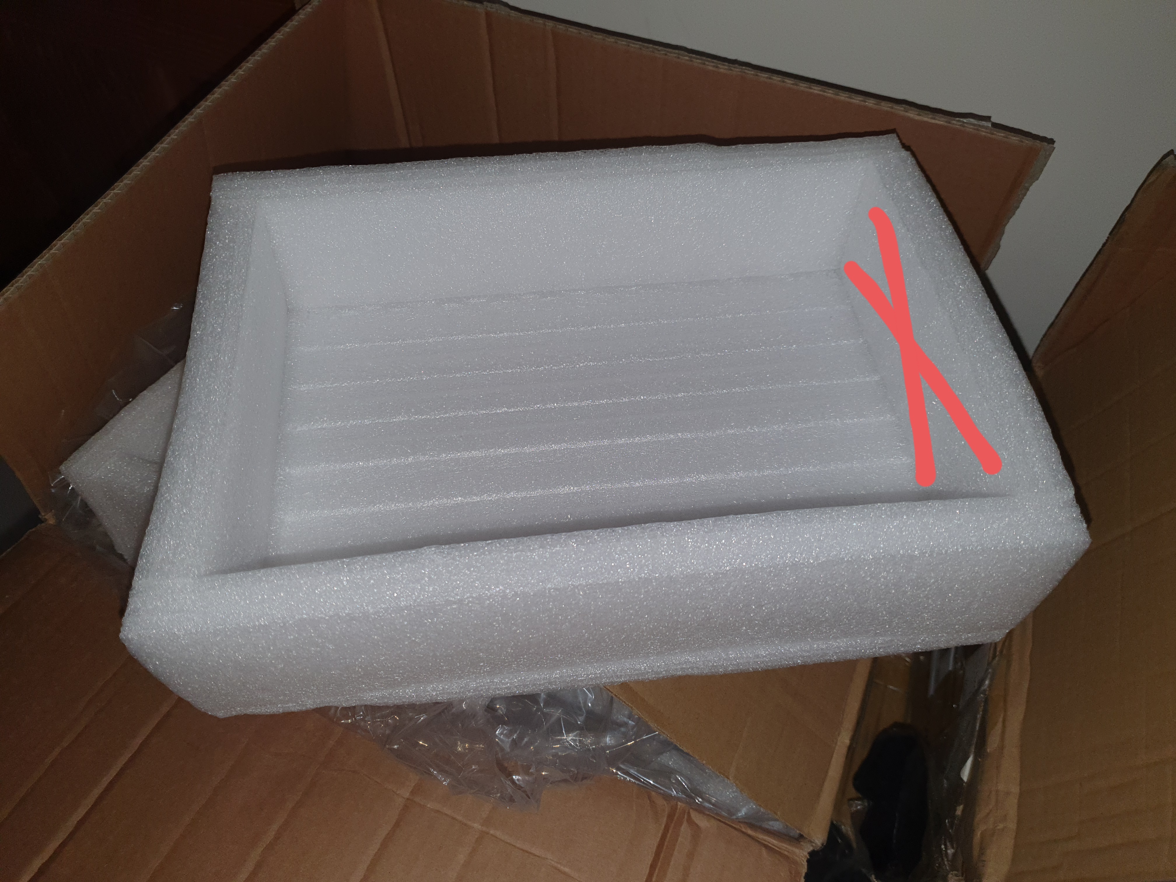
    You should possibly just use the packaging - which I stupidly threw out :(


  • Registered Users Posts: 12,199 ✭✭✭✭DrPhilG


    championc wrote: »
    You should possibly just use the packaging - which I stupidly threw out :(

    Lol, I was thinking just that earlier. Cut these end pieces out and stick some together, it would make a nice base to set them in.

    557468.jpg

    Or would that keep them too warm in summer when the attic is toasty?

    I think some of the thick foam panels built around the frame of the shelves will be fine, easy to take off and on.


  • Registered Users Posts: 12,199 ✭✭✭✭DrPhilG


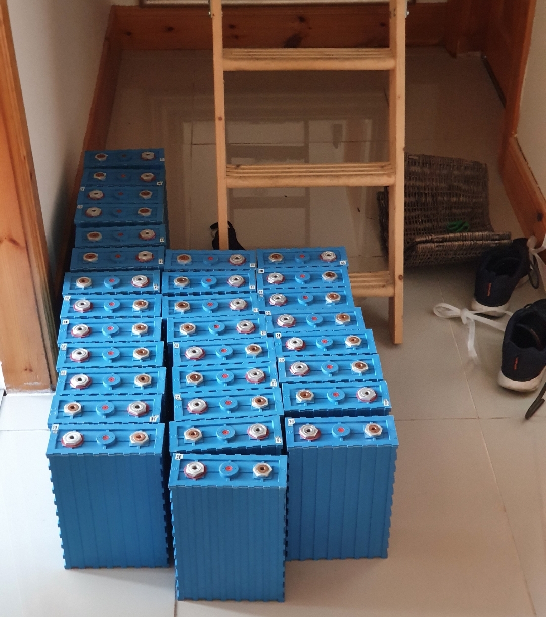
    Wrapped up for the day. 180kg of batteries lugged from the garage to the house and up into the attic is enough exercise for a Saturday afternoon.

    Had some stuff to move around in the attic, and built the shelving unit. Doubled up on the wooden shelf base for extra stability.

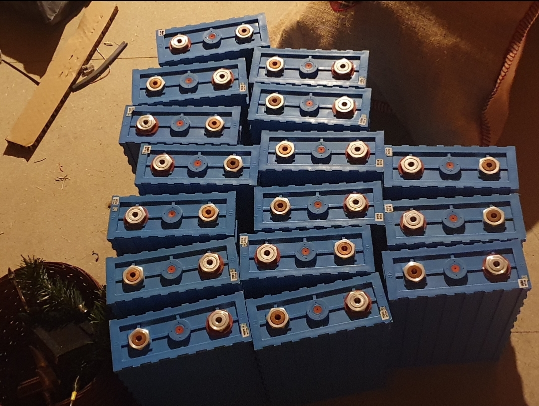
    Pics of the progress so far, and the various bits and bins. That multimeter arrived today also, haven't opened it yet.

    If you're bored enough to count, there's 30 here. 2 already in the attic.
    557469.jpg

    First 16 in place, connections are a job for another day.
    557471.jpg

    Accessories
    557472.jpg

    Leftovers, will go on the middle shelf eventually.
    557473.jpg


  • Moderators, Sports Moderators Posts: 18,698 Mod ✭✭✭✭slave1


    Good stuff, appreciate the pictures of our little project

    My stuff for sale on Adverts inc. outdoor furniture, roof box and EDDI

    My Active Ads (adverts.ie)


  • Registered Users Posts: 6,064 ✭✭✭championc


    The pics (and my pics too previously) don't really give a good impression of the actual size of the cells and bolts


  • Advertisement
  • Moderators, Home & Garden Moderators Posts: 5,798 Mod ✭✭✭✭graememk


    Time to start making up the balance leads, Bit like knitting in front of the tv :P


  • Registered Users Posts: 12,199 ✭✭✭✭DrPhilG


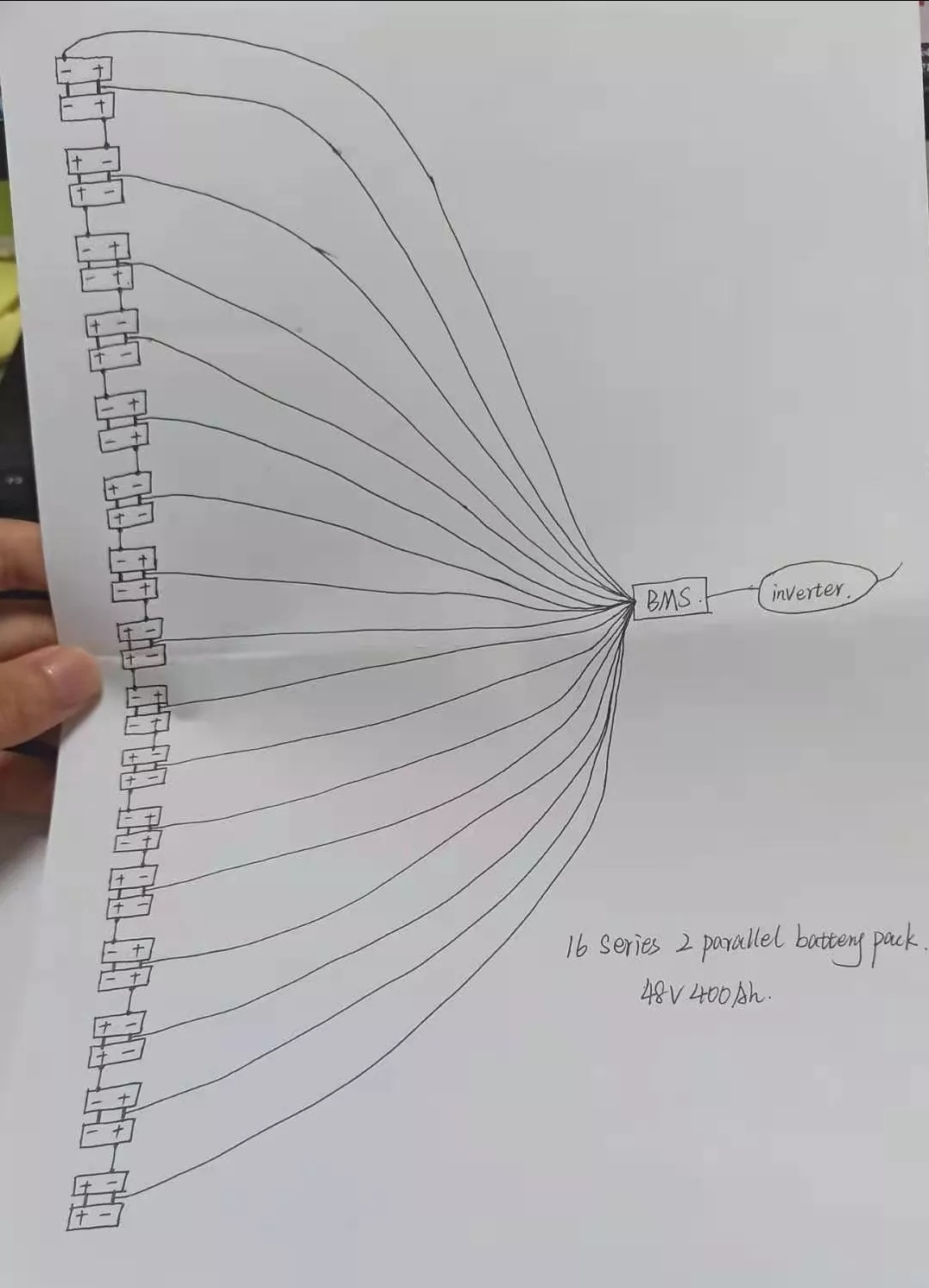
    This was the diagram that I had previously, think it was the battery seller who sent it to me.

    [IMG][/img]


  • Registered Users Posts: 12,199 ✭✭✭✭DrPhilG


    This was the diagram that I had previously, think it was the battery seller who sent it to me.

    [IMG][/img]


  • Registered Users Posts: 12,199 ✭✭✭✭DrPhilG


    This was the diagram that I had previously, think it was the battery seller who sent it to me.

    557484.jpg


  • Registered Users Posts: 64,789 ✭✭✭✭unkel


    Yeah and previously I said a few times that it's better to have them in two 16S1P packs rather than one 16S2P pack ;)


  • Advertisement
  • Registered Users Posts: 6,064 ✭✭✭championc


    So take your time on this.

    IMPORTANT : Connect leads to the battery cells first. Only connect to the BMS after you have tested them ALL

    First of all, the negative lead (or maybe the zero or other colour) goes to the NEGATIVE terminal on the end of the string - this is the terminal which will have a main lead going to the inverter negative.

    For the sixteen wires, the first goes to the positive of the SAME cell as the main negative.

    The second will go to the positive of your THIRD Cell (because you are doing them in pairs)

    When you have them all connected to the battery cells end, you then need to measure the voltage between the negative and the first lead, the negative and the second, negative and the third and so on. The DC voltage should read incrementally 3.2, 6.4, 9.6 ....... So the MUST always be getting higher and higher. Anything wrong and you have crossed your wires and you will likely blow the BMS

    Obviously too, this is also to check that each lead is "seeing" each battery cell pair.

    Only once all this is correct should you connect these cables to the BMS


  • Registered Users Posts: 64,789 ✭✭✭✭unkel


    And be careful with any metal tools! At some point you will drop one and it will cause a short :eek:


  • Registered Users Posts: 1,698 ✭✭✭Deagol


    unkel wrote: »
    And be careful with any metal tools! At some point you will drop one and it will cause a short :eek:

    Just so he pays extra special attention ;)

    https://www.youtube.com/watch?v=DpQeDcEpEn0

    It's lead acid but same thing applies :)


  • Moderators, Home & Garden Moderators Posts: 5,798 Mod ✭✭✭✭graememk


    DrPhilG wrote: »
    This was the diagram that I had previously, think it was the battery seller who sent it to me.

    557484.jpg

    Just a word of caution, the bms leads should start at the most negative and then every positive.

    Eg that diagram is almost correct but the second and third wires would read the same voltage.

    The third wire needs to be on the positive.
    And so on etc


  • Moderators, Home & Garden Moderators Posts: 5,798 Mod ✭✭✭✭graememk


    Deagol wrote: »
    Just so he pays extra special attention ;)

    https://www.youtube.com/watch?v=DpQeDcEpEn0

    It's lead acid but same thing applies :)

    I have a 13mm spanner wrapped in insulation tape


  • Registered Users Posts: 6,064 ✭✭✭championc


    graememk wrote: »
    Just a word of caution, the bms leads should start at the most negative and then every positive.

    Eg that diagram is almost correct but the second and third wires would read the same voltage.

    The third wire needs to be on the positive.
    And so on etc

    Actually, that's all wrong isn't it ? The first lead goes to the negative but ALL other cables go to the positives only. This drawing appears to indicate that it's going to alternate pos and neg. The 16 cables should go nowhere near any negatives.


  • Registered Users Posts: 12,199 ✭✭✭✭DrPhilG


    I've emailed the BMS manufacturer to get their advice. Actually now I type this I'm sure there's a leaflet in the box. Too lazy to go get it now though.


  • Moderators, Home & Garden Moderators Posts: 5,798 Mod ✭✭✭✭graememk


    championc wrote: »
    Actually, that's all wrong isn't it ? The first lead goes to the negative but ALL other cables go to the positives only. This drawing appears to indicate that it's going to alternate pos and neg. The 16 cables should go nowhere near any negatives.

    Yeah I think it was just a rushed drawing.


  • Registered Users Posts: 6,064 ✭✭✭championc


    DrPhilG wrote: »
    I've emailed the BMS manufacturer to get their advice. Actually now I type this I'm sure there's a leaflet in the box. Too lazy to go get it now though.

    100% the drawing is wrong. Where lines go to each negative pair - it should go through to the positive pair.

    The BMS wires are all about reading the voltage off each cell (or cell pair in your case) as you can see from my diagram previously

    545543.jpg

    I think you'll find that the manual will confirm things


  • Registered Users Posts: 54 ✭✭lightson


    Are you not top or bottom balancing the cells first? I know I would take ages but. . Just a thought. I just made a 4s 12v 200ah and one cell was shooting up before the others in the charging cycle can only imagine with more cells higher odds of one or more being off and limiting others?


  • Advertisement
  • Registered Users Posts: 64,789 ✭✭✭✭unkel


    lightson wrote: »
    Are you not top or bottom balancing the cells first? I know I would take ages but. . Just a thought. I just made a 4s 12v 200ah and one cell was shooting up before the others in the charging cycle can only imagine with more cells higher odds of one or more being off and limiting others?

    Good point in general. And in the case of your 2.5kWh it might make a real difference in usable capacity that you use all the time. But the OP has 20kWh and it is unlikely it will make a material difference if he top or bottom balances the cells first.

    Personally I didn't do it either. My battery is 10kWh. I couldn't be bothered, didn't have the patience and did not want to set up a 1S16P to top balance with my 2-3A max charger @3.7V :p

    It would probably take a week even if I did have the busbars to do it (which I didn't). Knowing it would make very little difference, I decided not to. The loss of not having the battery in what is likely one of the best weeks in the year is unlikely to be made up by any potentially marginally higher total pack capacity...


  • Registered Users Posts: 54 ✭✭lightson


    Yeh but you can charge with the BMS full amps with whatever charging you have then when the BMS cuts out from cell over voltage disconnect set up in parallel and charge again admitted at lower power as is at 3.6 v not 12v of even 48v in your cases probably have to leave it 2 weeks but time 🪰.
    Supposed if your BMS give you the data that you can check they not all running off otherwise you potentially just wearing out one cell whilst loosing capacity and then if when need to replace that cell can’t get the same cell. Just thoughts mind I def put the effort in especially if I was going to be cycling them every day. But again I only made one to get up to speed b4 going bigger so learning.


  • Registered Users Posts: 64,789 ✭✭✭✭unkel


    Problem is most people, even if they were aware about top/bottom balancing and even if they knew how to do it, they would neither have the low voltage charger nor the large number of bus bars required to do it.


  • Registered Users Posts: 12,199 ✭✭✭✭DrPhilG


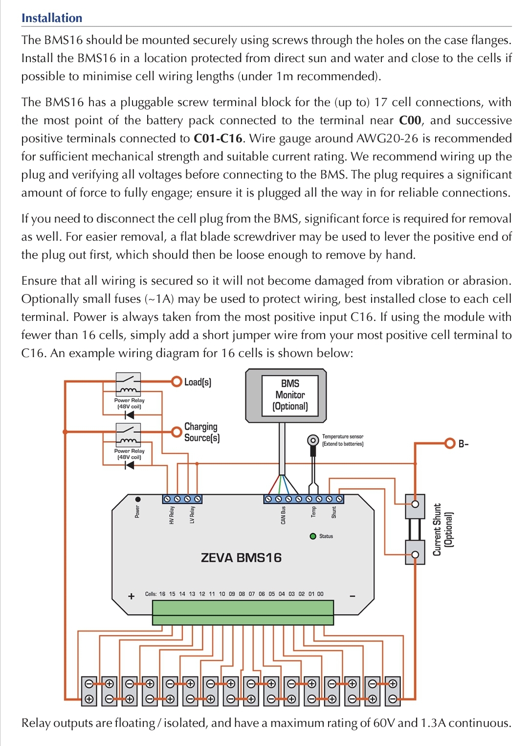
    Forgot to grab the manual this morning, but I've gone to the website and I think this is the relevant diagram.

    557634.jpg


  • Registered Users Posts: 12,199 ✭✭✭✭DrPhilG


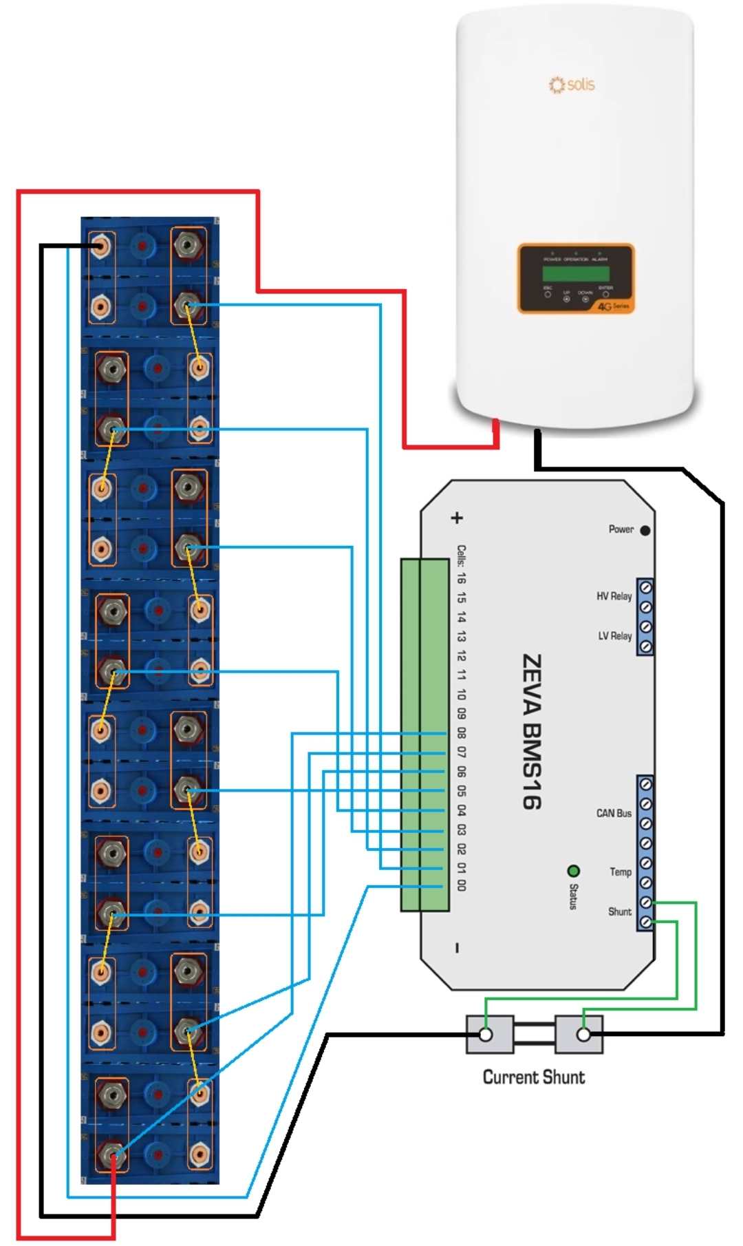
    OK. Be gentle... First draft and not finished yet.

    How does this look? This is based on 8 cells just to make the picture easier to post, but expand to 16 using the same logic.

    Combining the diagram from championc and the one from the BMS manual.

    557667.jpg


  • Registered Users Posts: 6,064 ✭✭✭championc


    DrPhilG wrote: »
    OK. Be gentle... First draft and not finished yet.

    How does this look? This is based on 8 cells just to make the picture easier to post, but expand to 16 using the same logic.

    Combining the diagram from championc and the one from the BMS manual.

    557667.jpg

    Yes, that looks spot on.

    Can I suggest that you flip the battery cells around so that no two wires cross. And I would suggest doing EXACTLY the same in real life, so you are matching everything exactly, leaving no place for error.

    Even then make a full 16 Cell diagram, print and laminate it and stick it on the wall, so it's damn clear for anyone (including yourself) in 5 years time.


  • Registered Users Posts: 12,199 ✭✭✭✭DrPhilG


    championc wrote: »
    Can I suggest that you flip the battery cells around so that no two wires cross.

    Yeah I was doing that in a hurry while at work, so you mean put the positive in at the top instead of the bottom and the negative starting at the bottom, then the bms cables go straight without overlapping?

    championc wrote: »
    And I would suggest doing EXACTLY the same in real life, so you are matching everything exactly, leaving no place for error.
    My thoughts exactly.

    Once I have the second shelf of batteries in place I'm going to take a photo and then photoshops the line diagrams directly onto them.

    2 shelves complicates things, but I'll put together some kind of mount and then wire from the top down and from the bottom up to meet in the middle.


  • Moderators, Home & Garden Moderators Posts: 5,798 Mod ✭✭✭✭graememk


    Next thing to think about, the CAN Battery connection

    Plyontech's use a RJ45 connector, But only 2 of the wires are used in that cable

    - It is not Ethernet!

    in the solis manual it says only pin4 (blue) and pin5 (blue/white) are used for communication.

    and then I found this website, (its for victron) but tells us what we need to know.
    https://www.victronenergy.com/live/battery_compatibility:can-bus_bms-cable
    (on the RJ45 cable you have)
    Pin4 is CAN H
    Pin5 is CAN L


  • Registered Users Posts: 12,199 ✭✭✭✭DrPhilG


    graememk wrote: »
    in the solis manual it says only pin4 (blue) and pin5 (blue/white) are used for communication.

    and then I found this website, (its for victron) but tells us what we need to know.
    https://www.victronenergy.com/live/battery_compatibility:can-bus_bms-cable
    (on the RJ45 cable you have)
    Pin4 is CAN H
    Pin5 is CAN L
    The manual diagram shows 4 cables from can to the monitor. I'll check with the manufacturer.


  • Advertisement
  • Registered Users Posts: 6,064 ✭✭✭championc


    DrPhilG wrote: »
    Yeah I was doing that in a hurry while at work, so you mean put the positive in at the top instead of the bottom and the negative starting at the bottom, then the bms cables go straight without overlapping?


    My thoughts exactly.

    Once I have the second shelf of batteries in place I'm going to take a photo and then photoshops the line diagrams directly onto them.

    2 shelves complicates things, but I'll put together some kind of mount and then wire from the top down and from the bottom up to meet in the middle.

    Be prepared to run the cable between halves of the battery string, from the right hand end off one onto the the left hand end onto the other. It's a longer run but keeps your string as though it's one long line (just split in two halves)


Advertisement