Advertisement
If you have a new account but are having problems posting or verifying your account, please email us on hello@boards.ie for help. Thanks :)
Hello all! Please ensure that you are posting a new thread or question in the appropriate forum. The Feedback forum is overwhelmed with questions that are having to be moved elsewhere. If you need help to verify your account contact hello@boards.ie
Hi all! We have been experiencing an issue on site where threads have been missing the latest postings. The platform host Vanilla are working on this issue. A workaround that has been used by some is to navigate back from 1 to 10+ pages to re-sync the thread and this will then show the latest posts. Thanks, Mike.
Hi there,
There is an issue with role permissions that is being worked on at the moment.
If you are having trouble with access or permissions on regional forums please post here to get access: https://www.boards.ie/discussion/2058365403/you-do-not-have-permission-for-that#latest

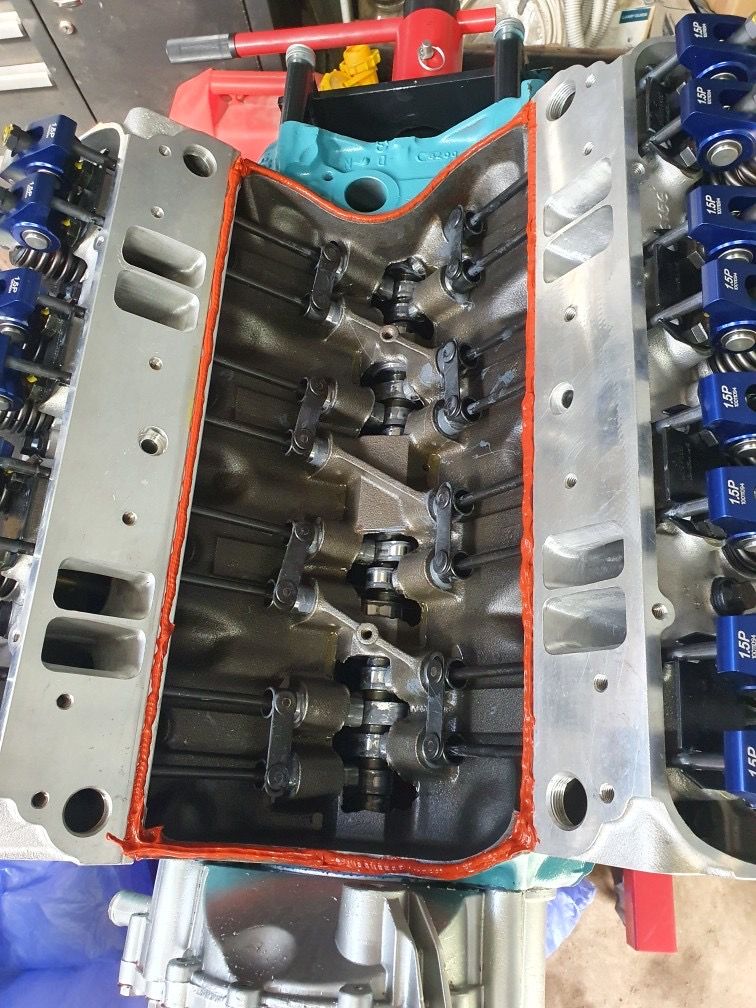
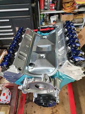
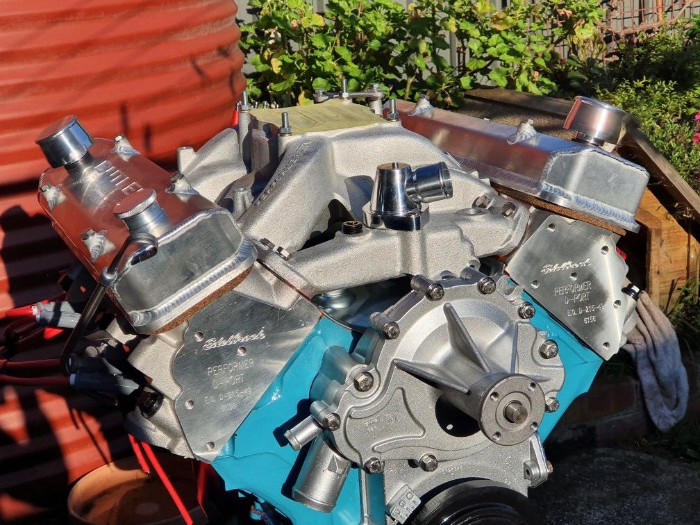
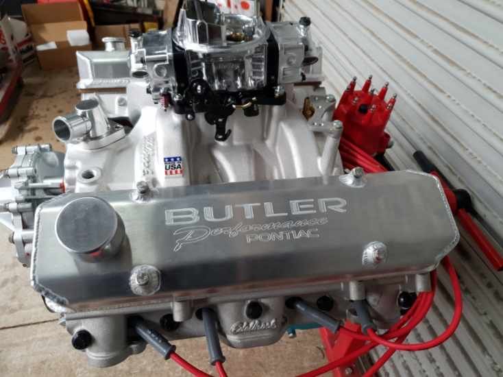
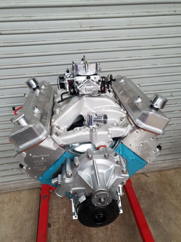
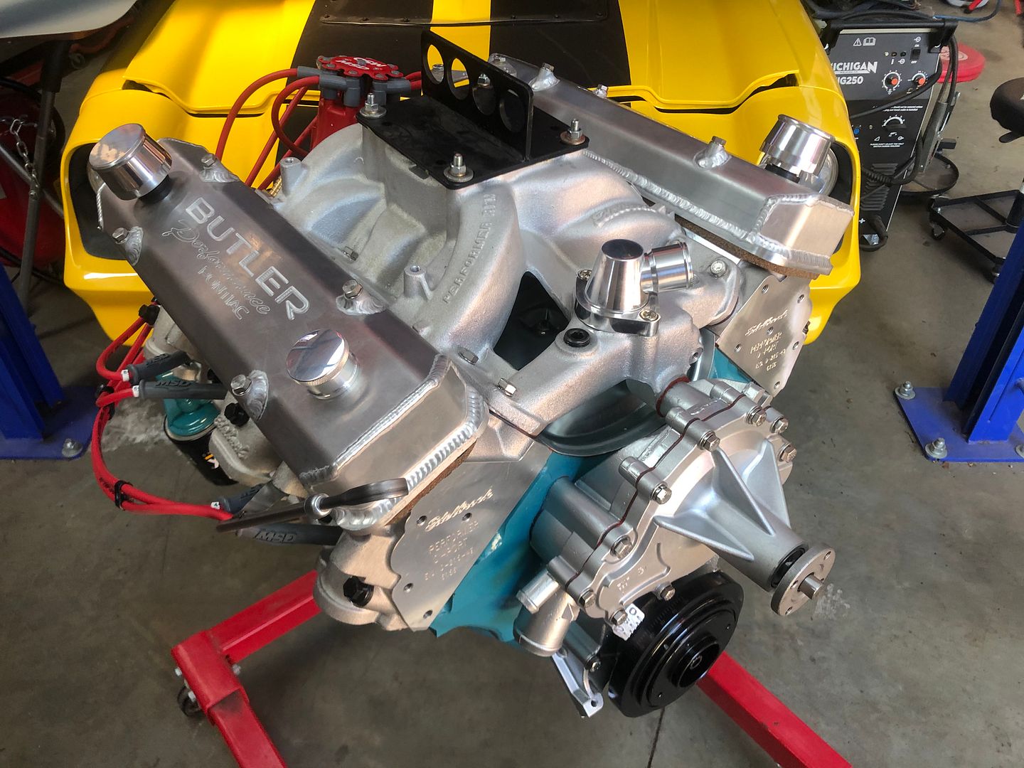
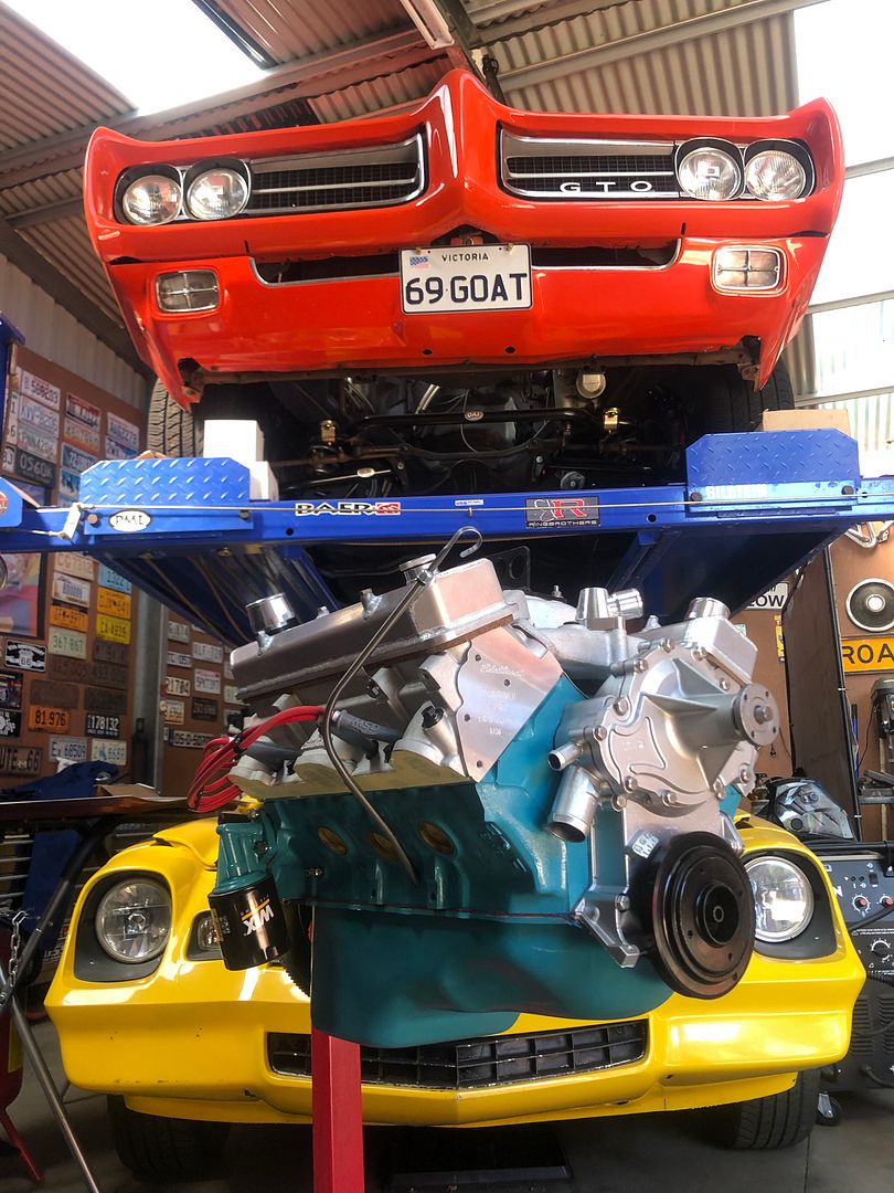
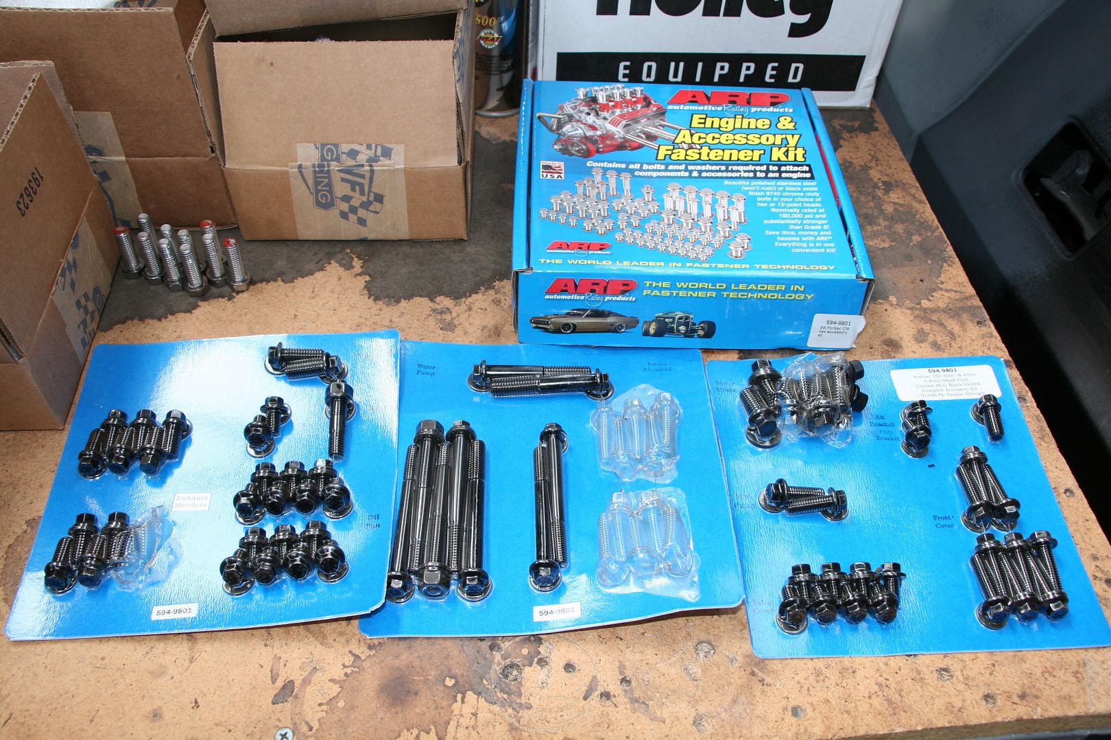
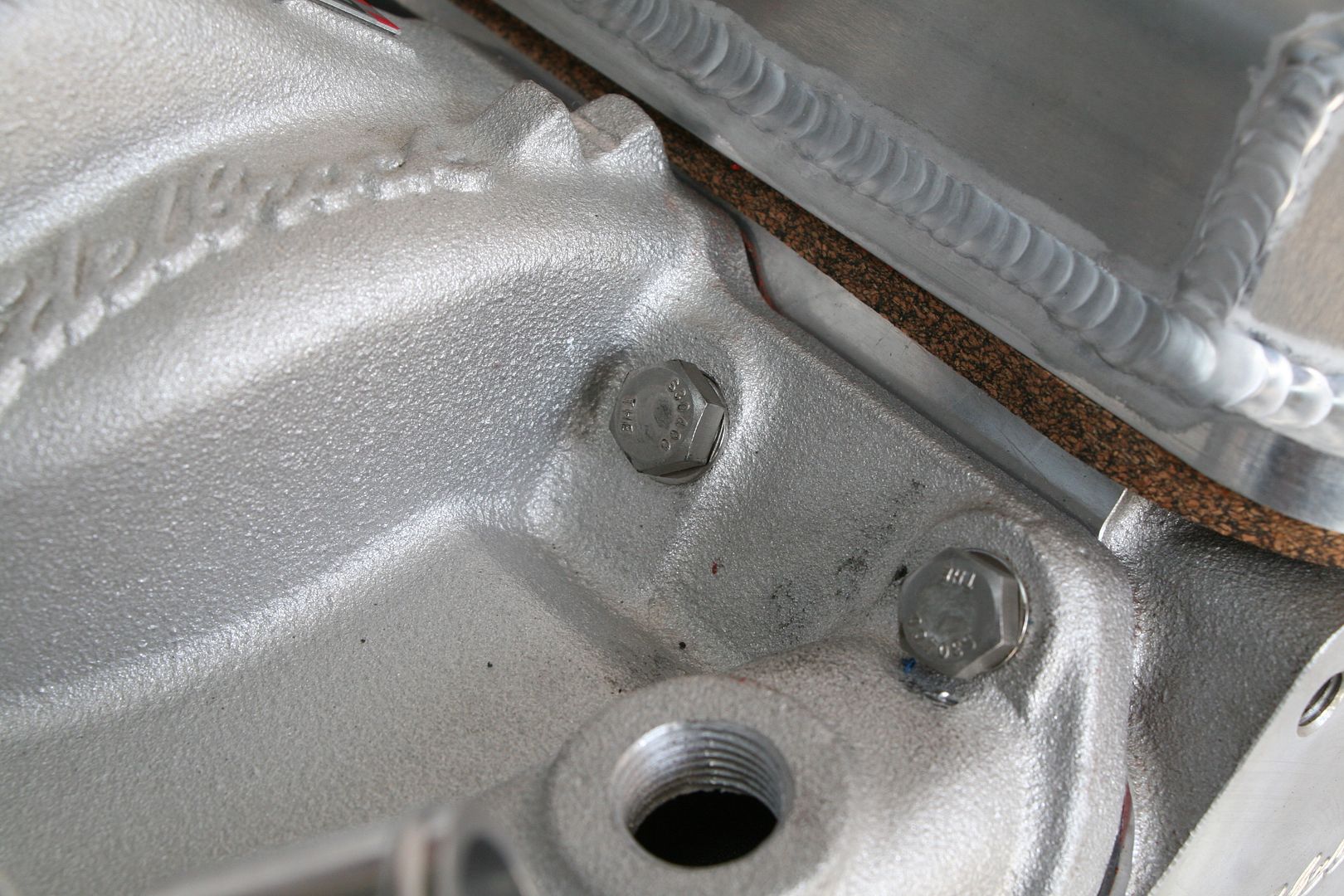
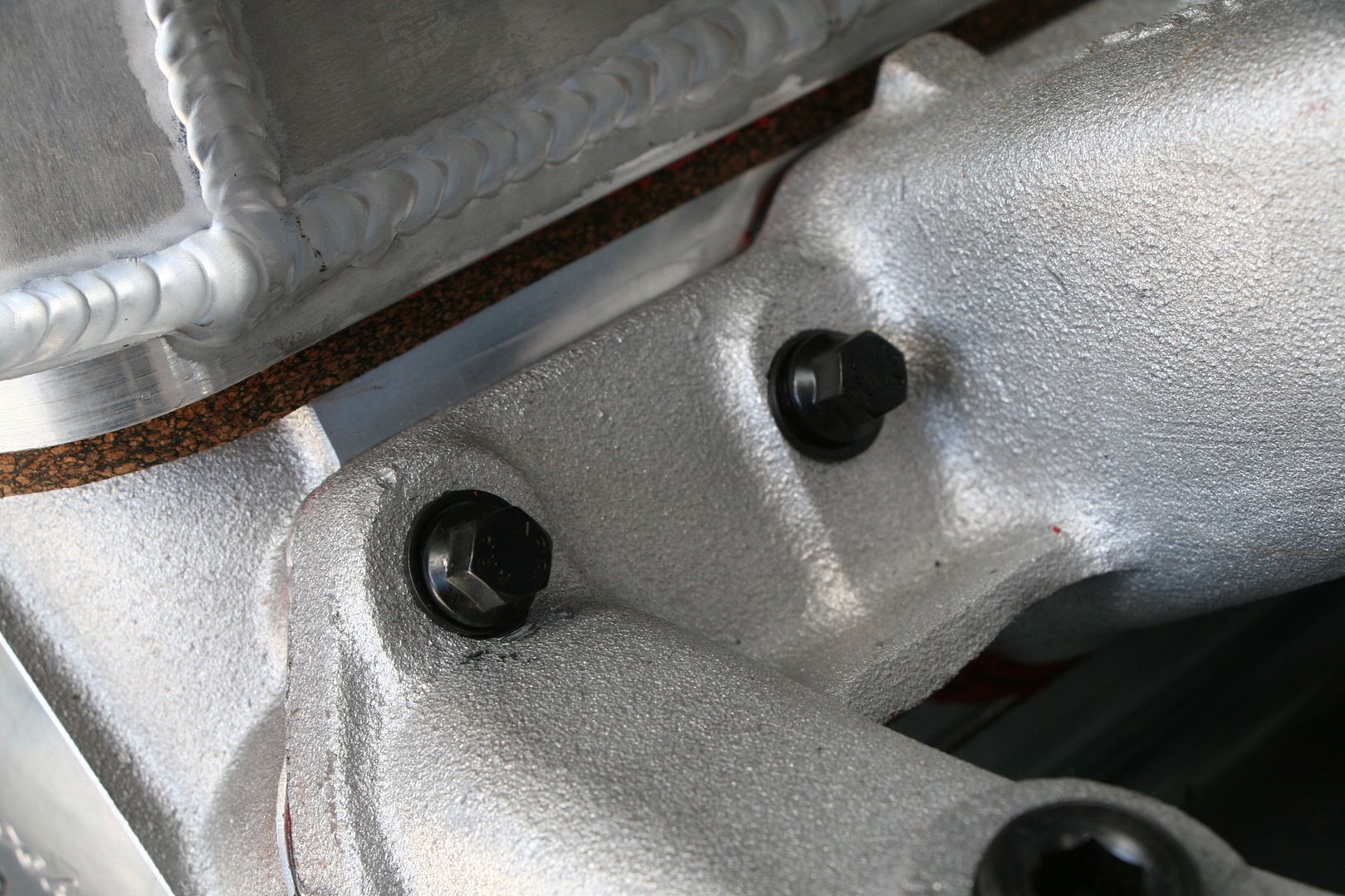
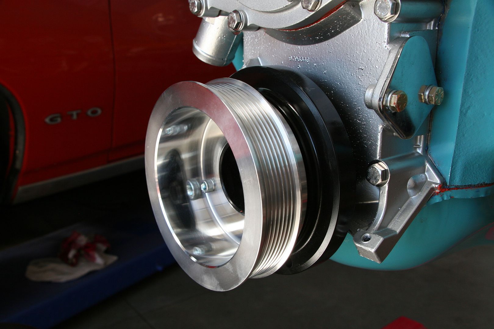
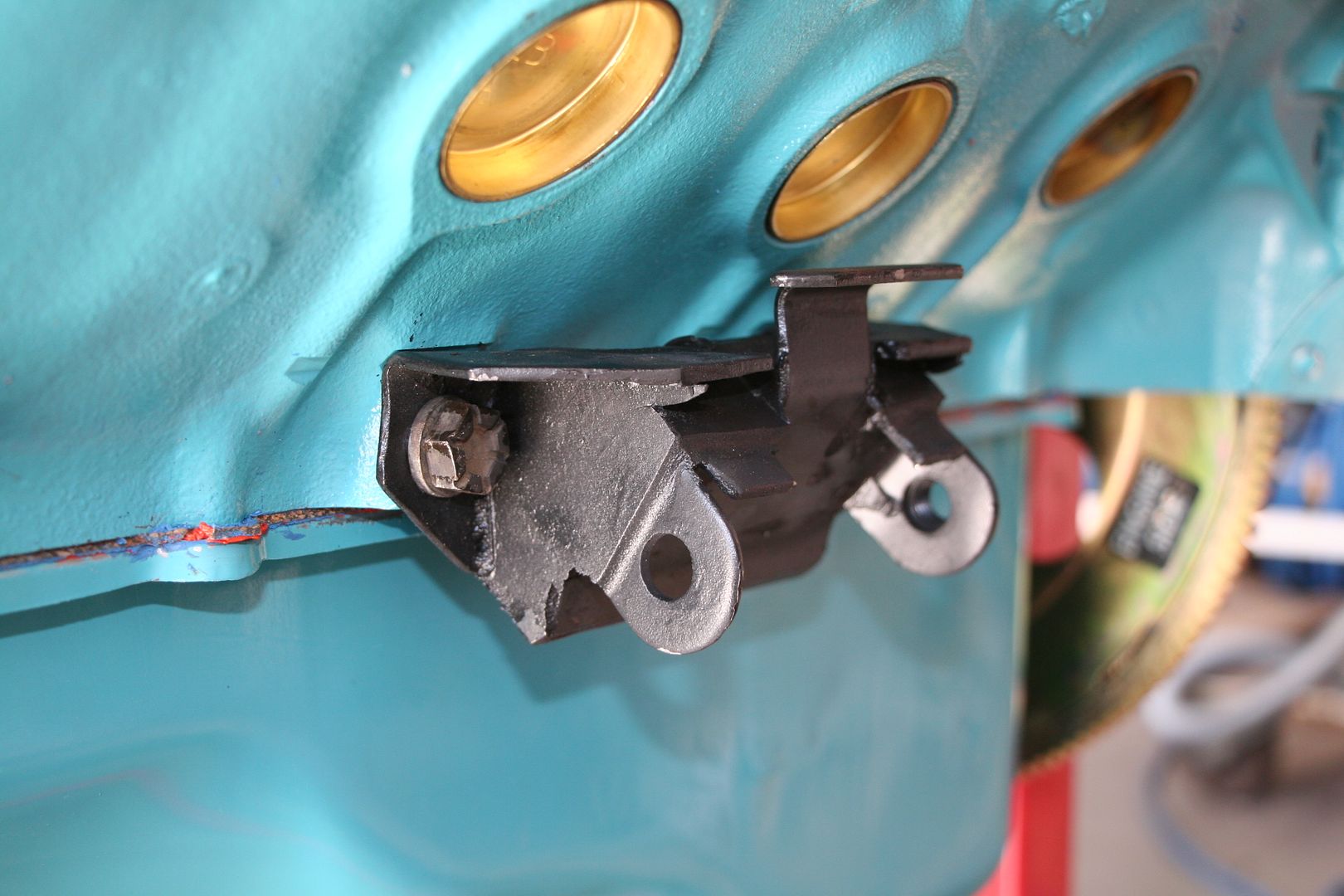
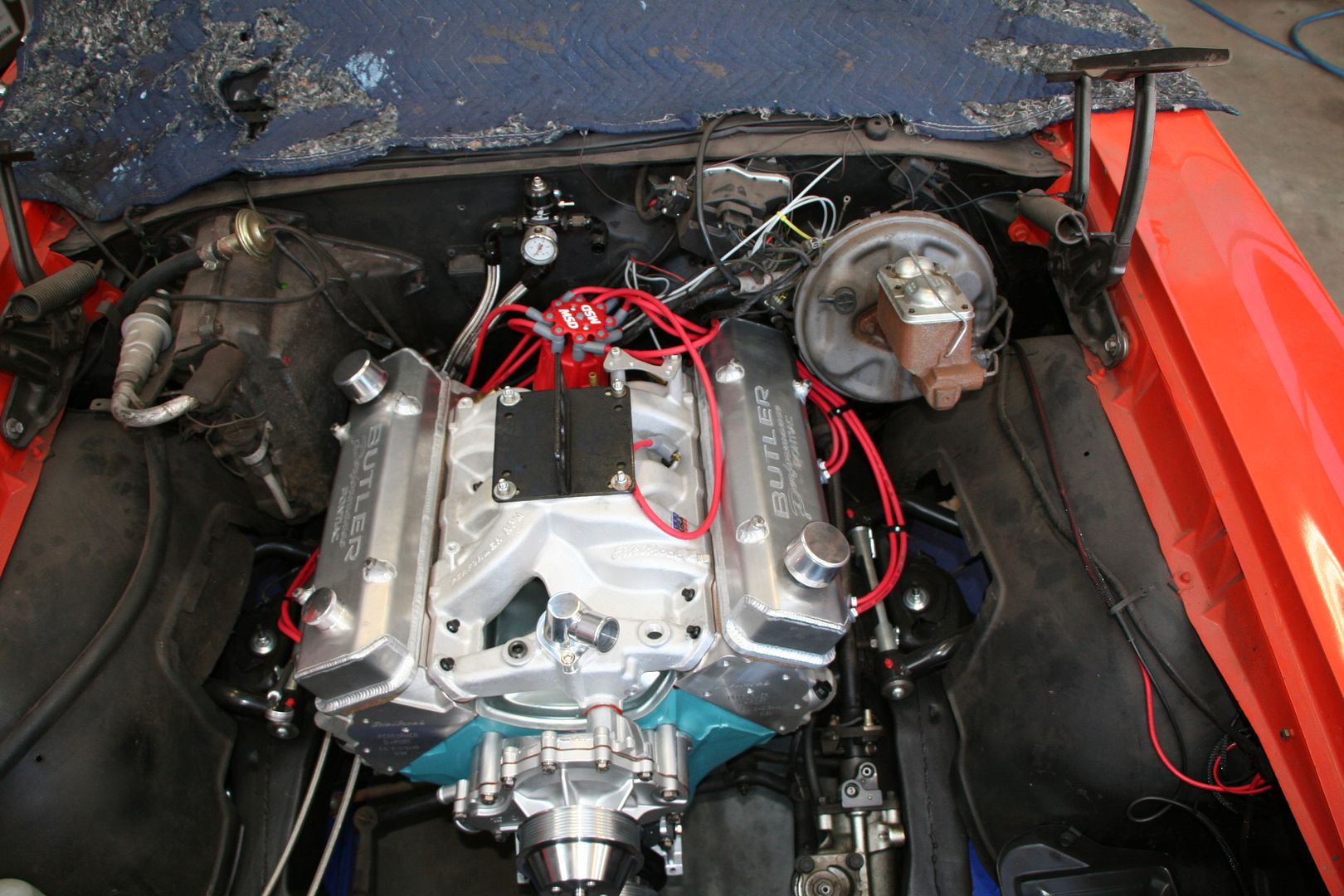
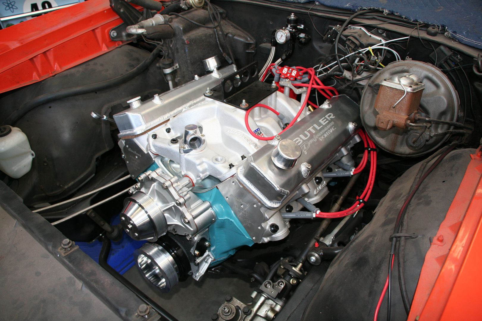
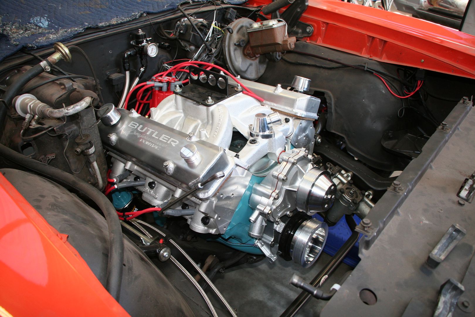
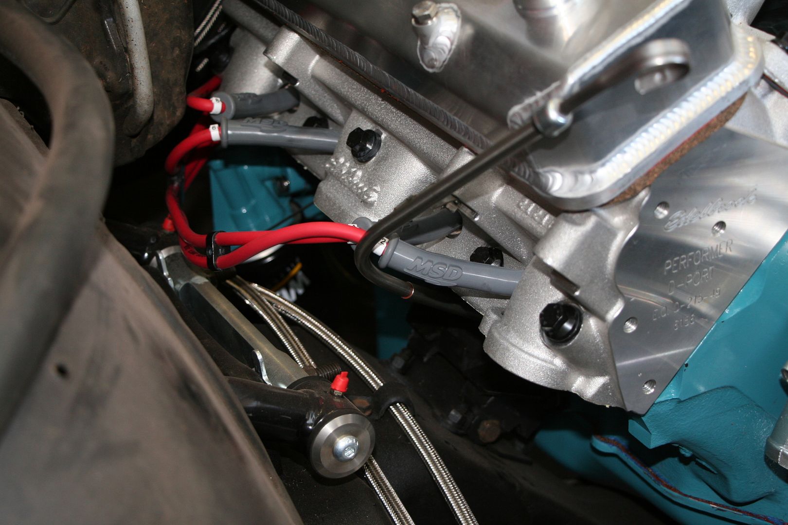
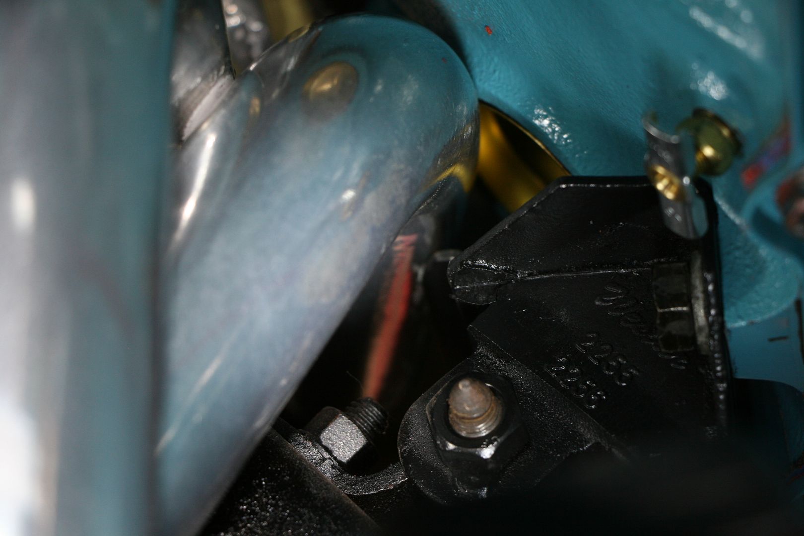
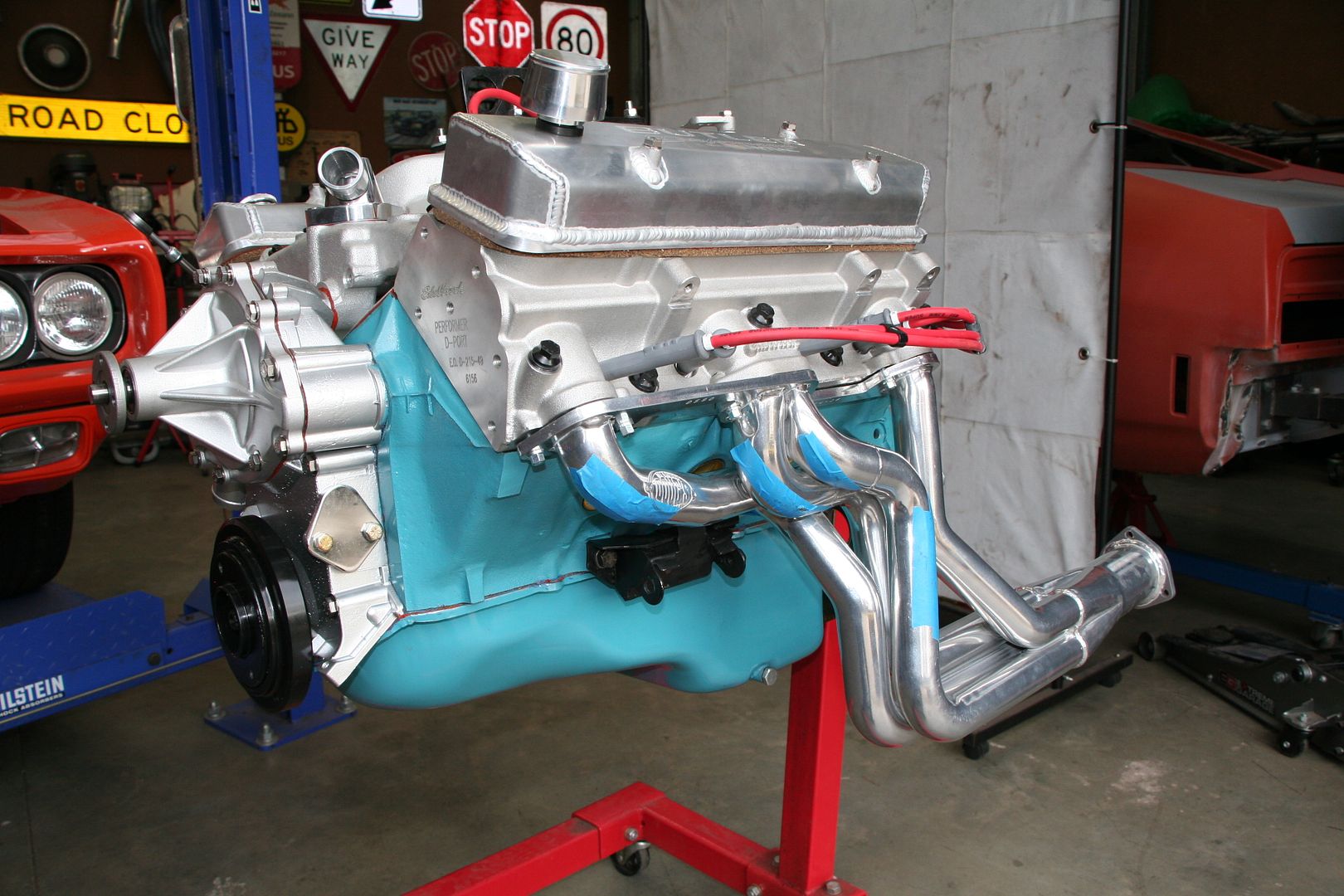
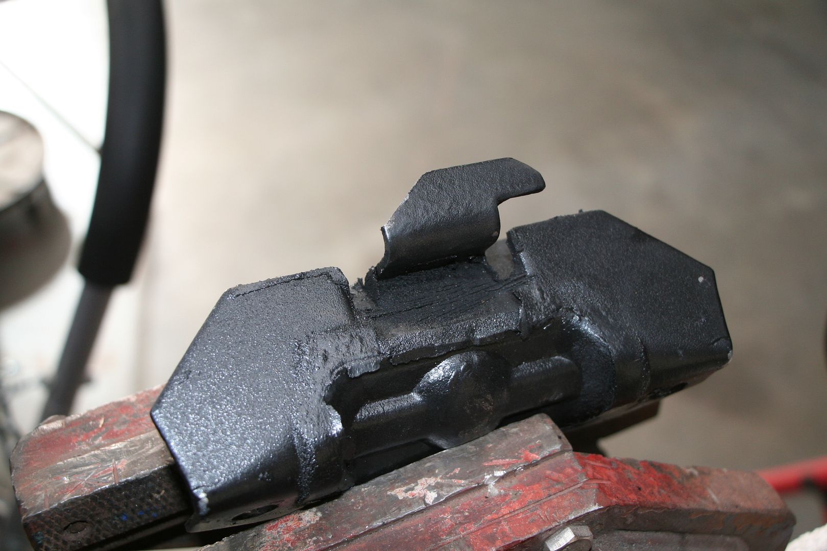
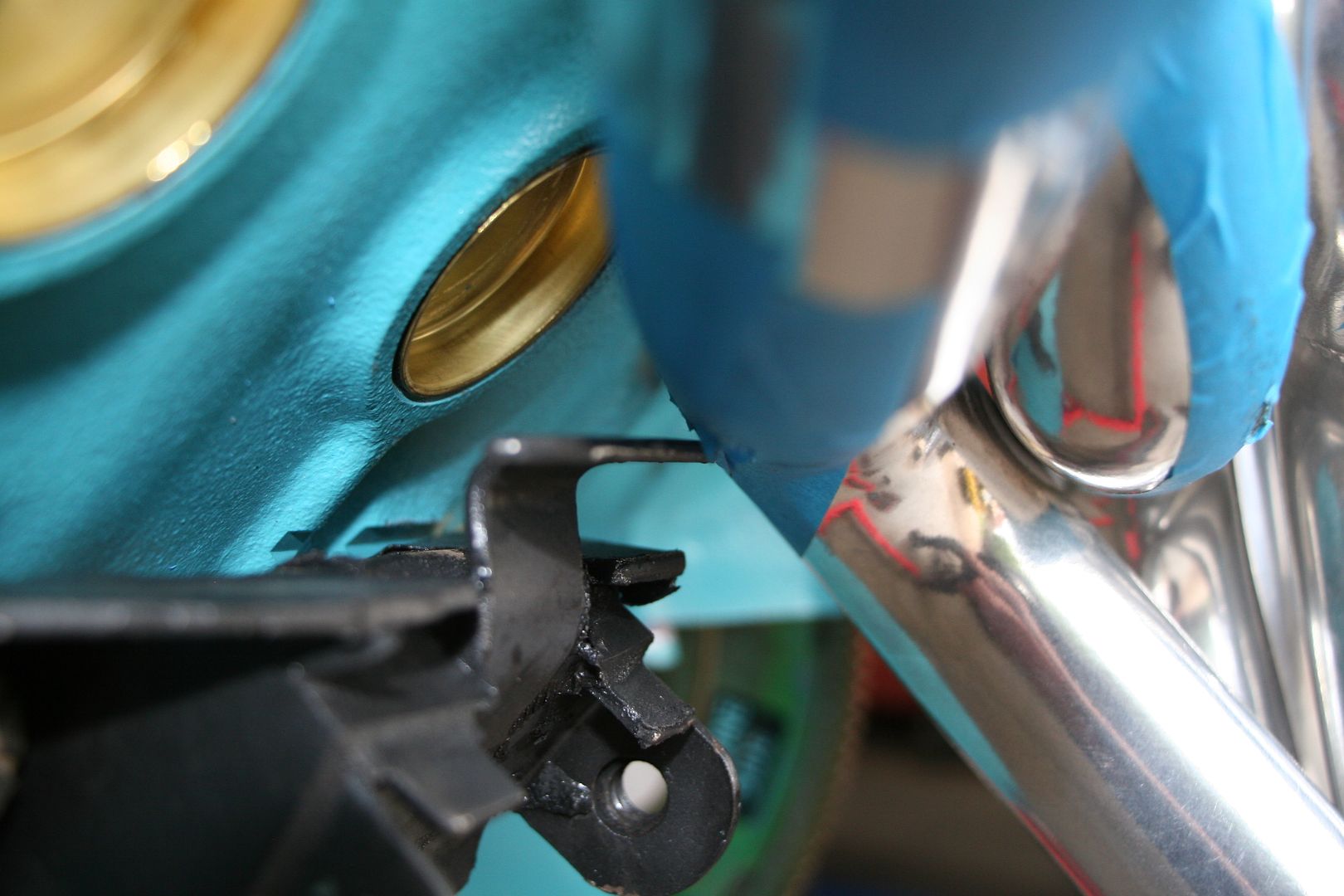
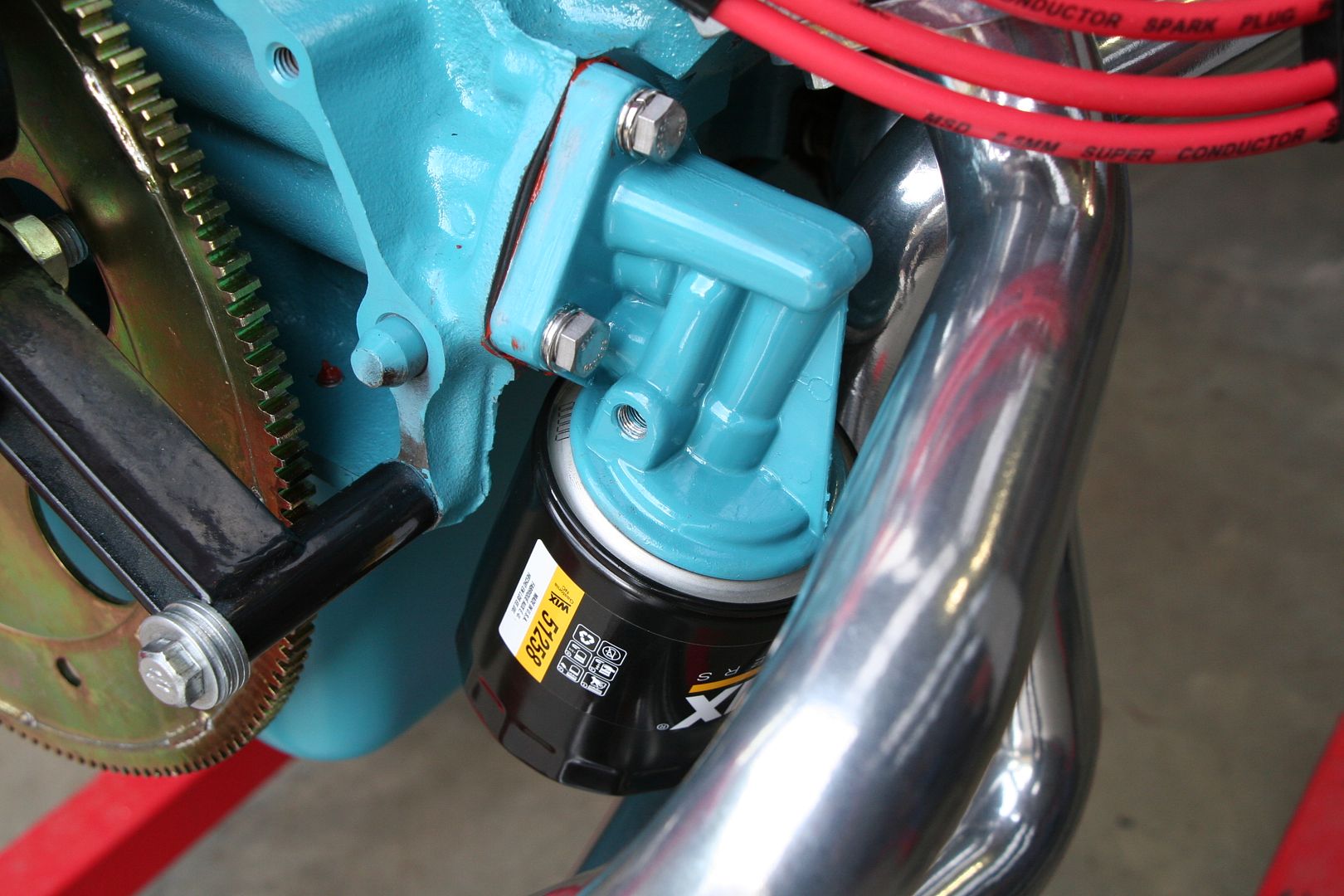
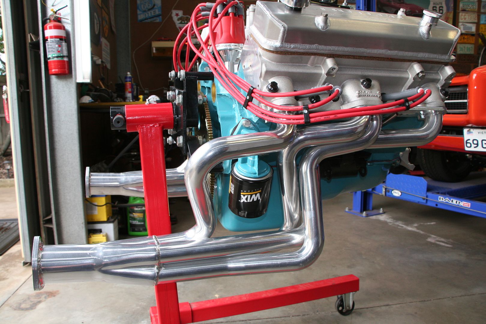
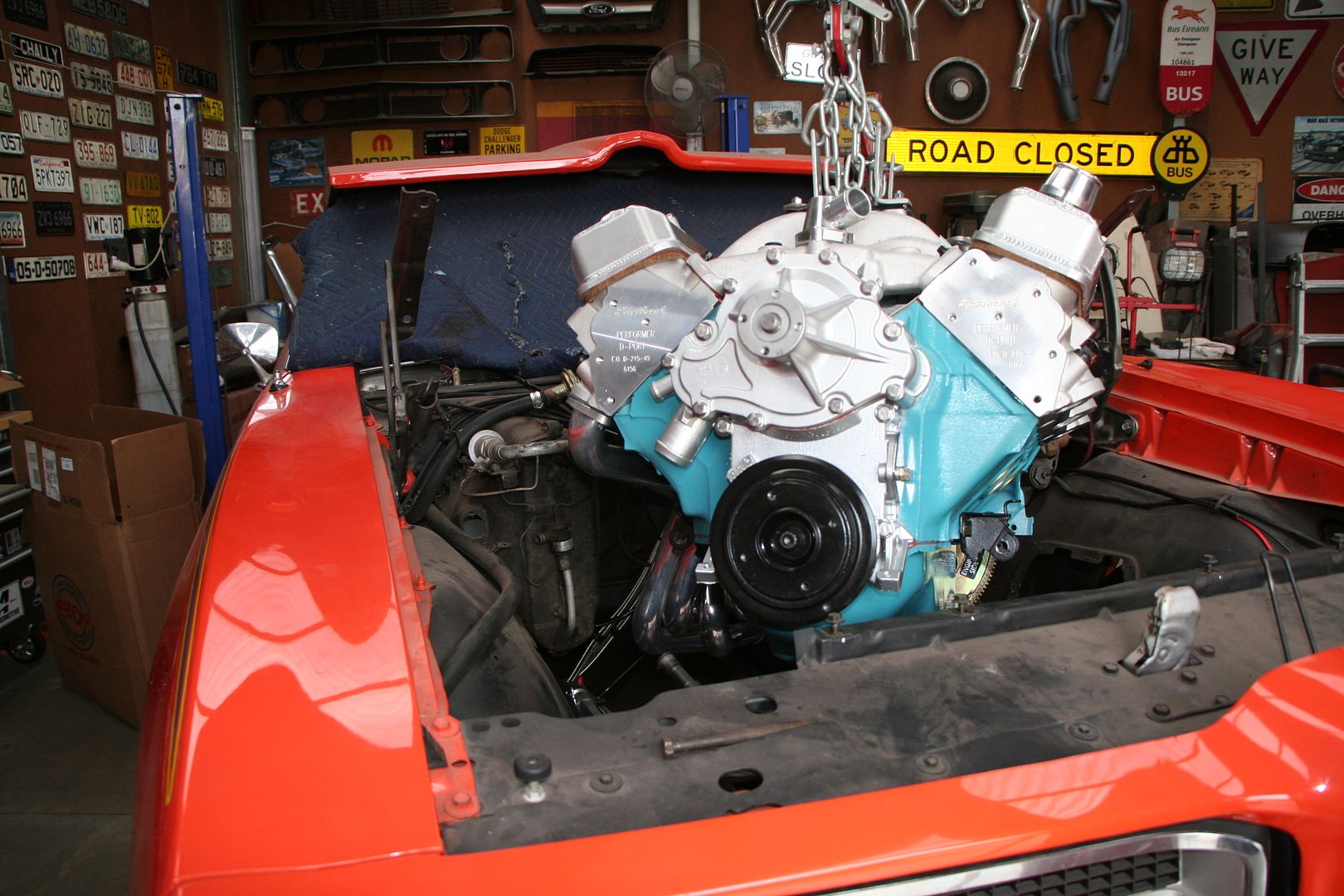
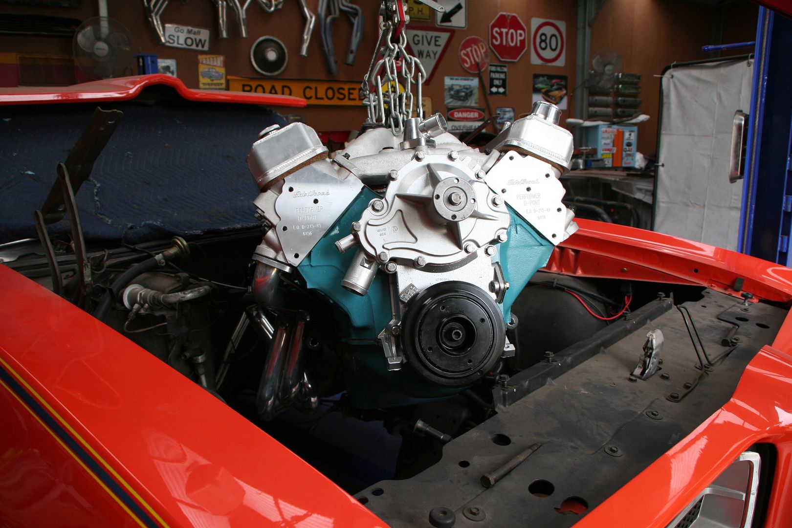
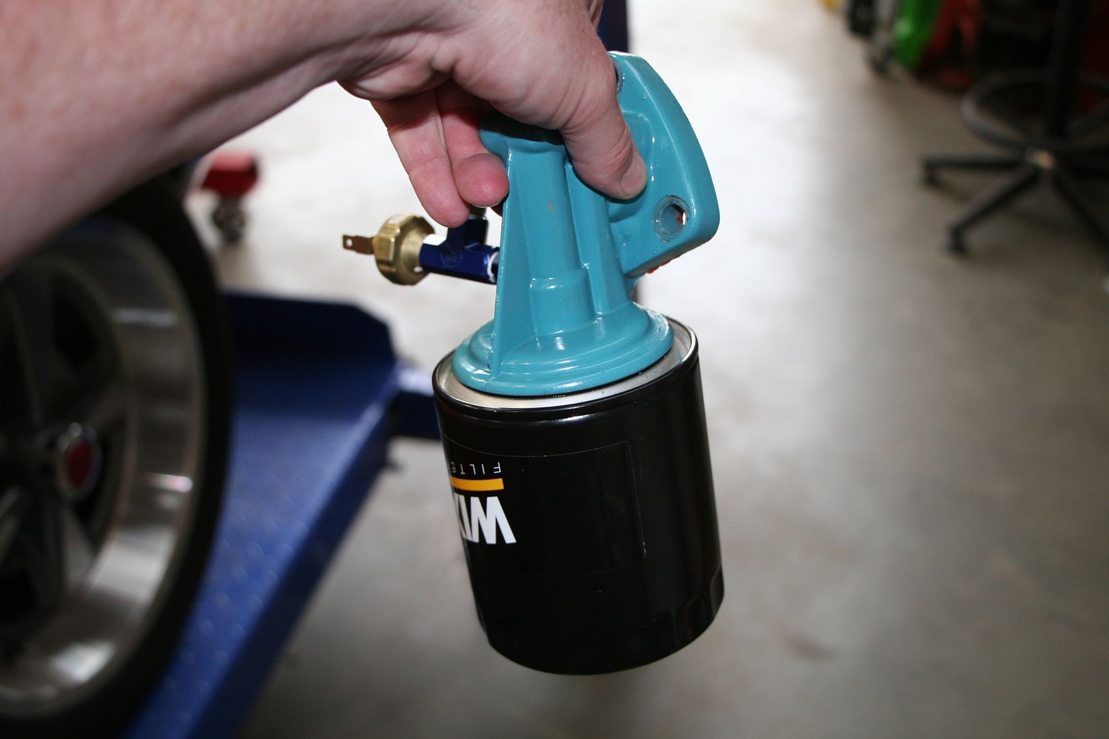
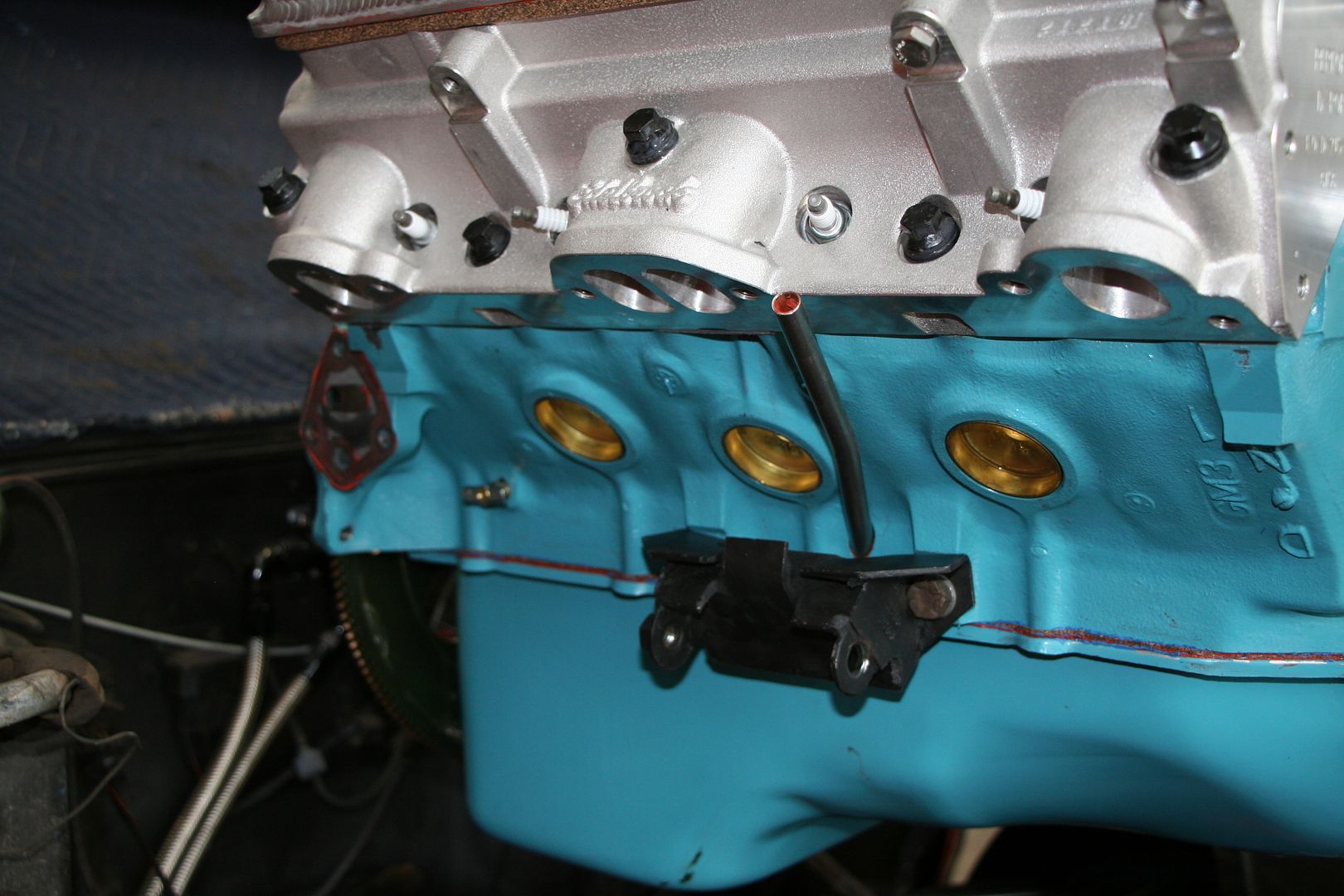
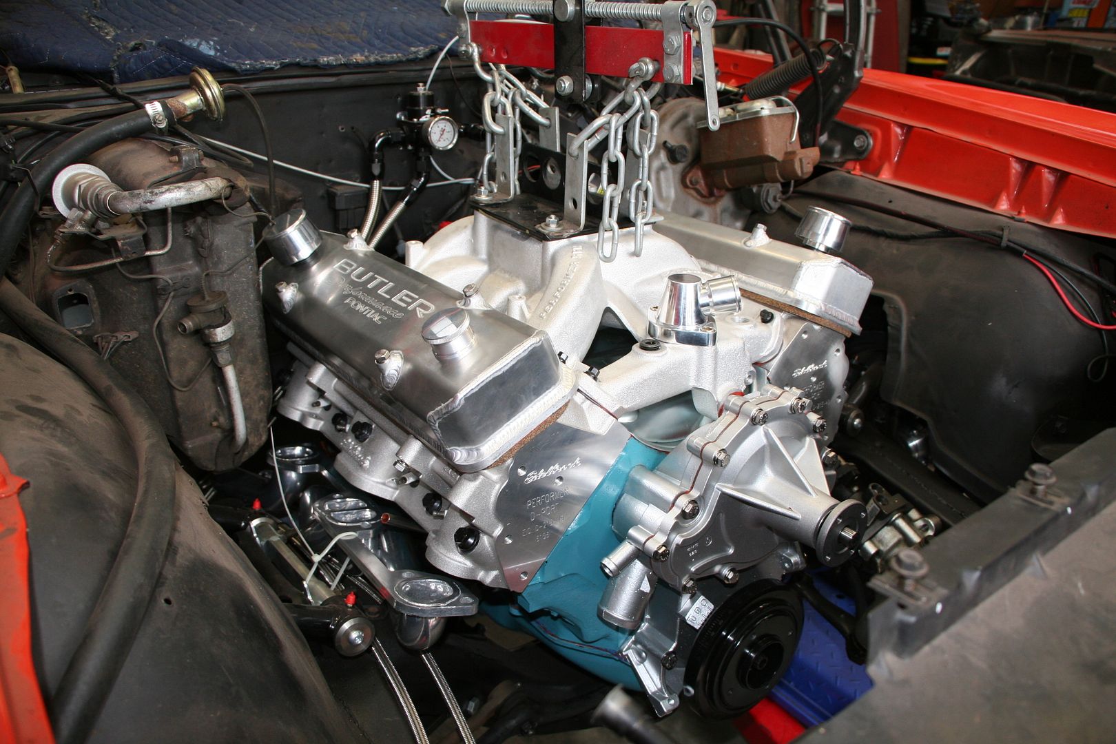
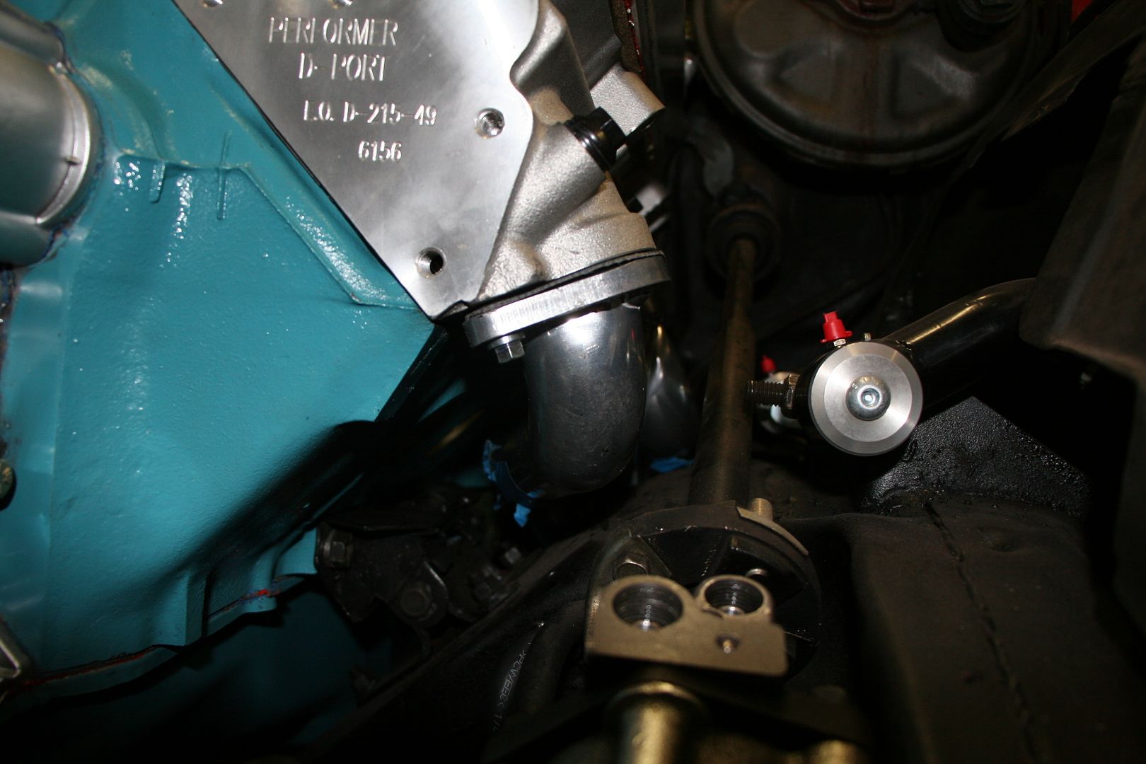
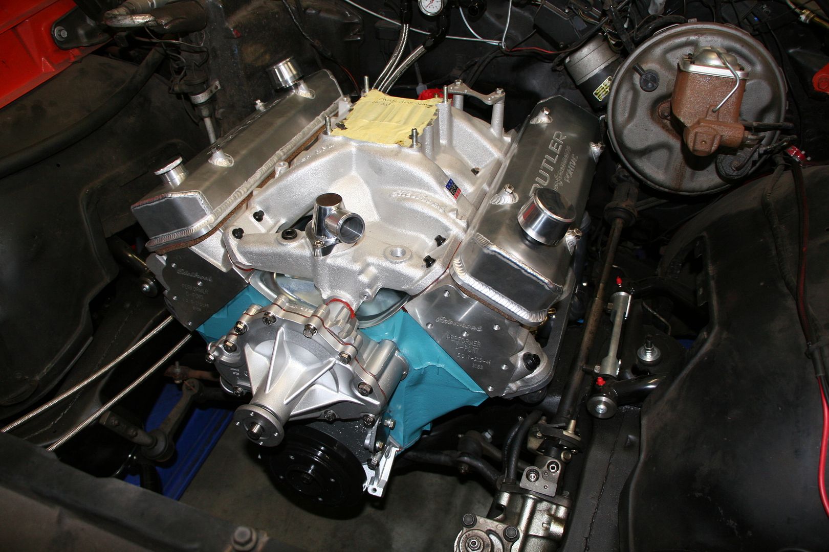
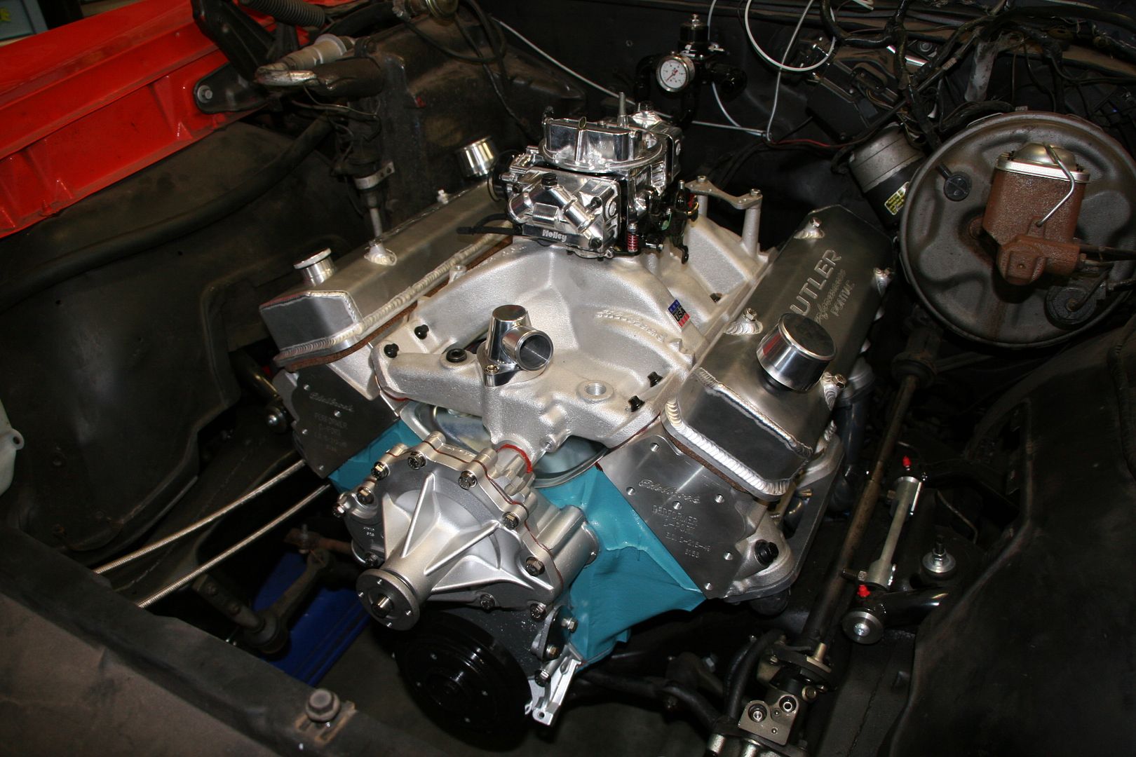
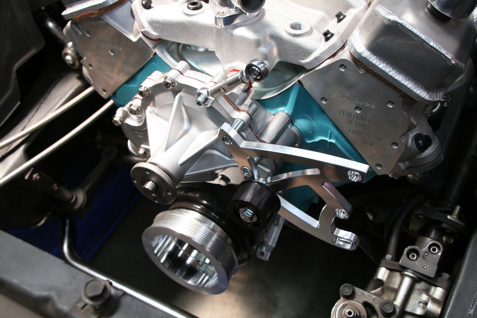
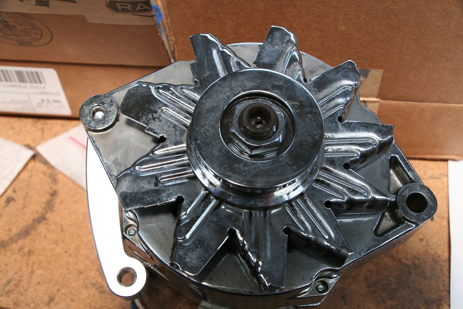
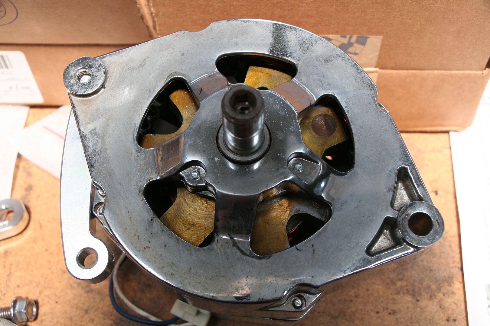
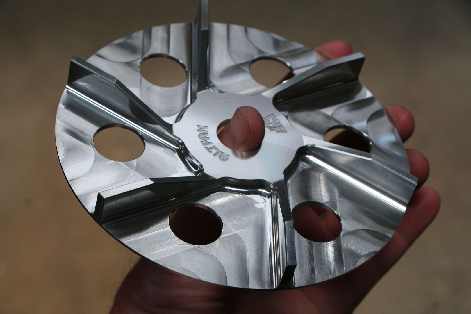
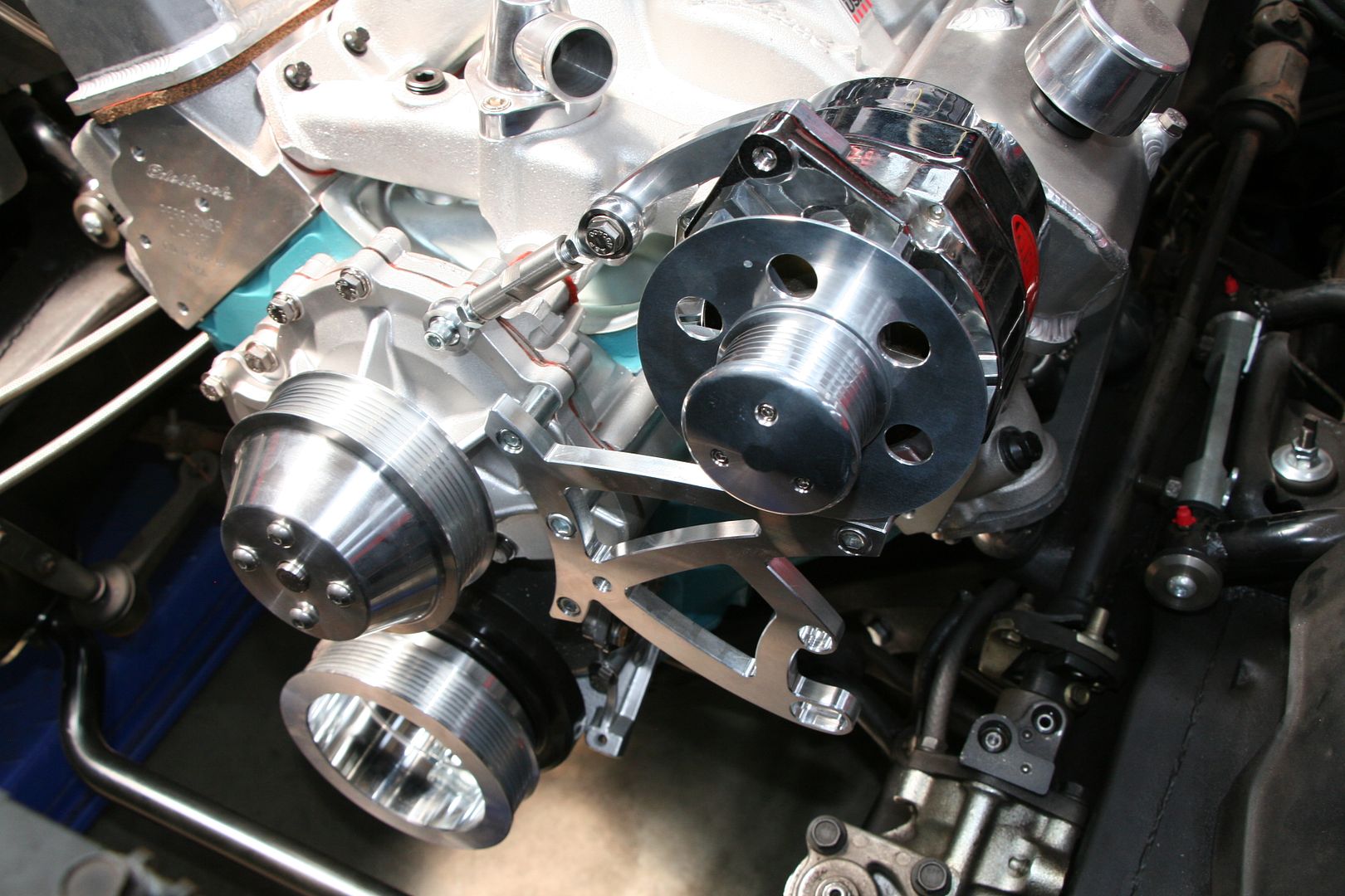
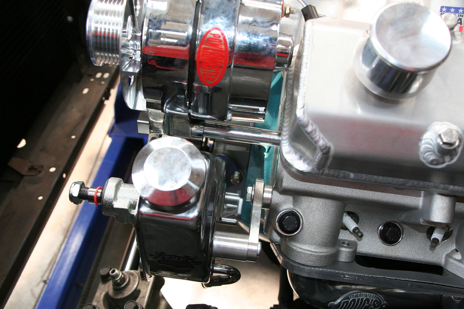
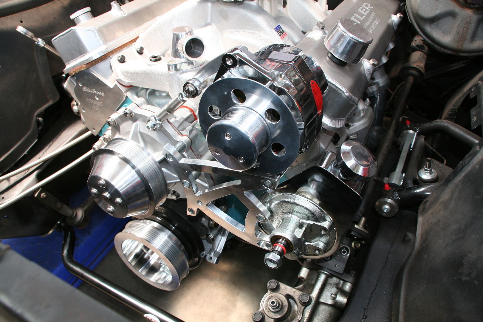
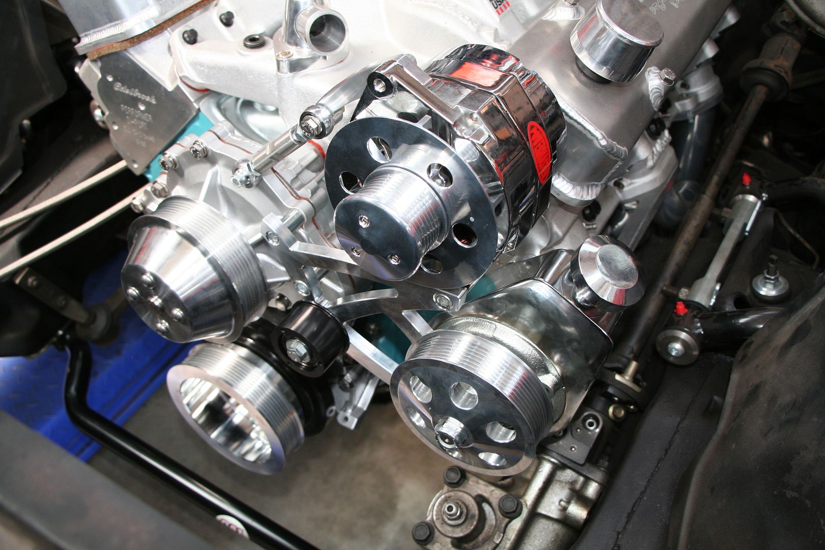
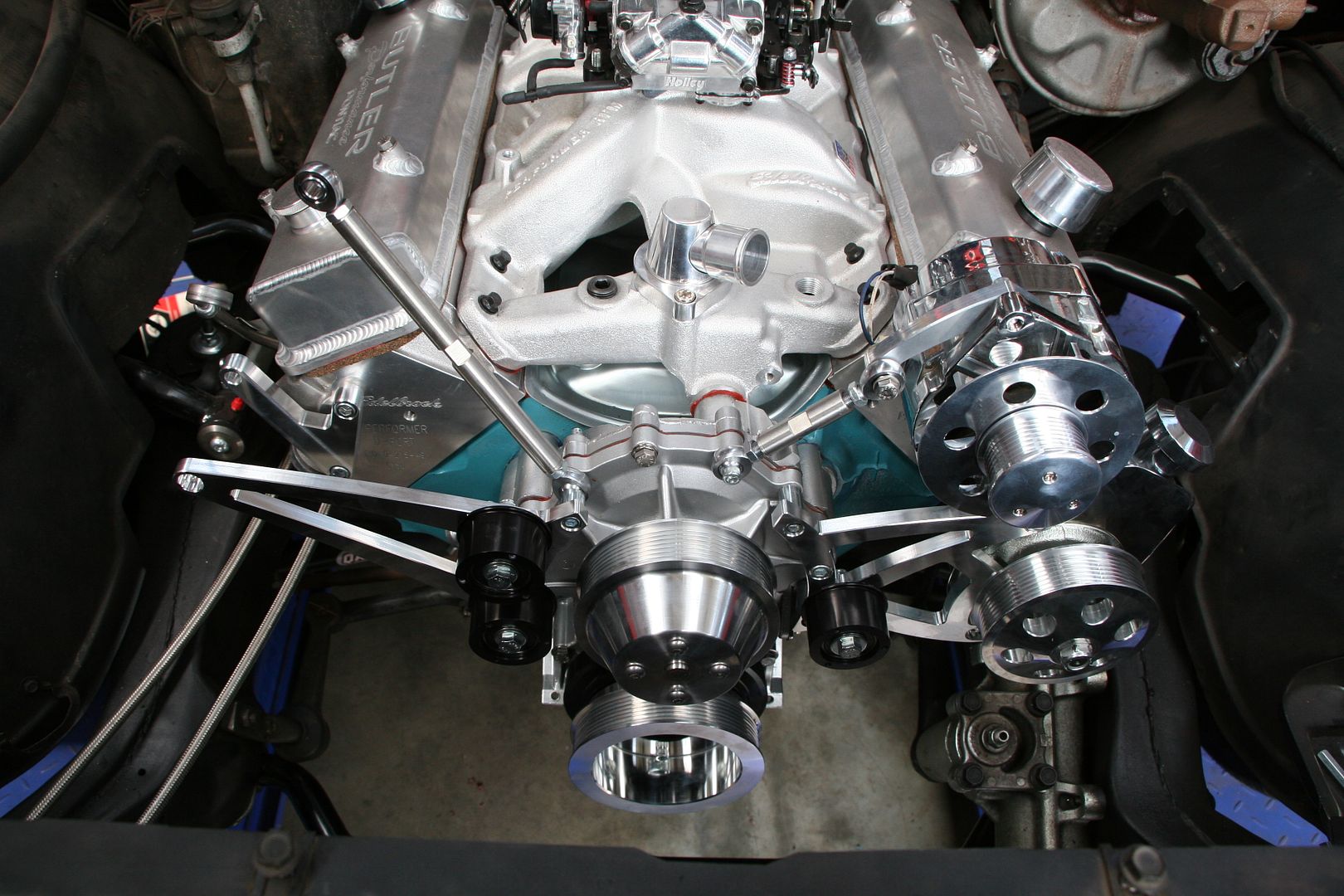
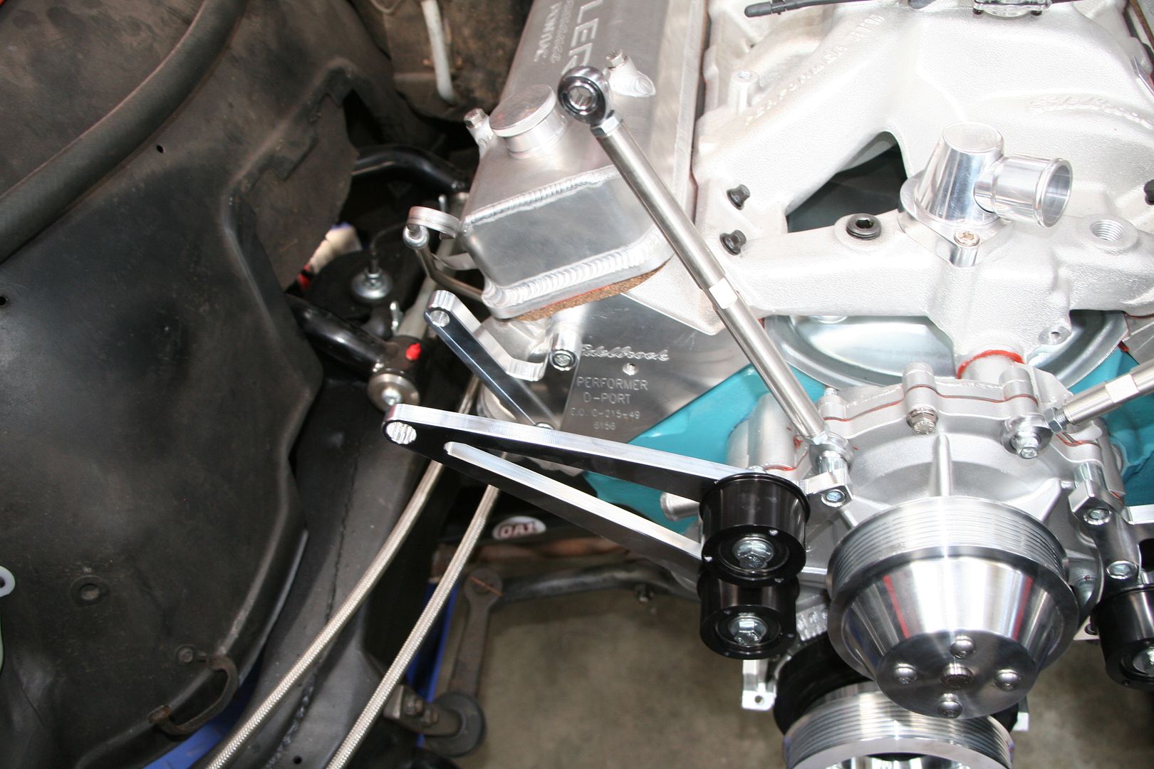
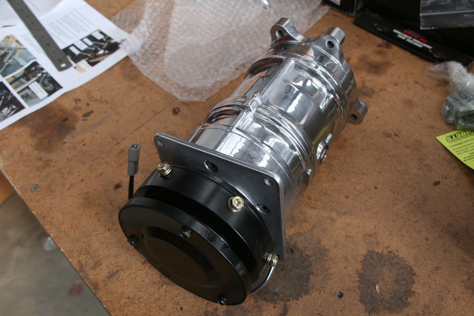
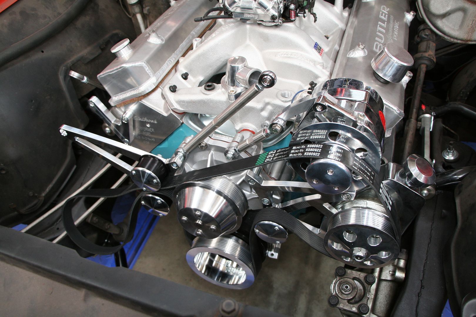
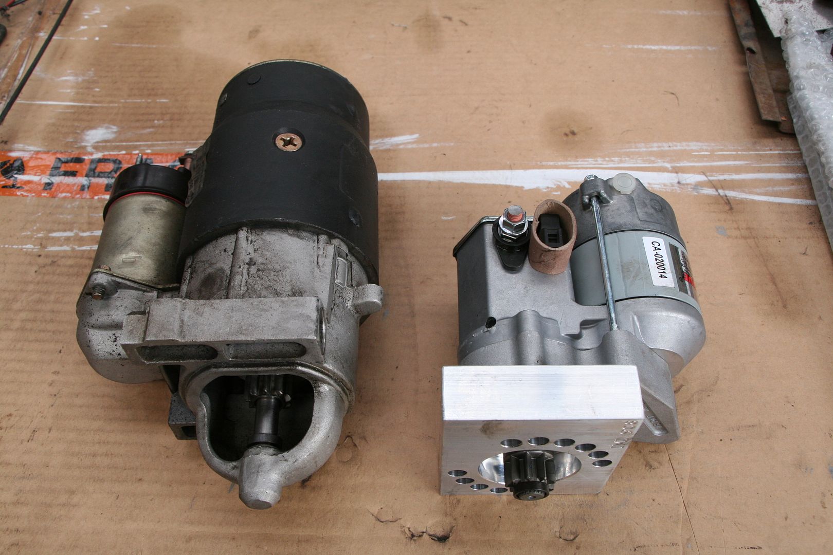
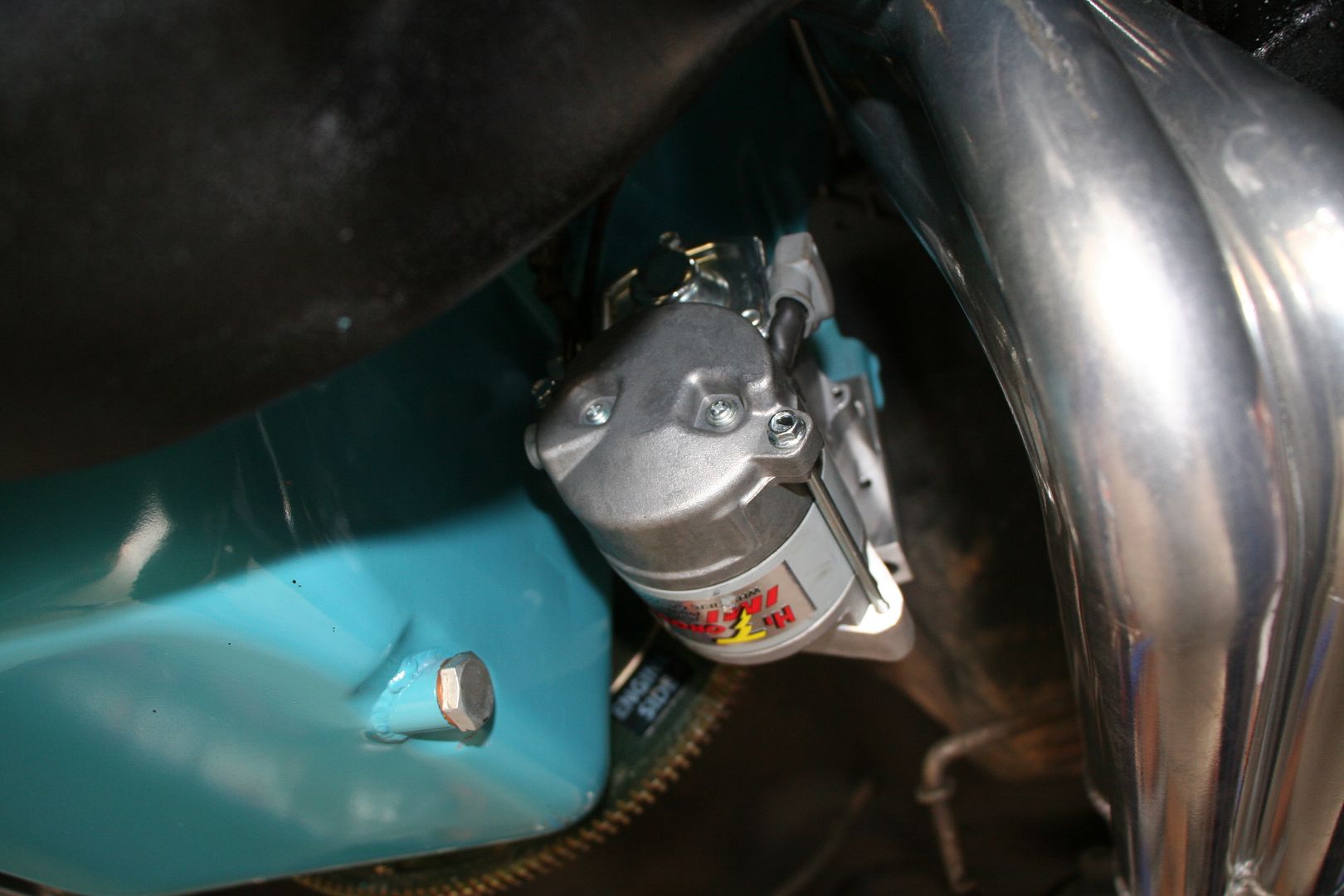
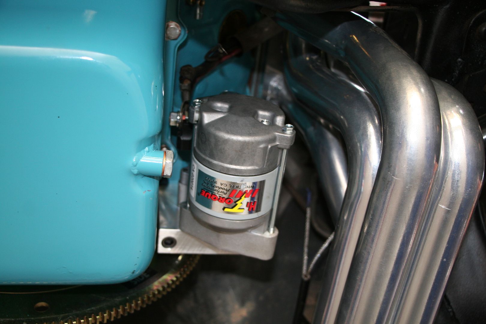
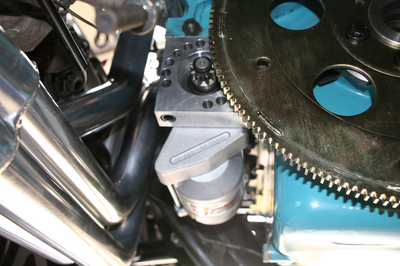
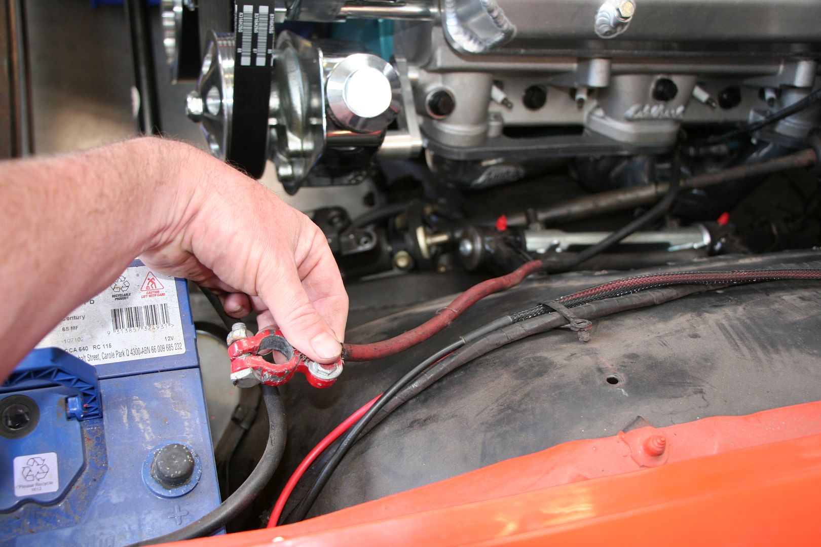
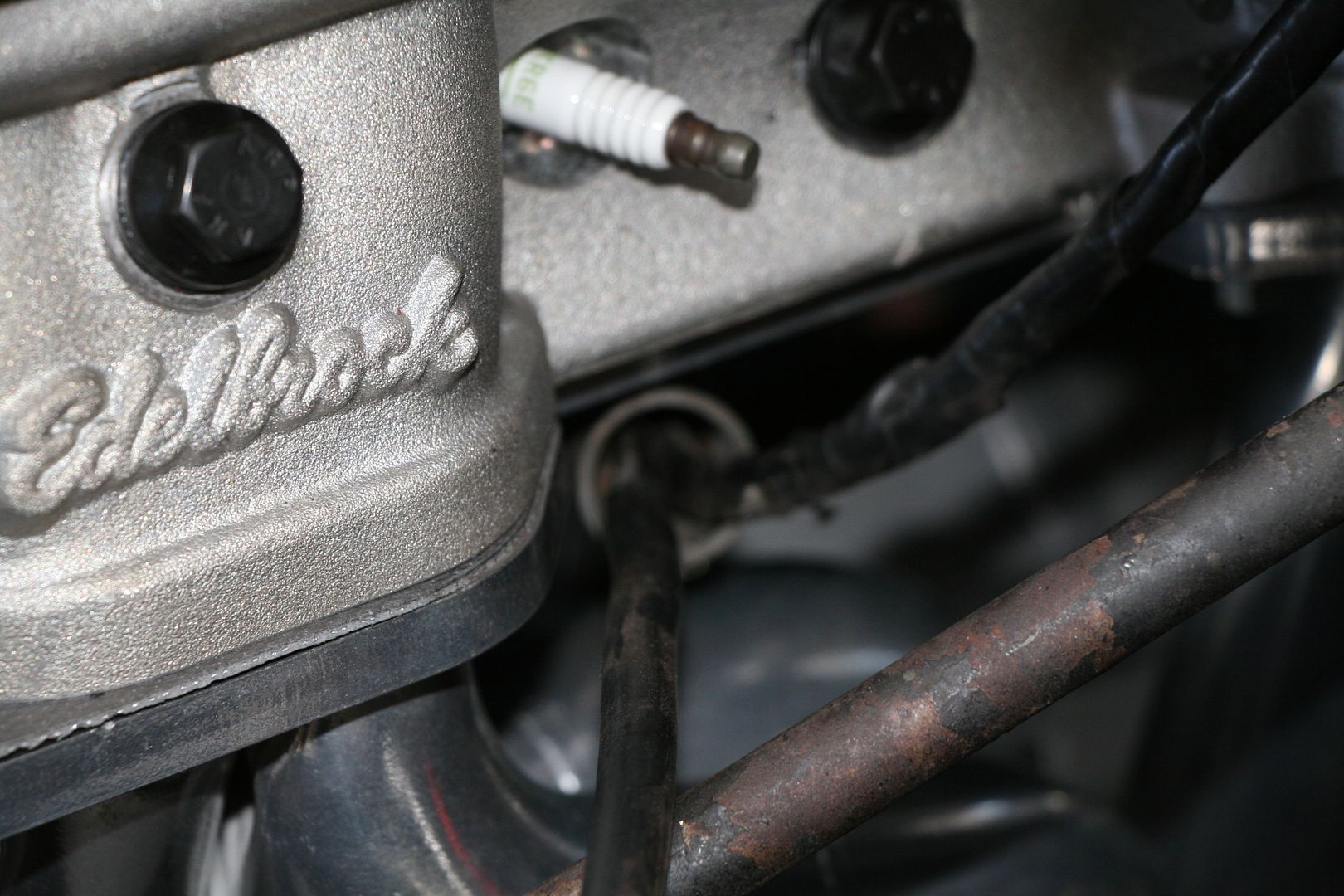
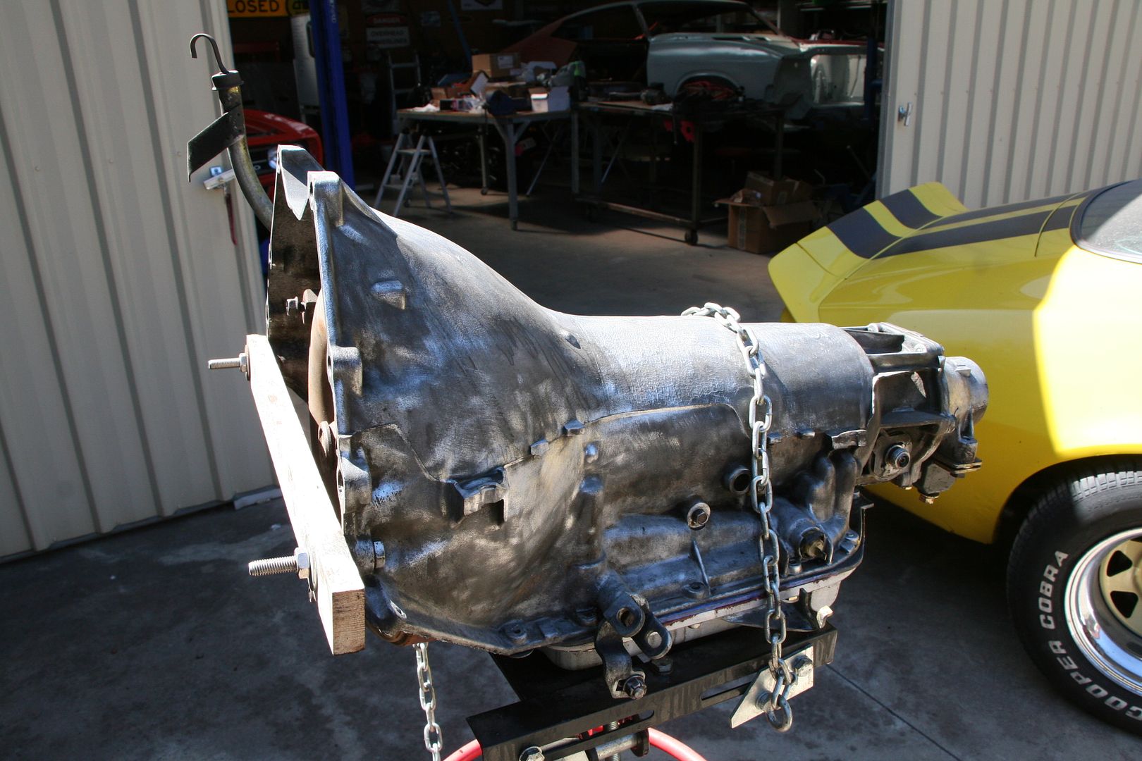
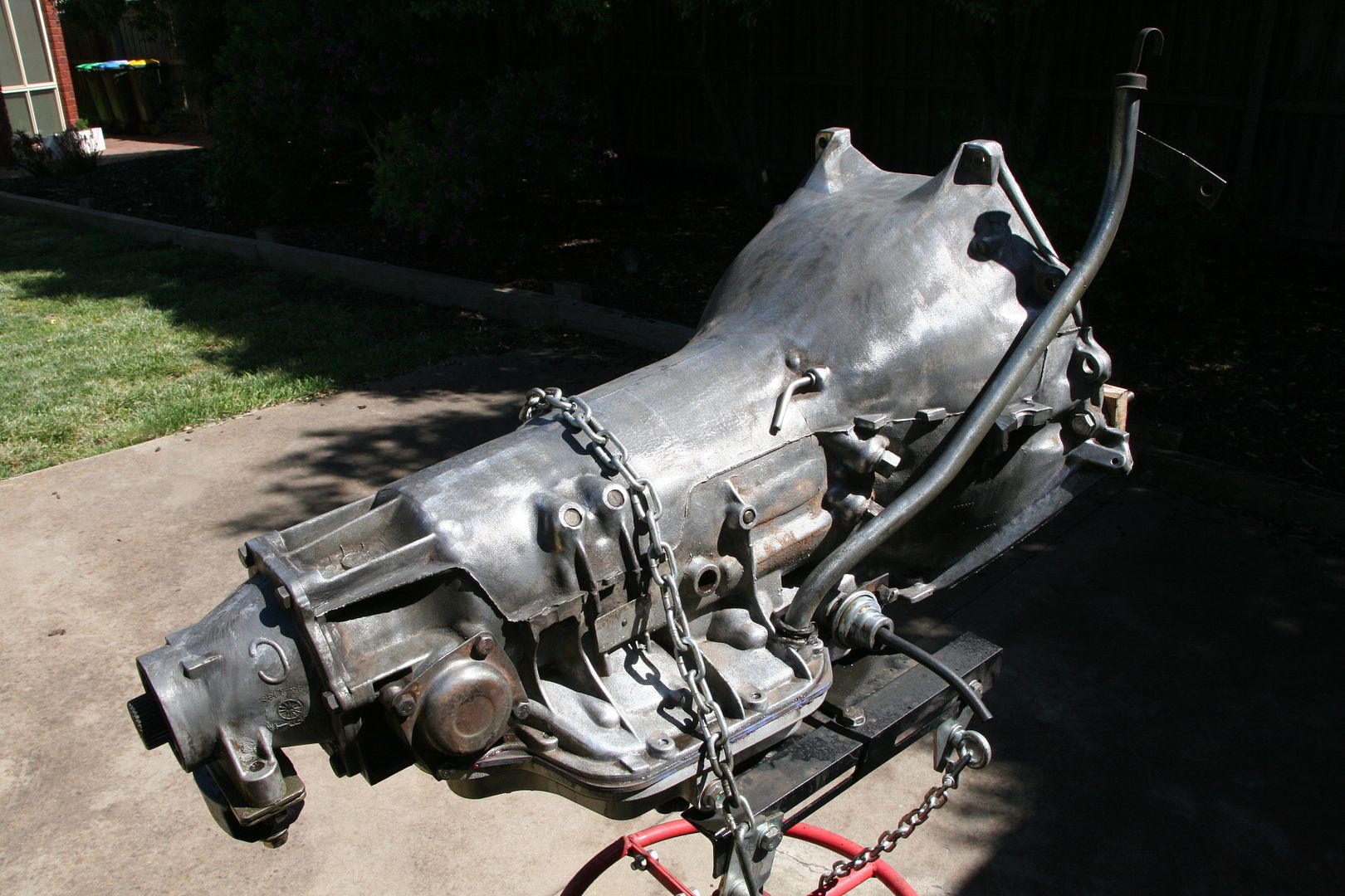
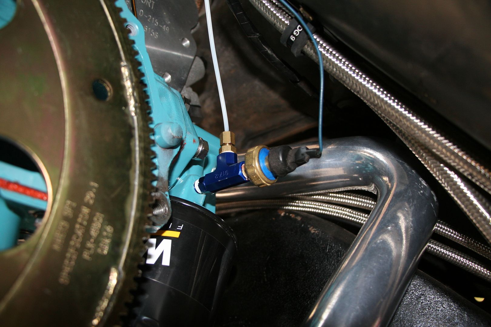
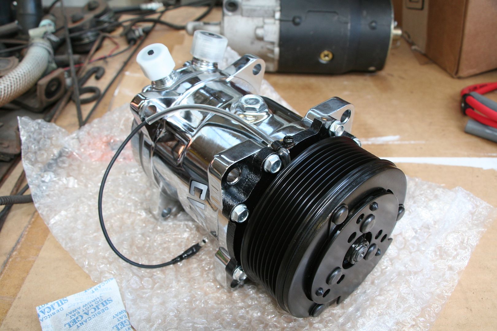
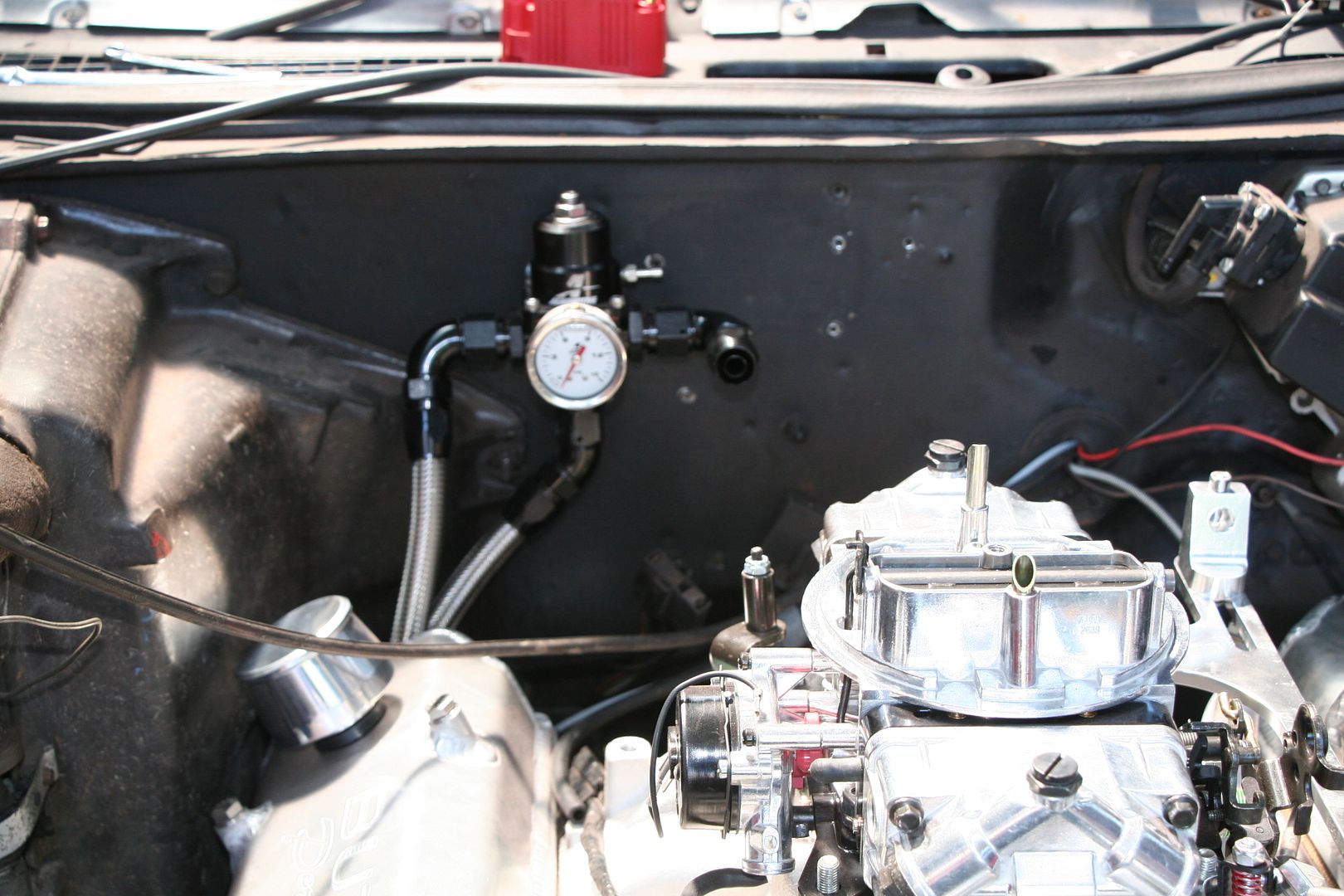
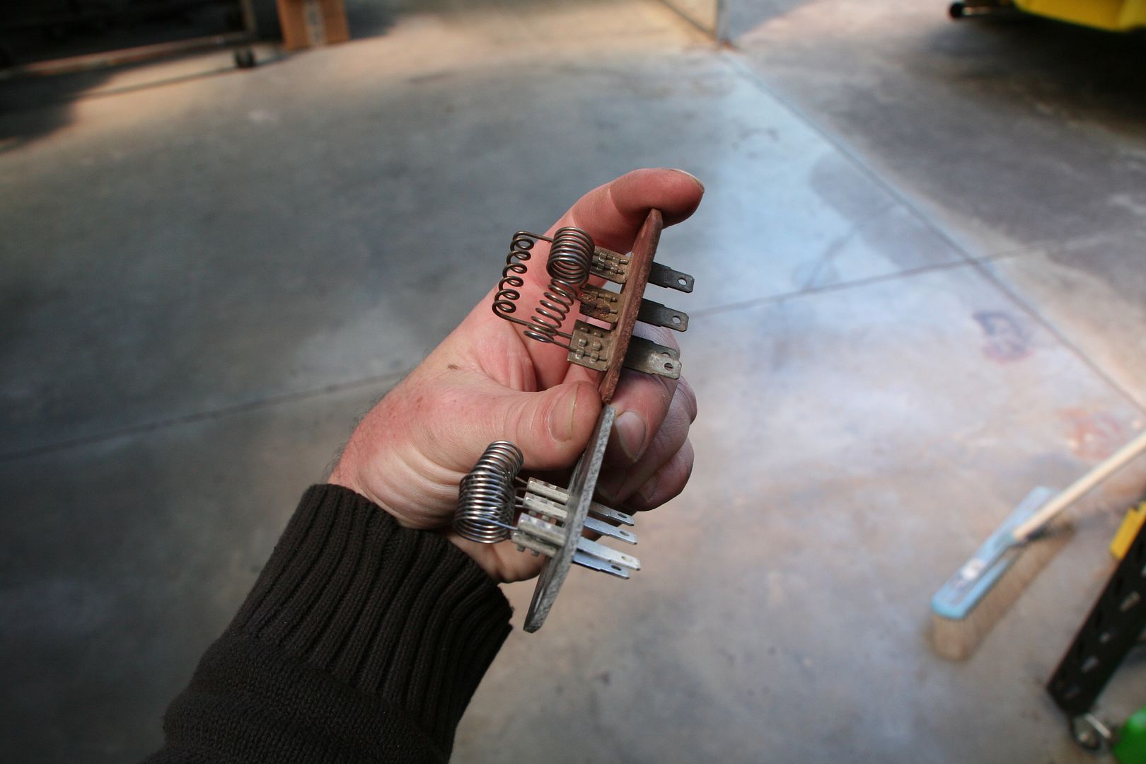
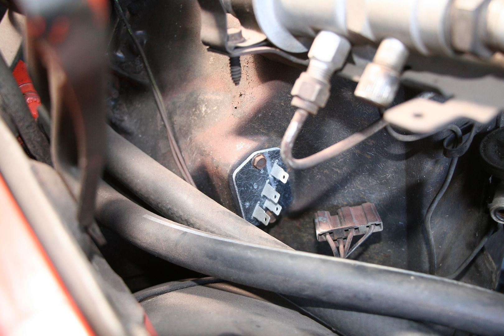
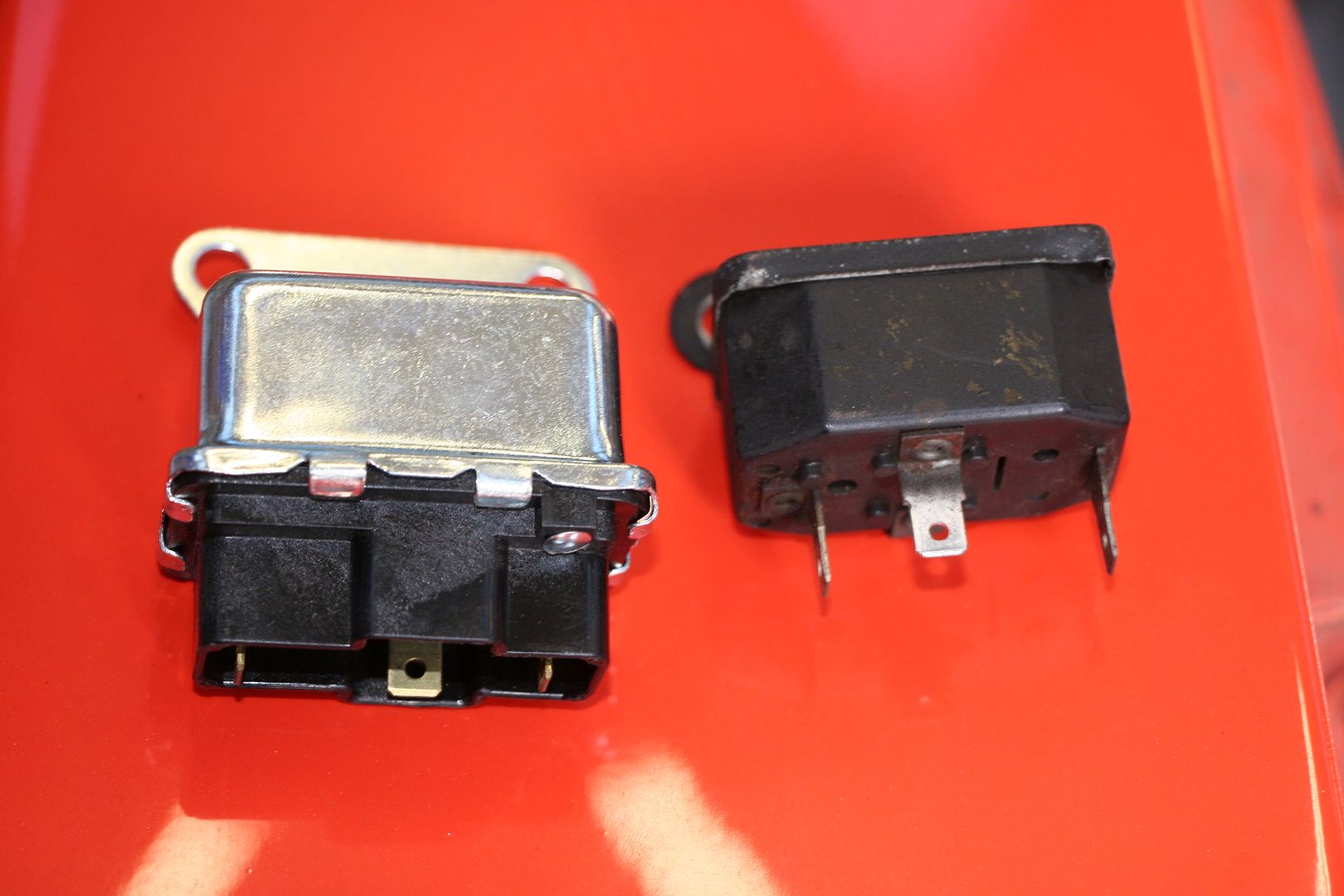
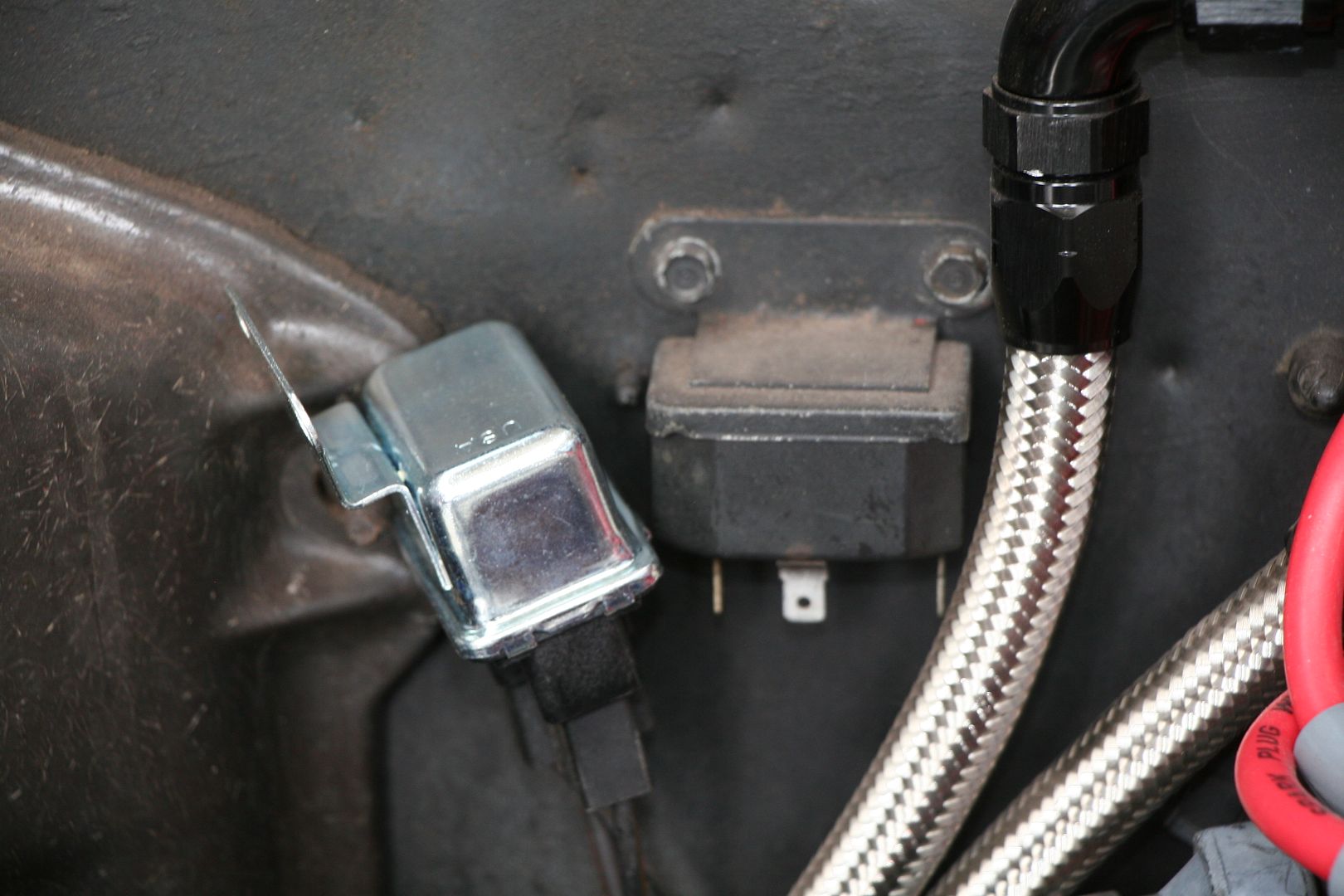
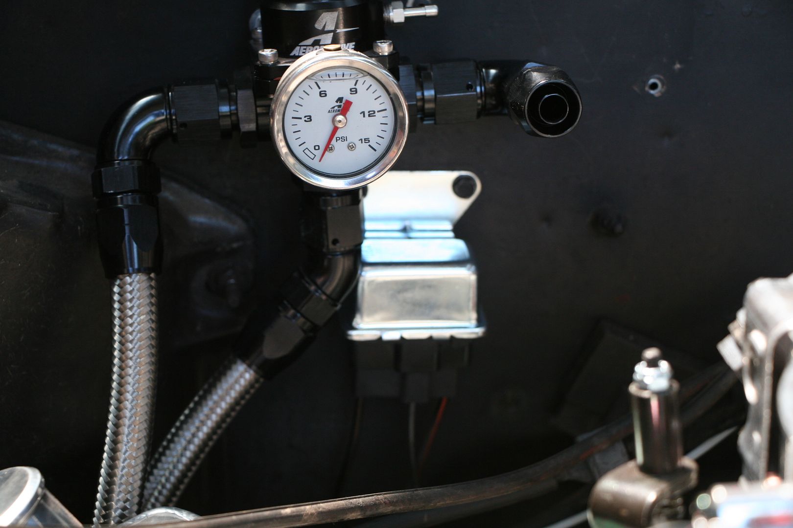
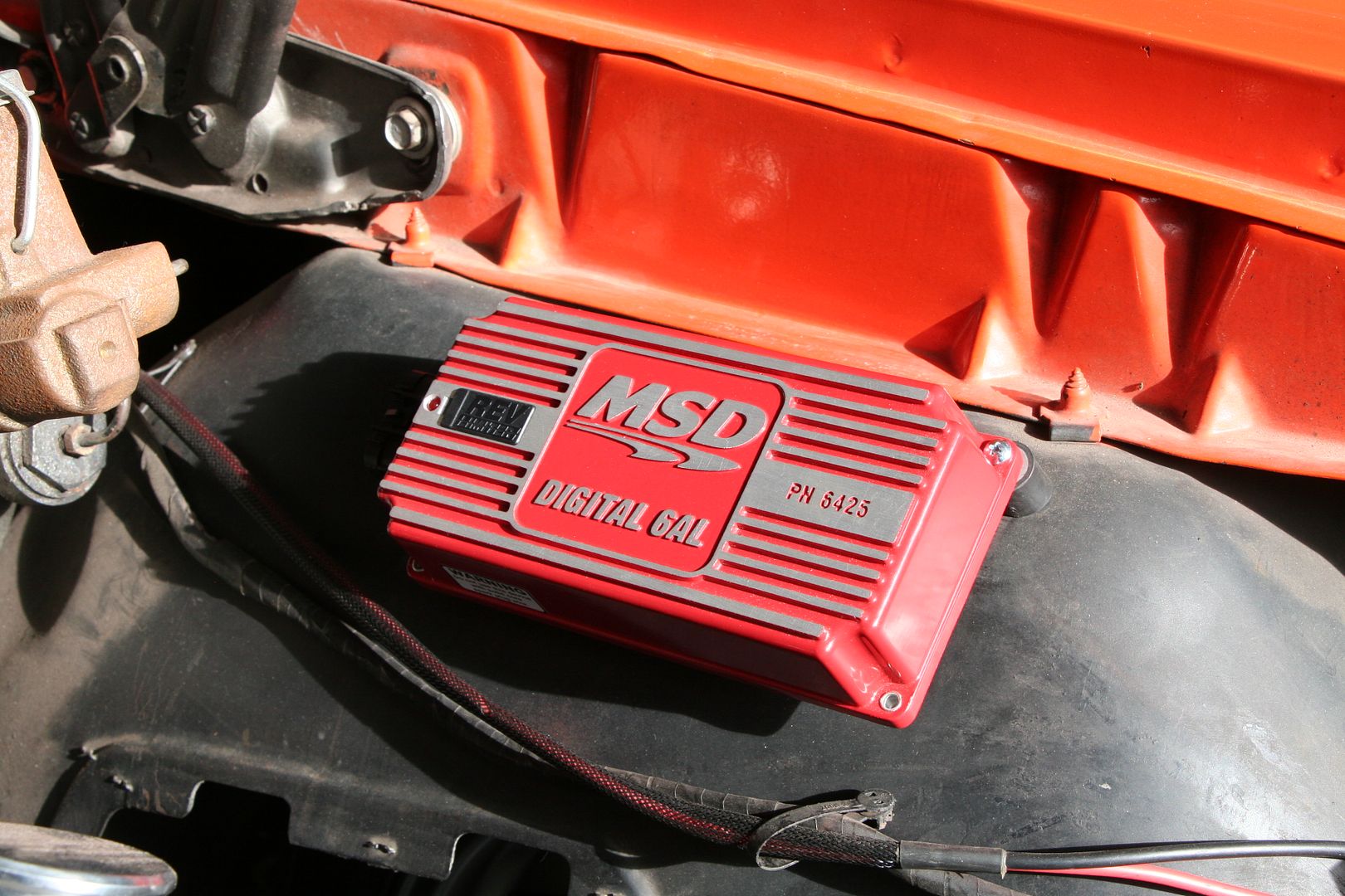
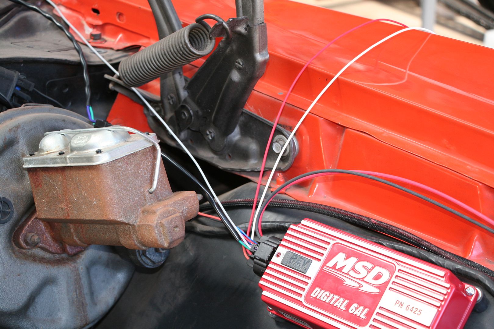
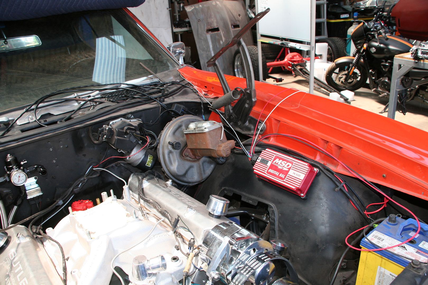
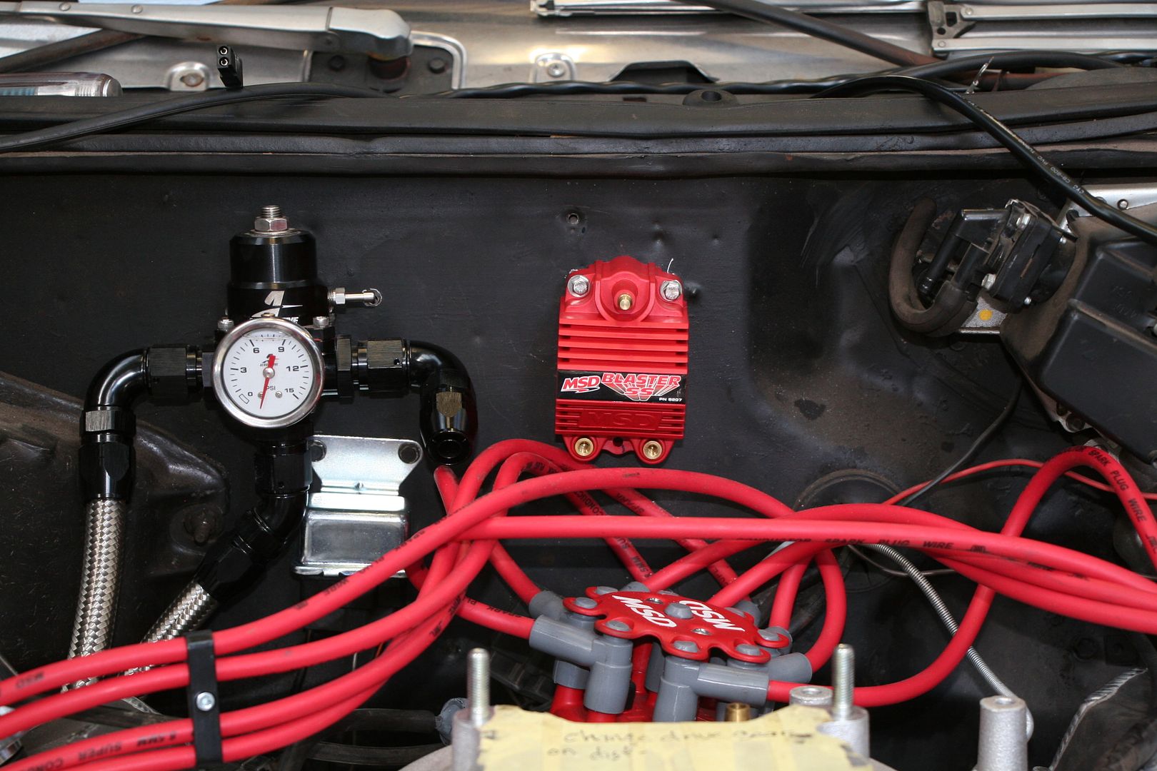
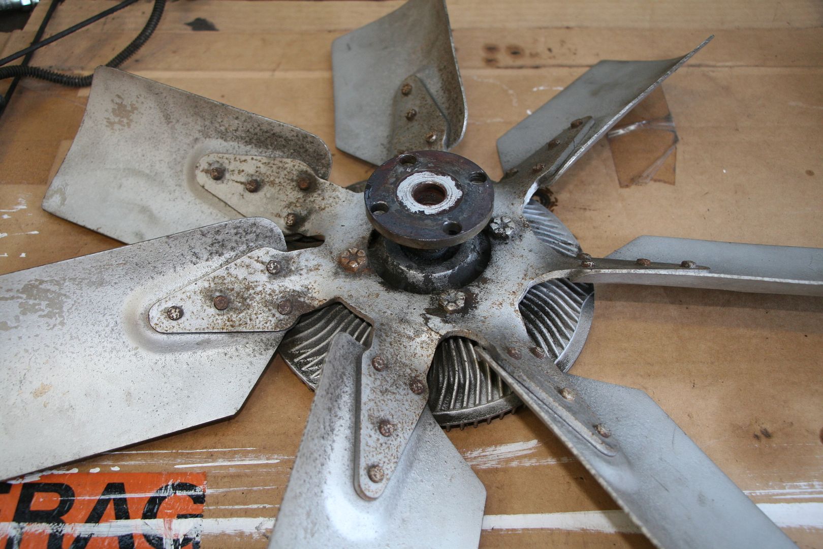
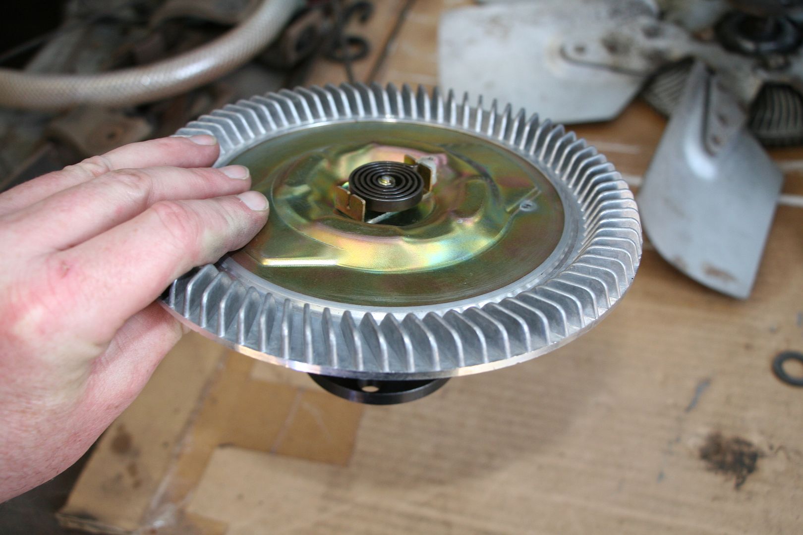
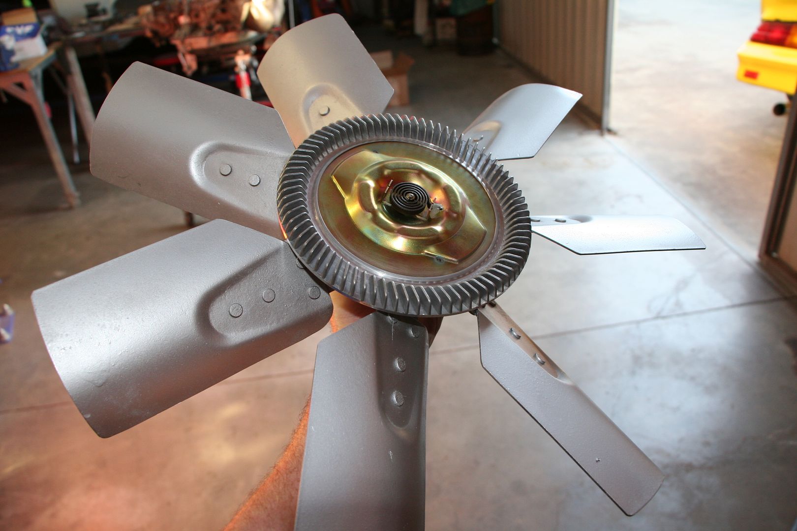
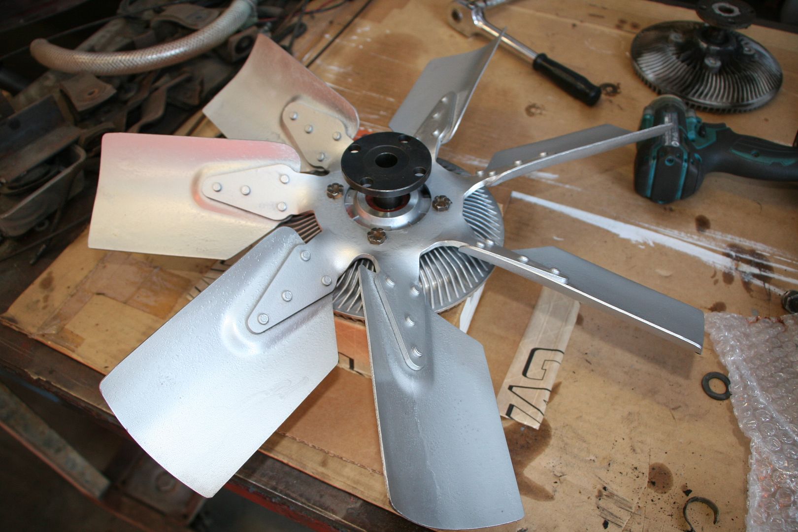
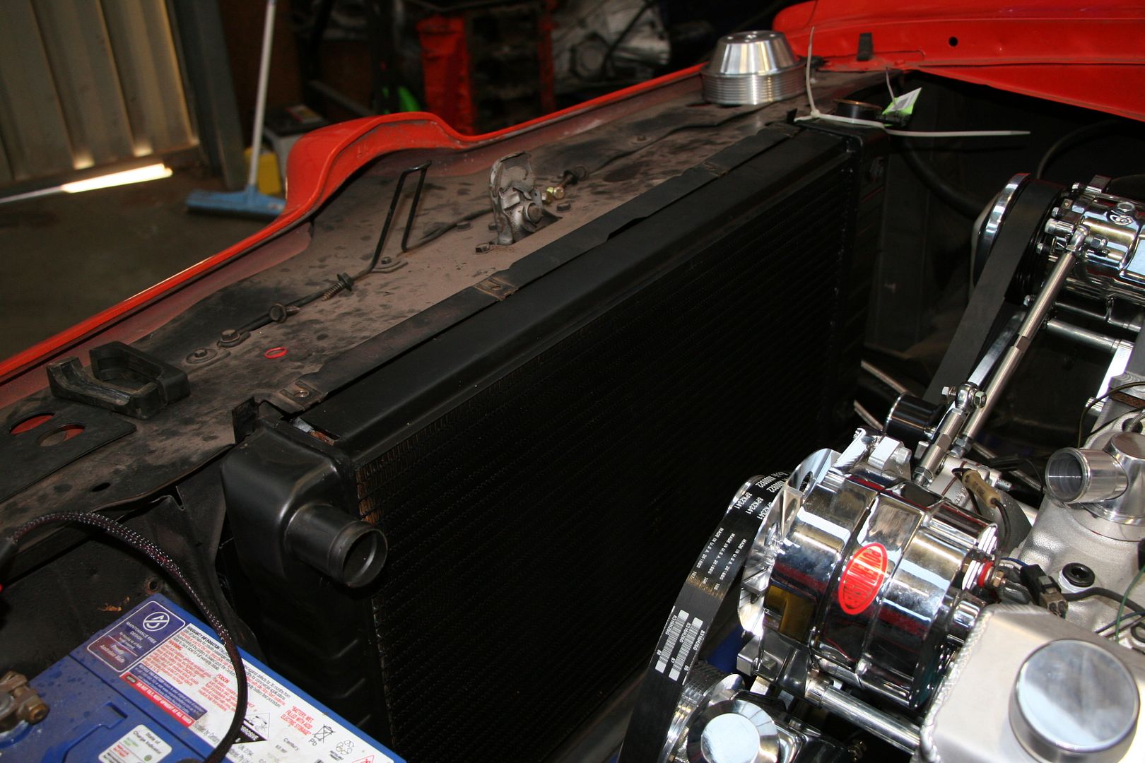
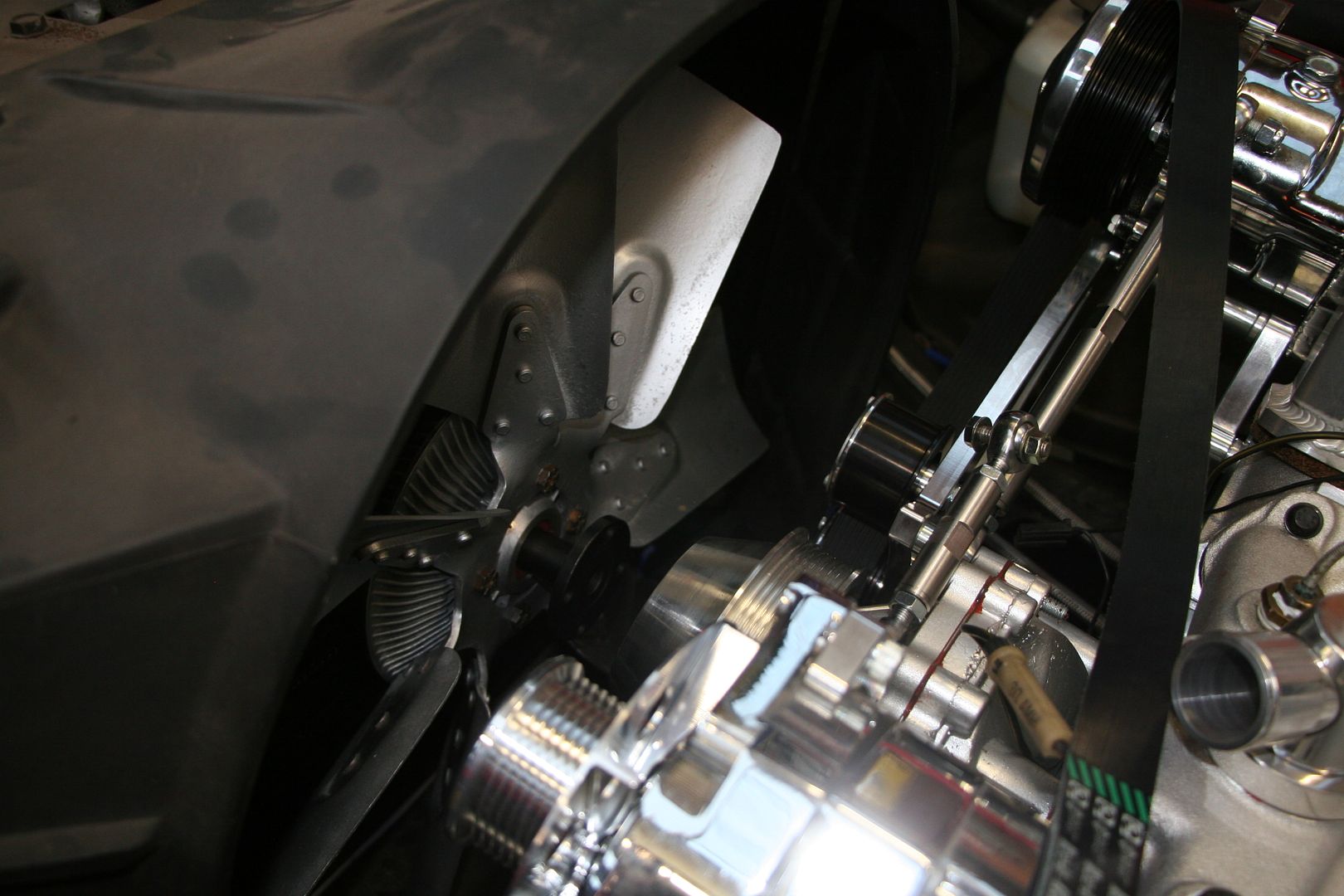
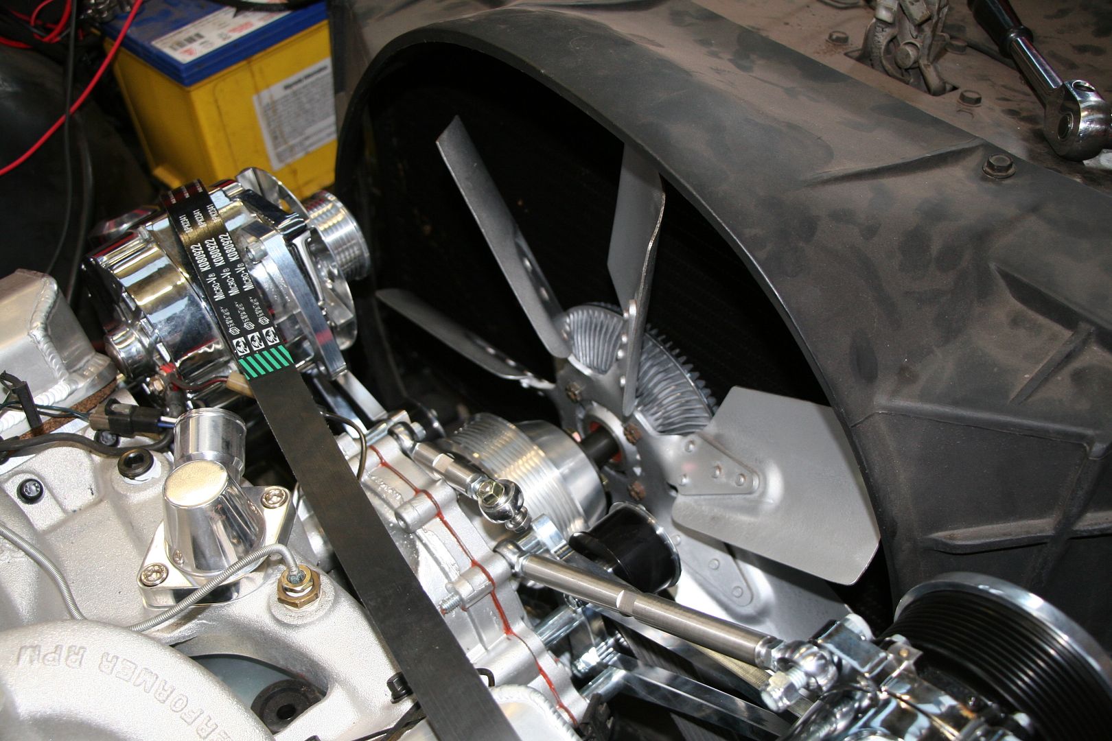
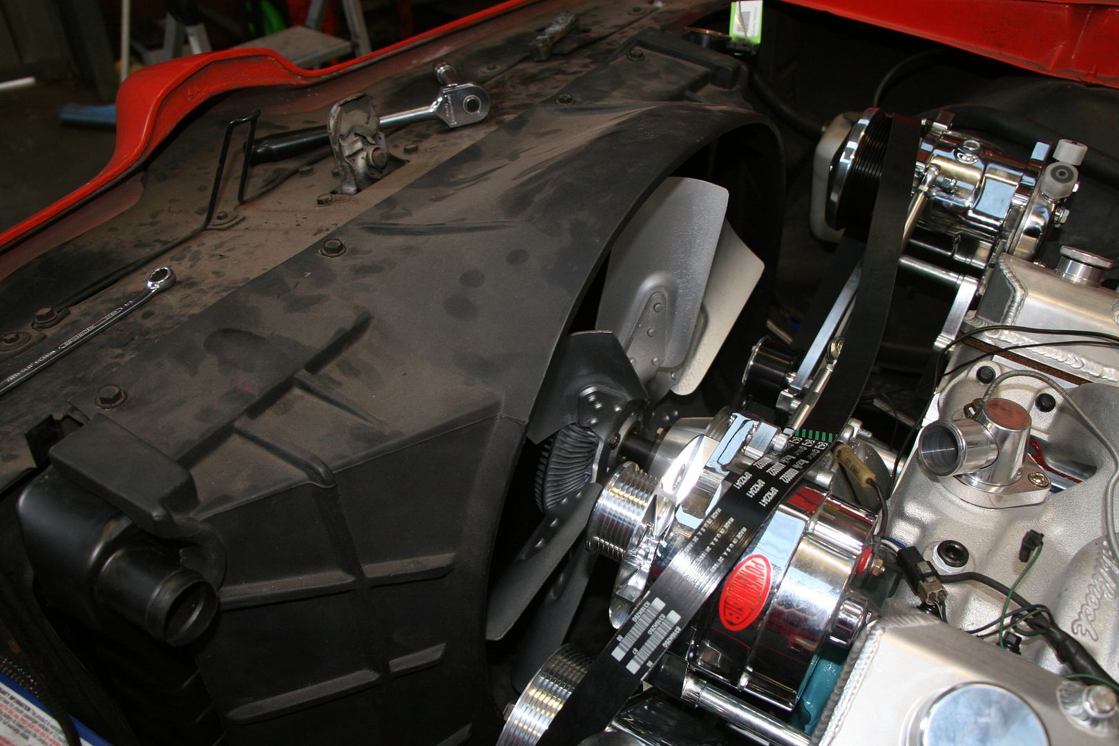
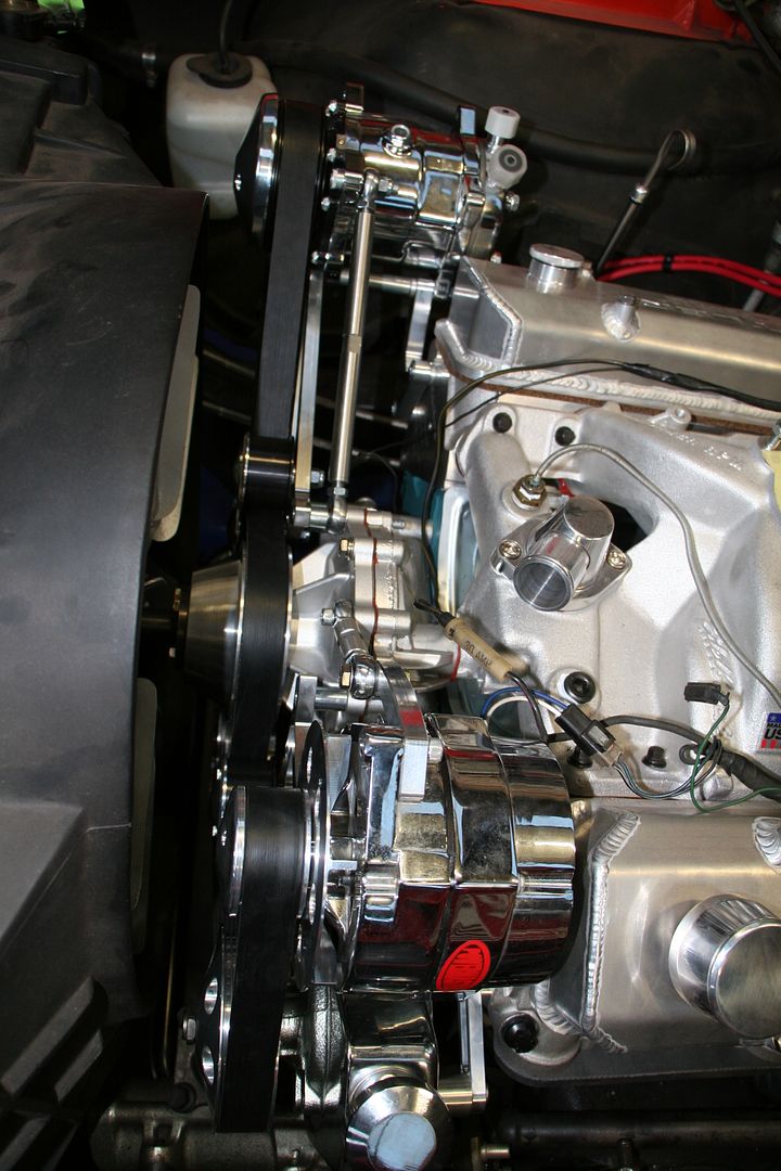
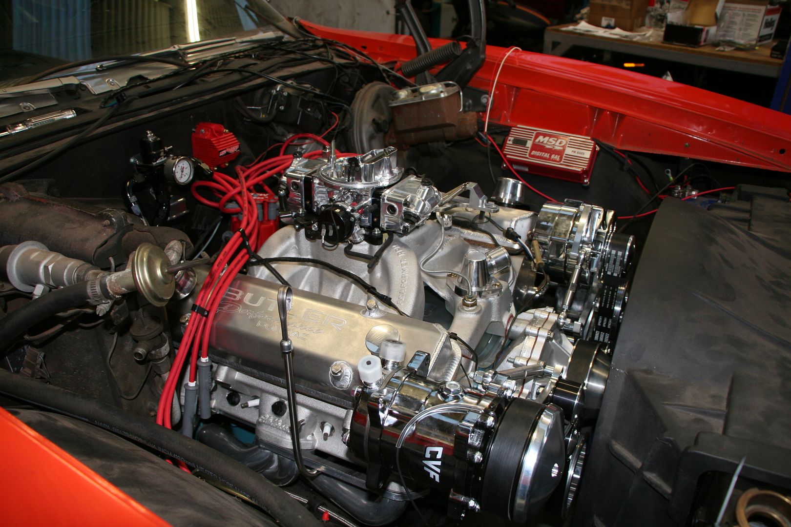
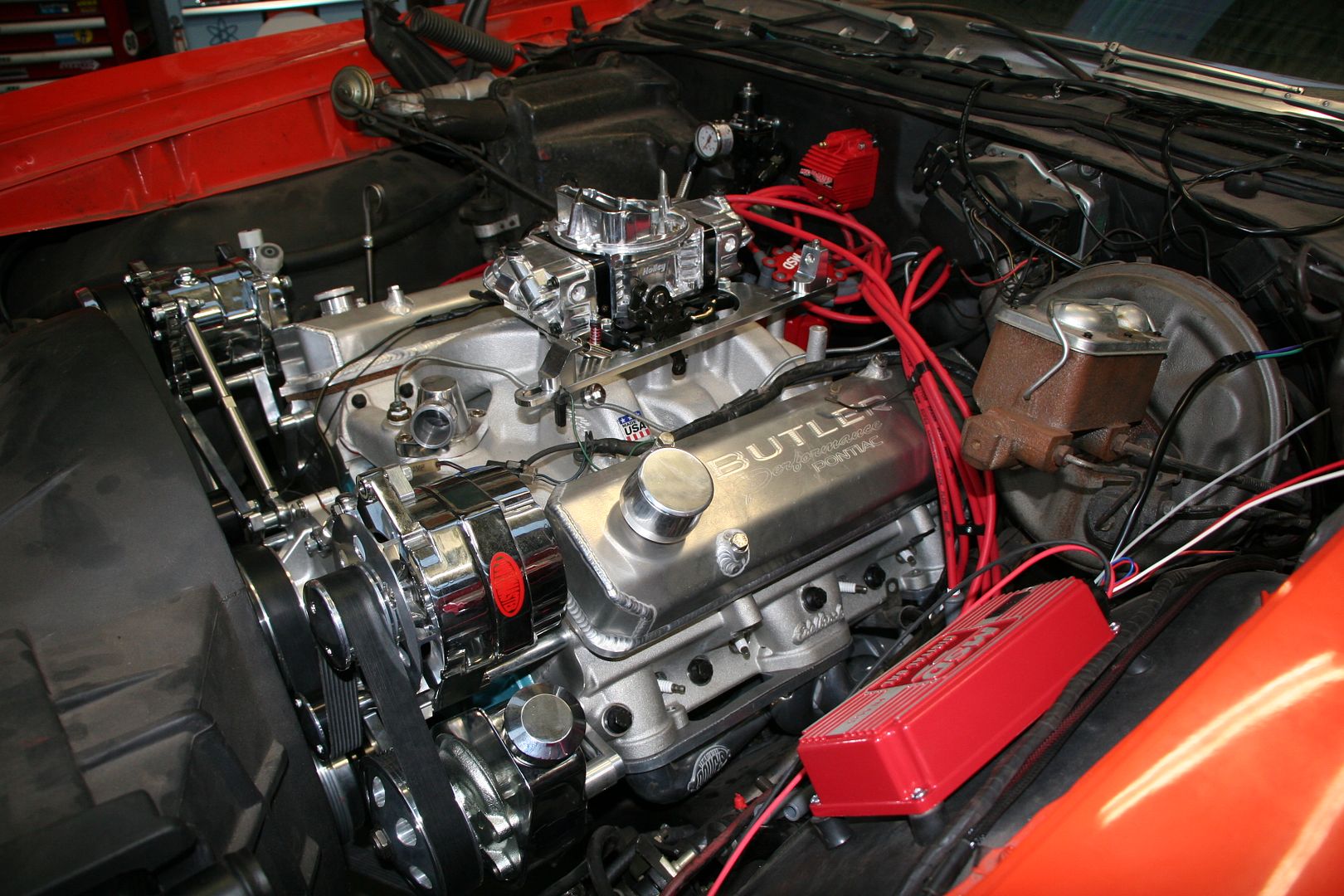
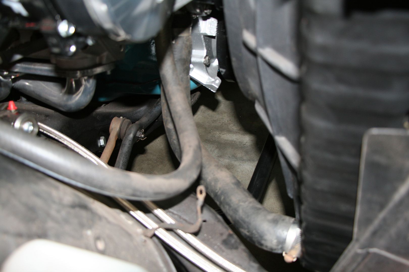
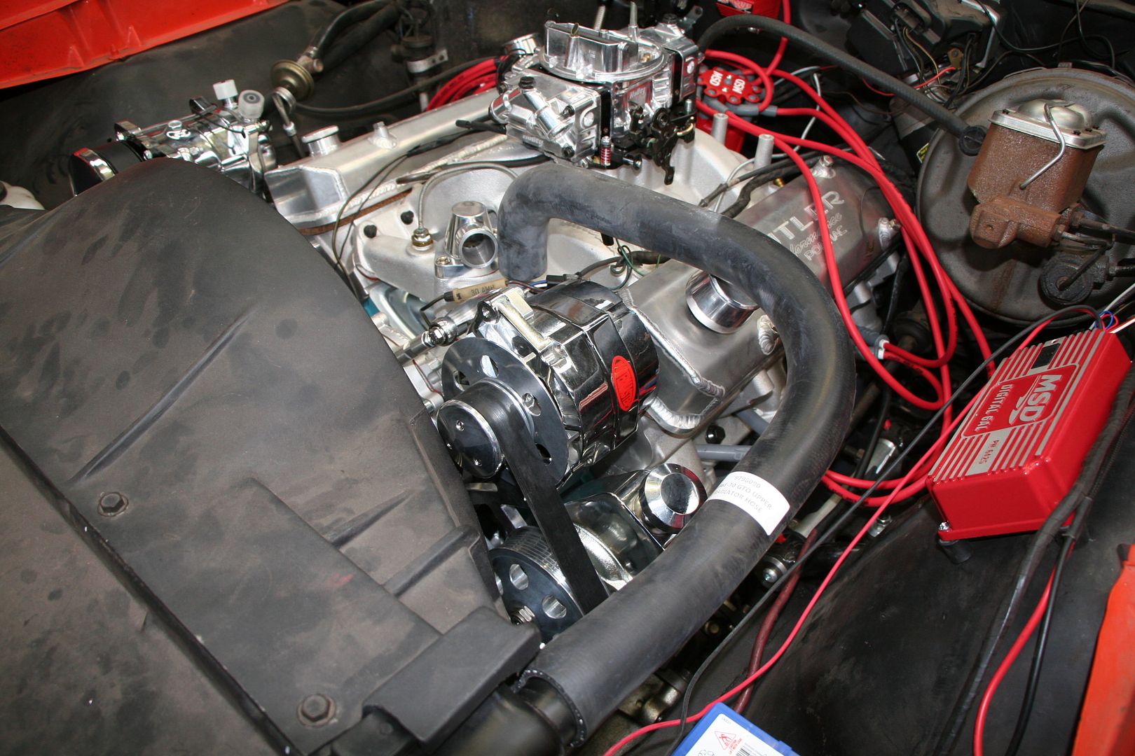
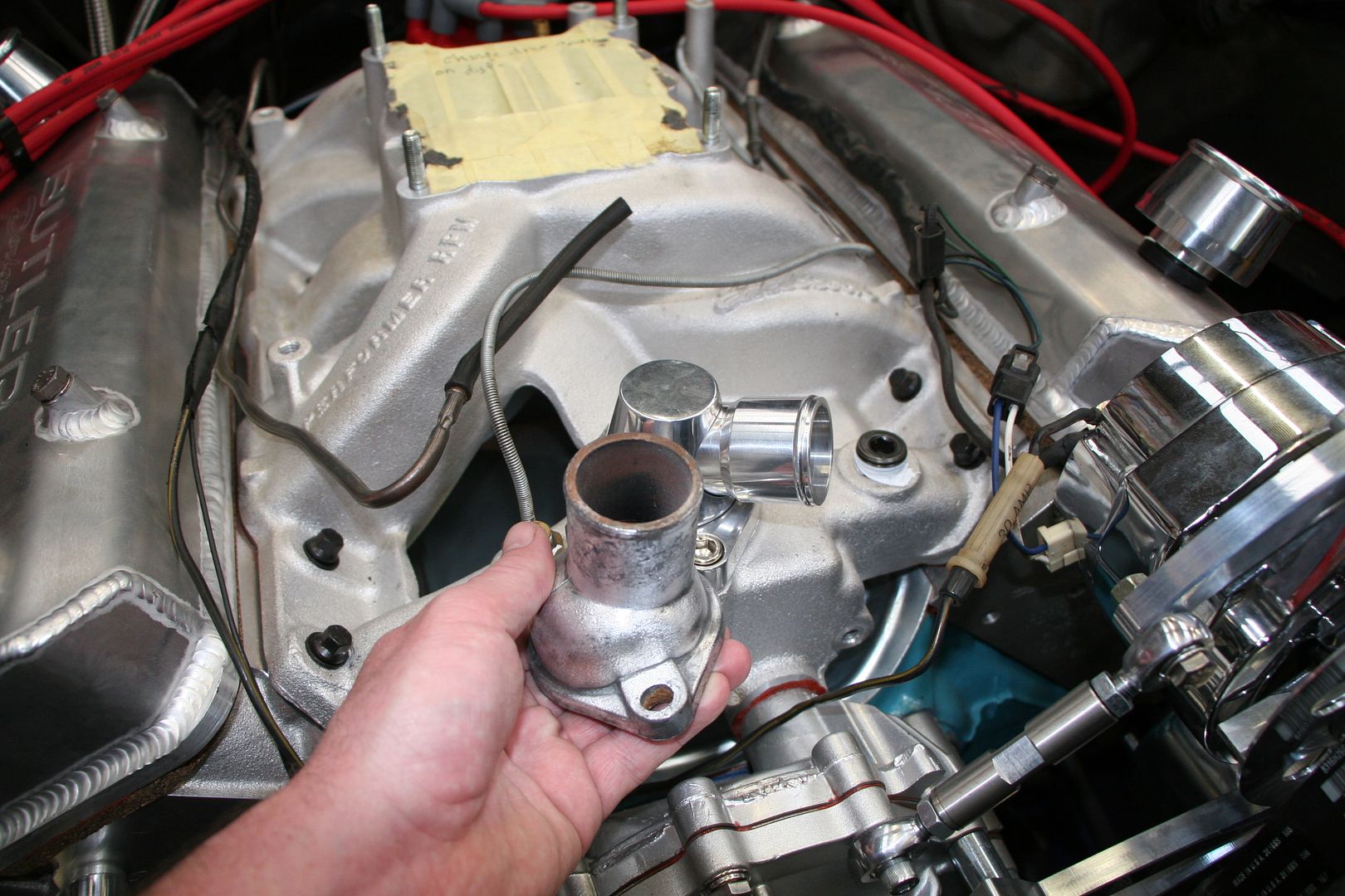
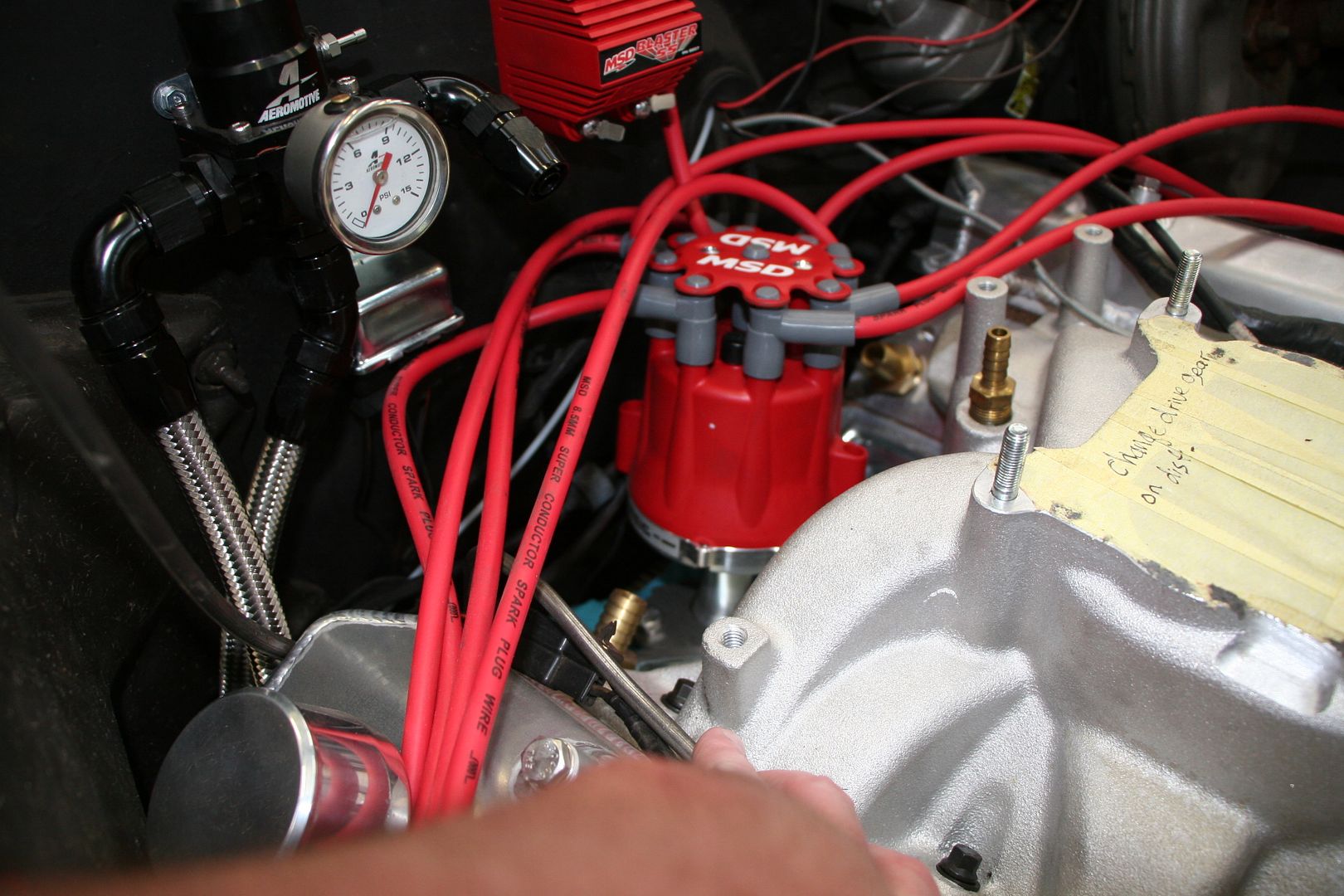
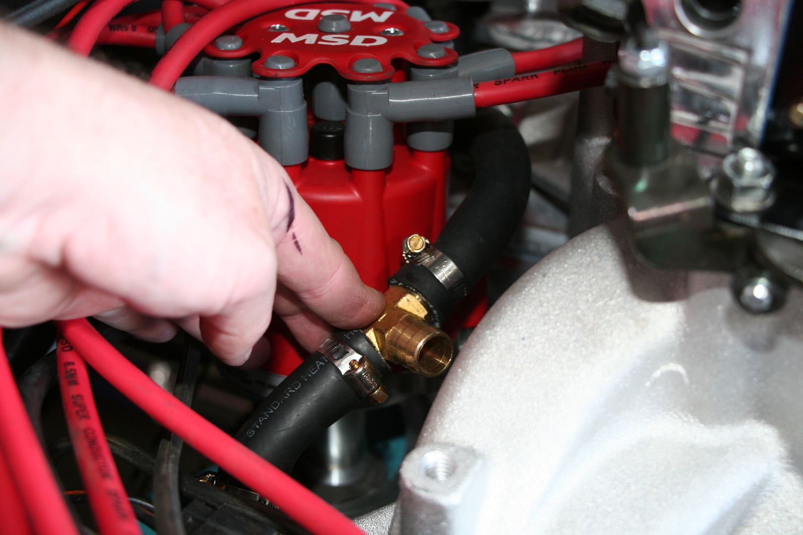
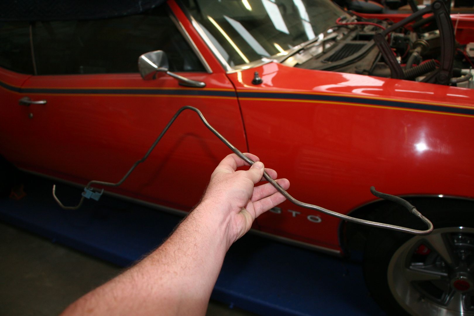
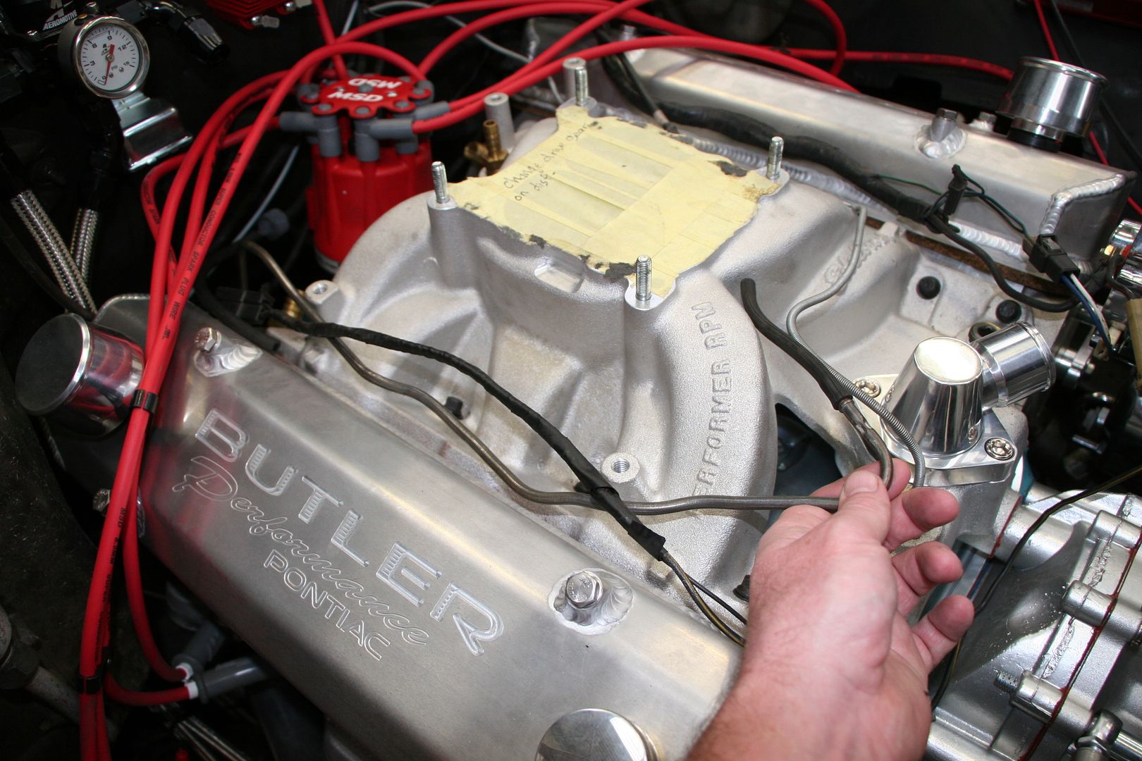
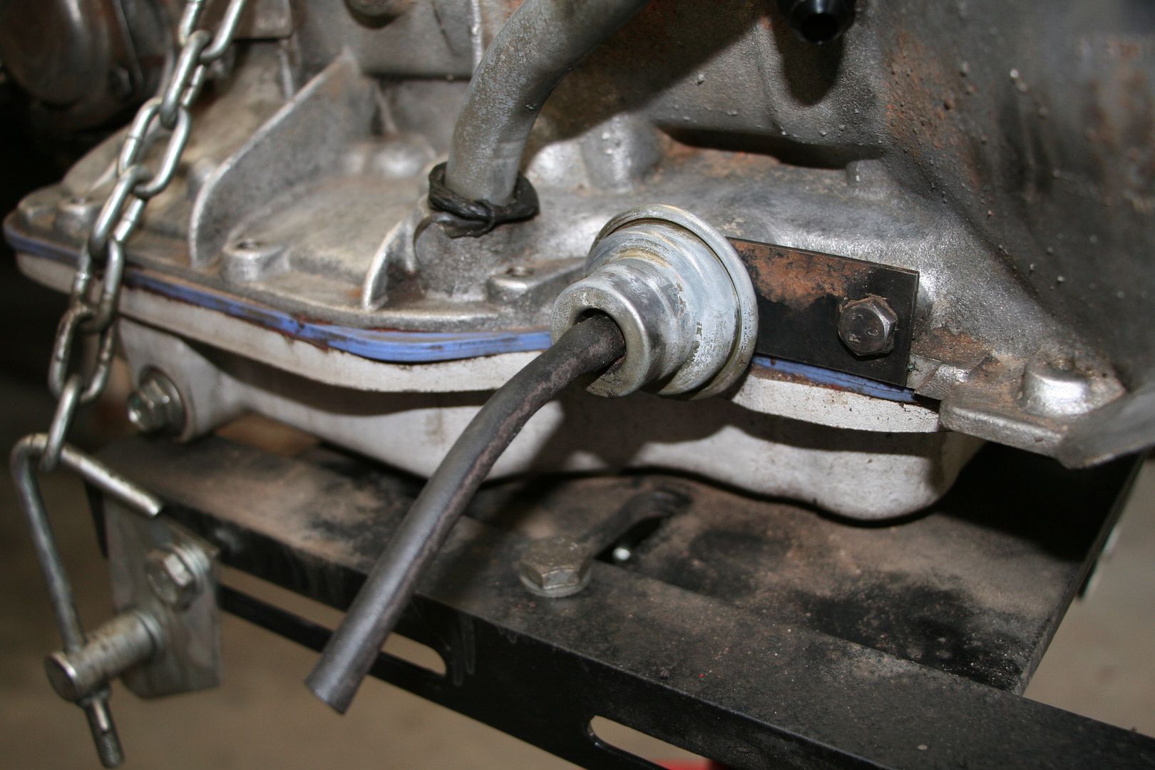
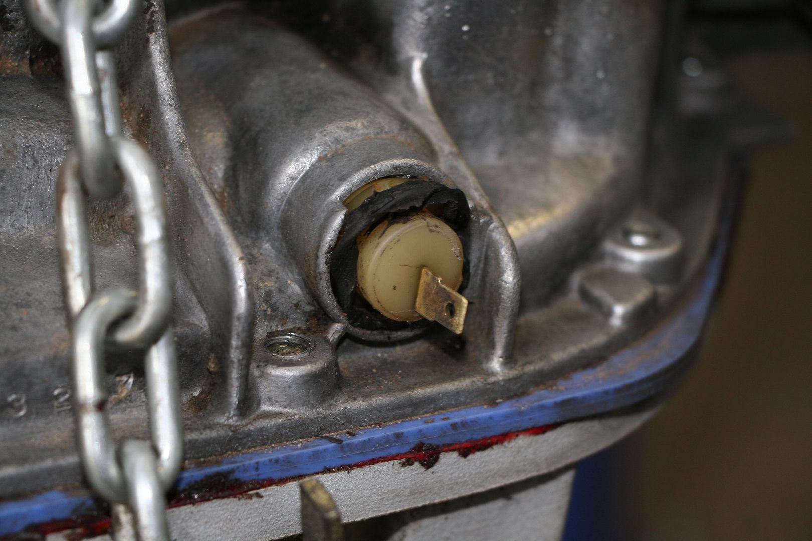
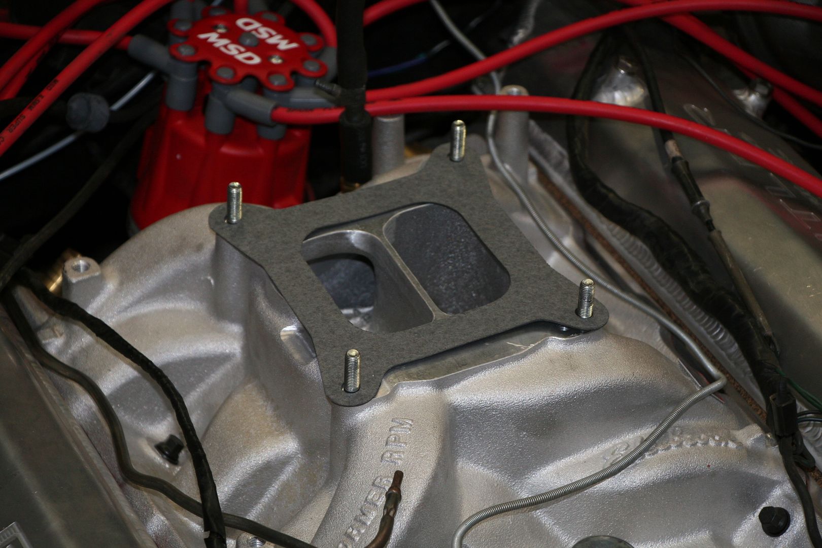
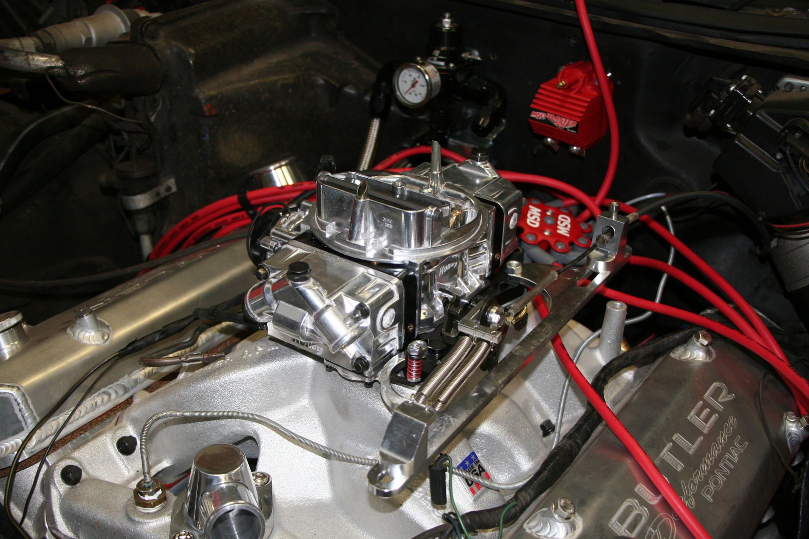
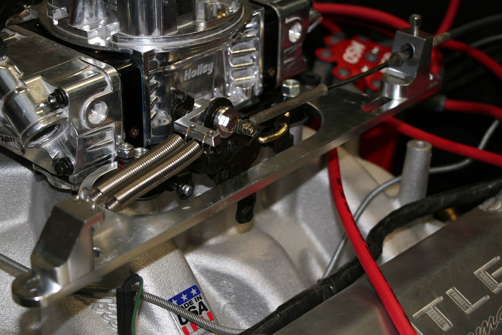
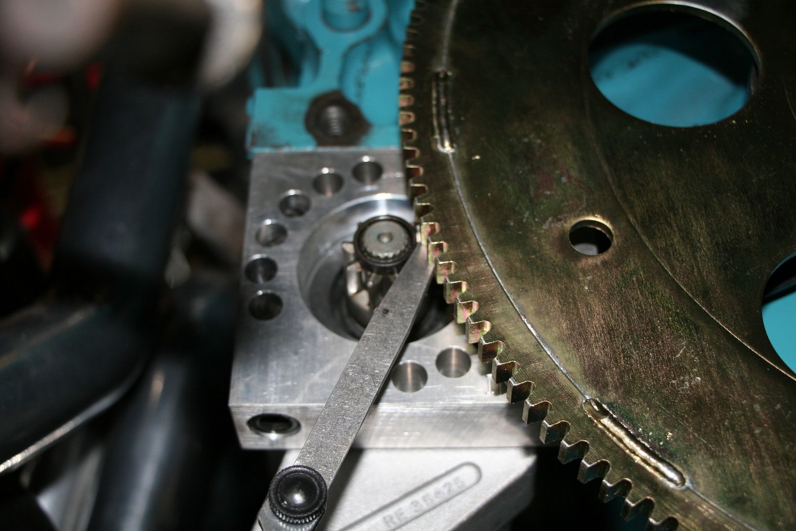
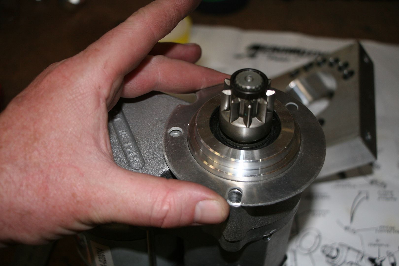
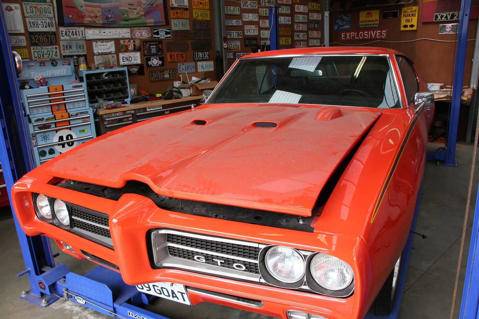
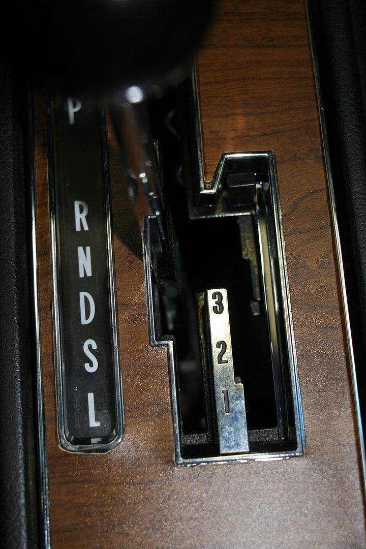
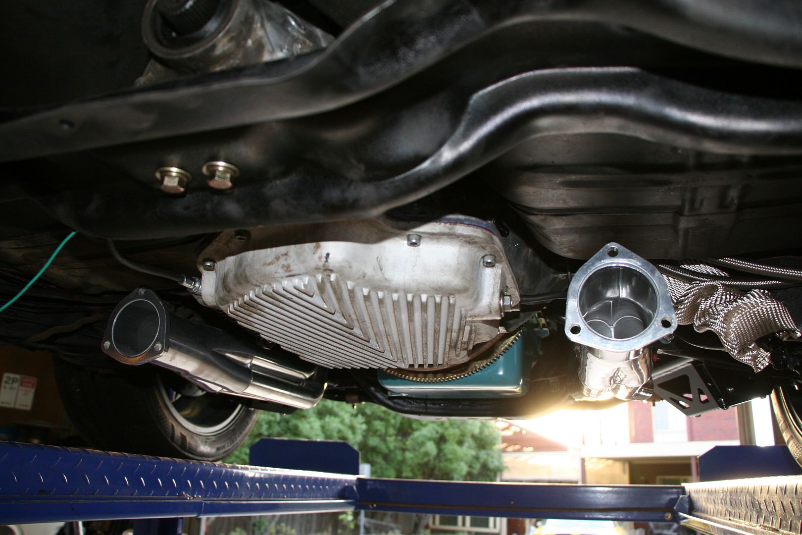
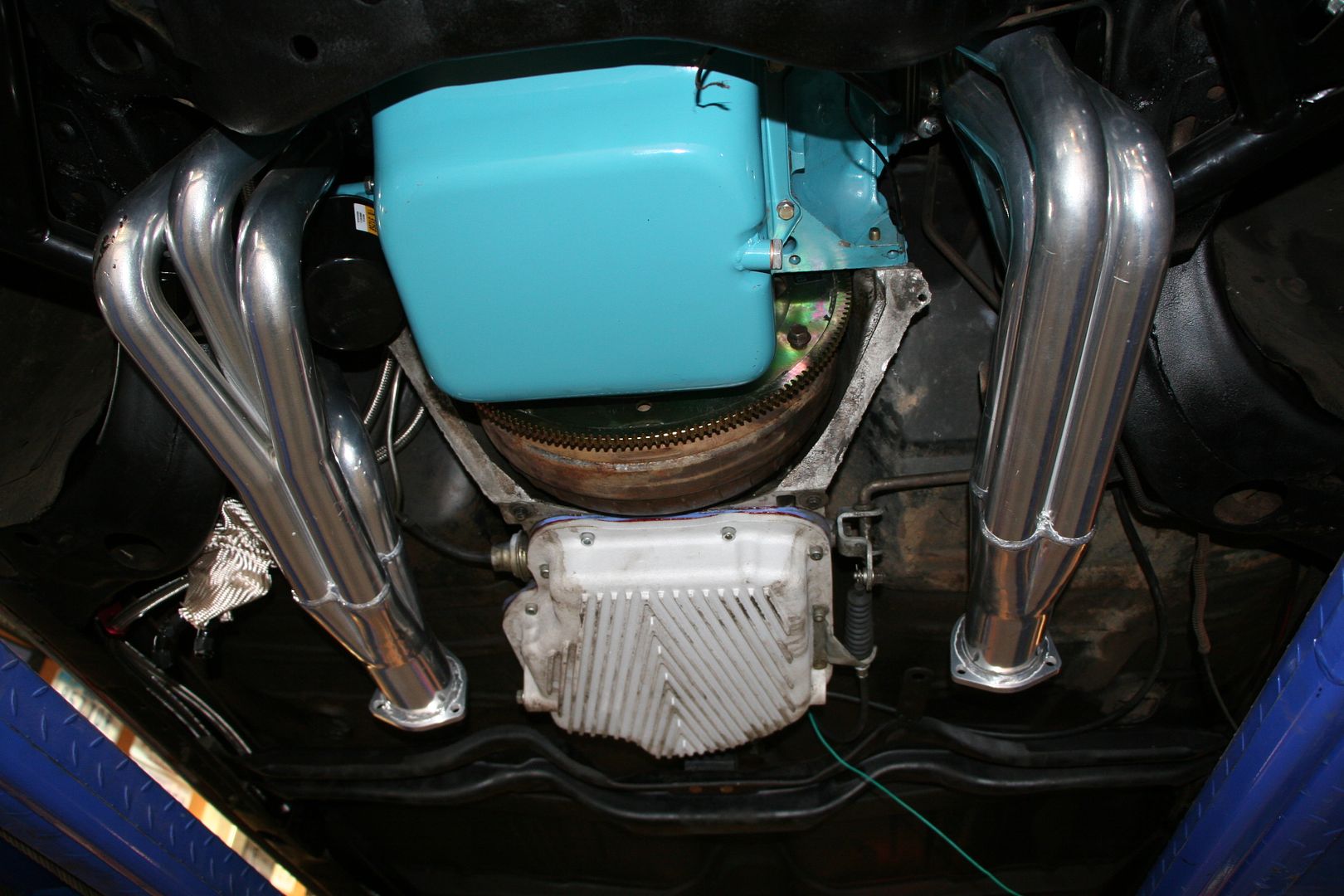
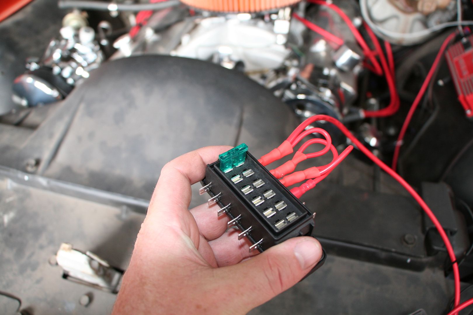
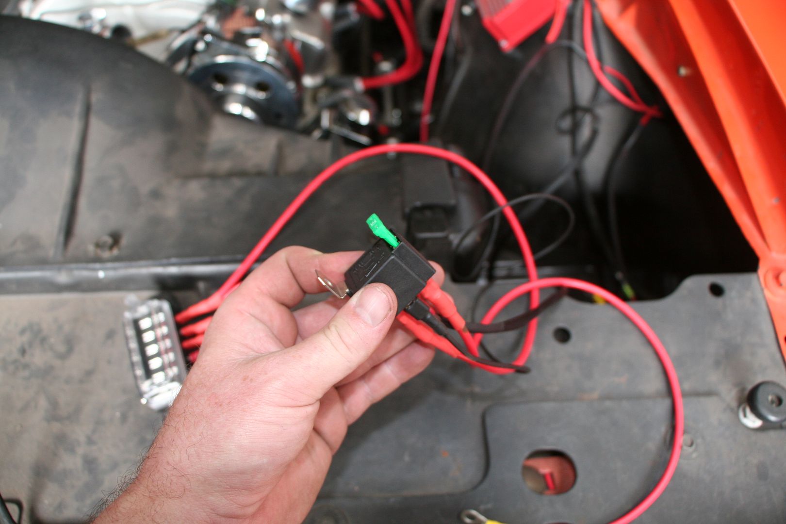
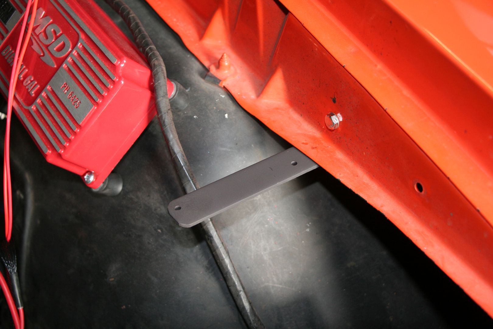
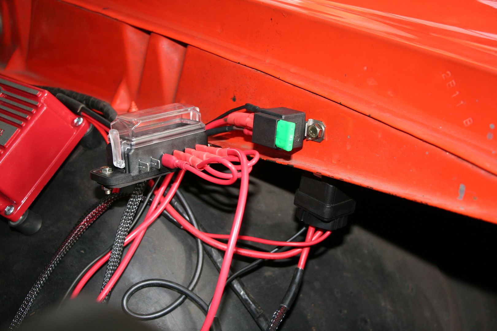
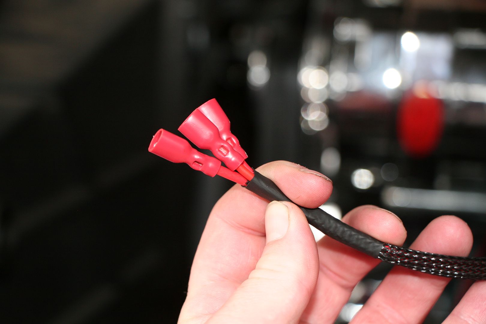
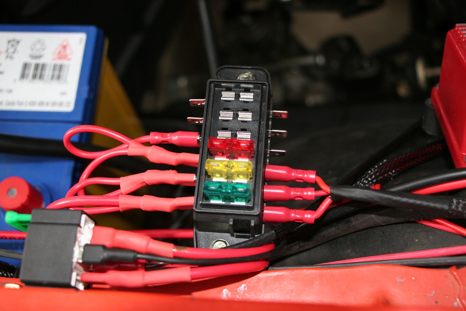
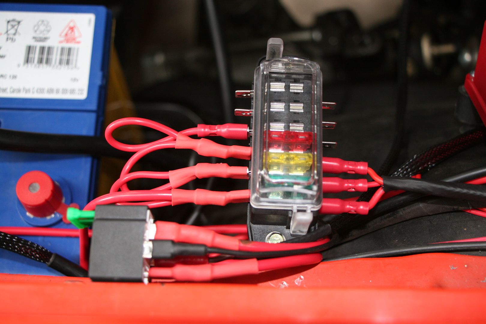
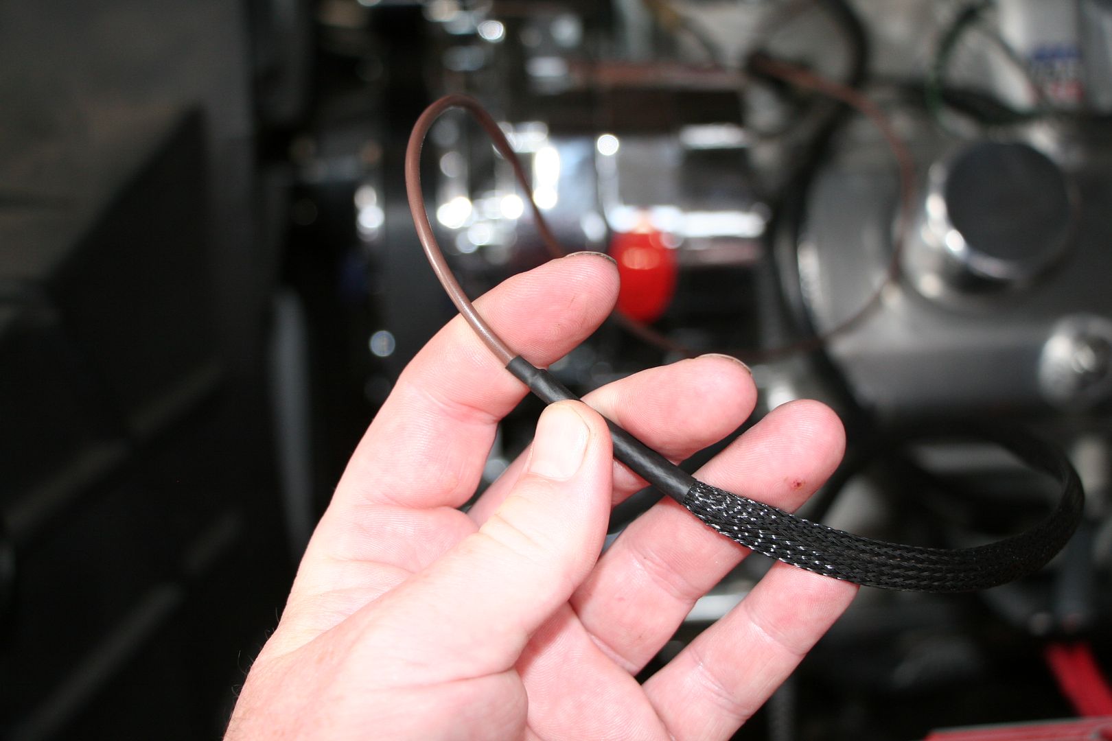
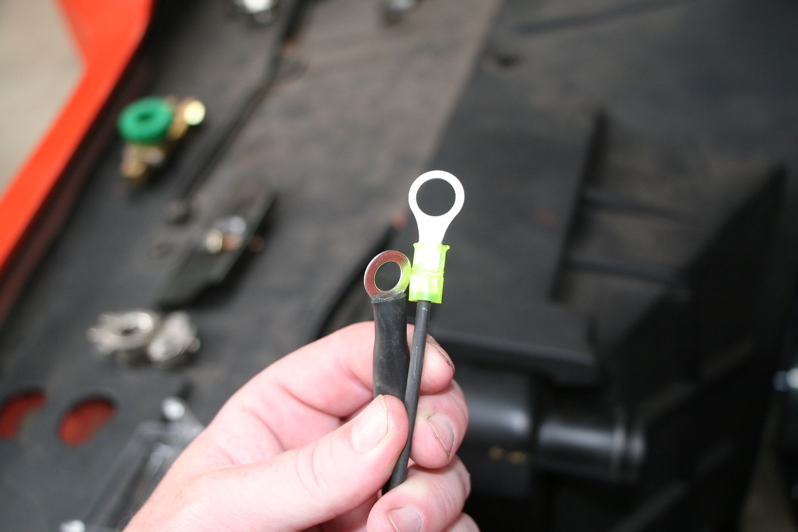
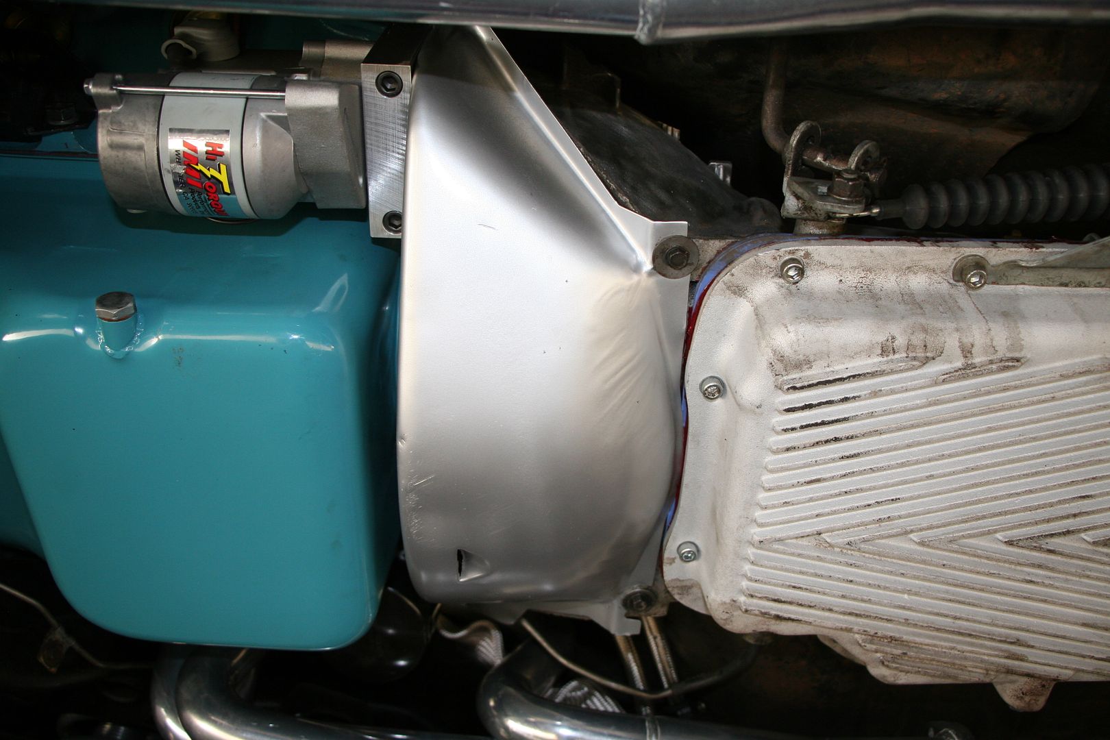
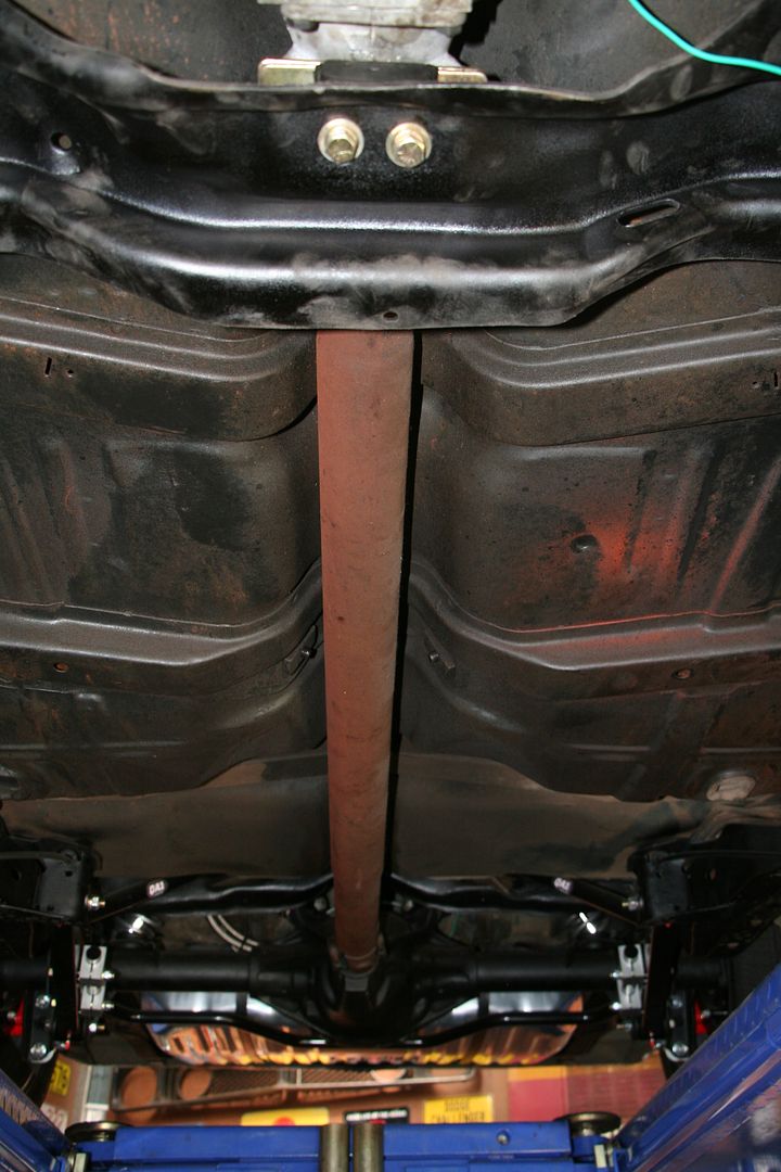
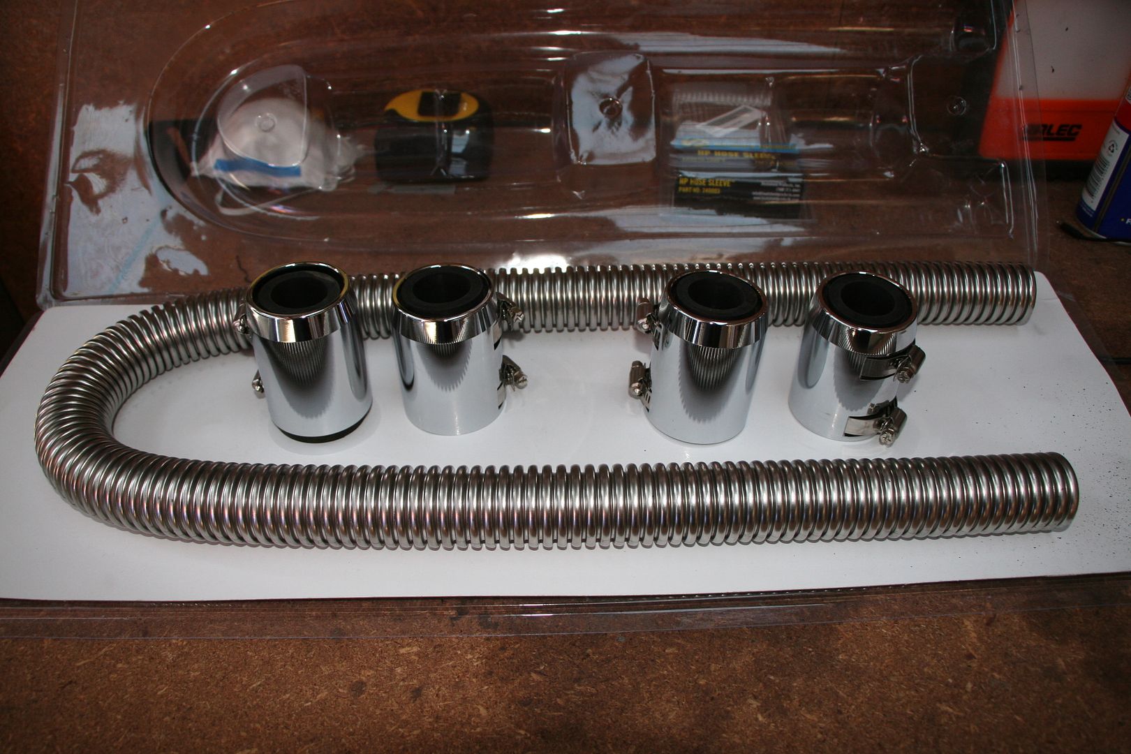
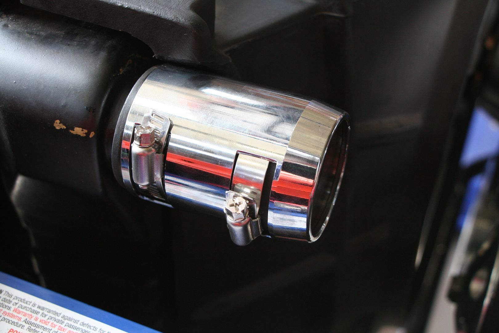
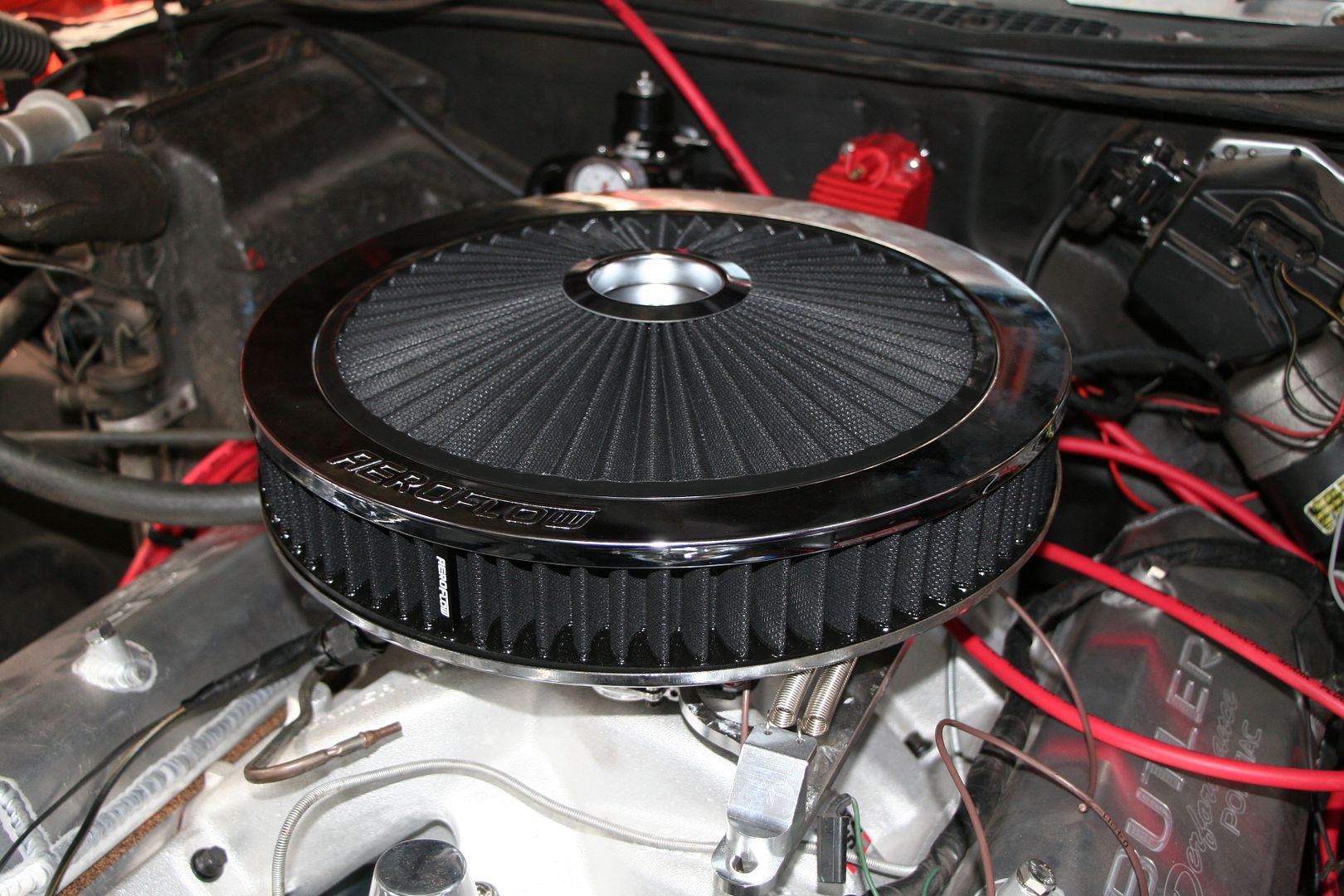
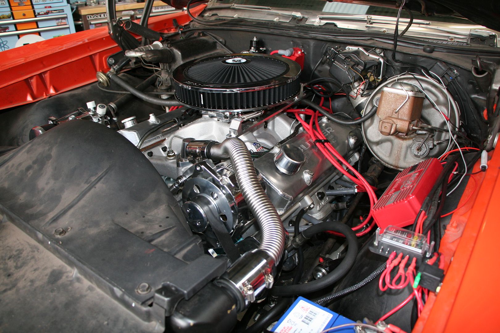
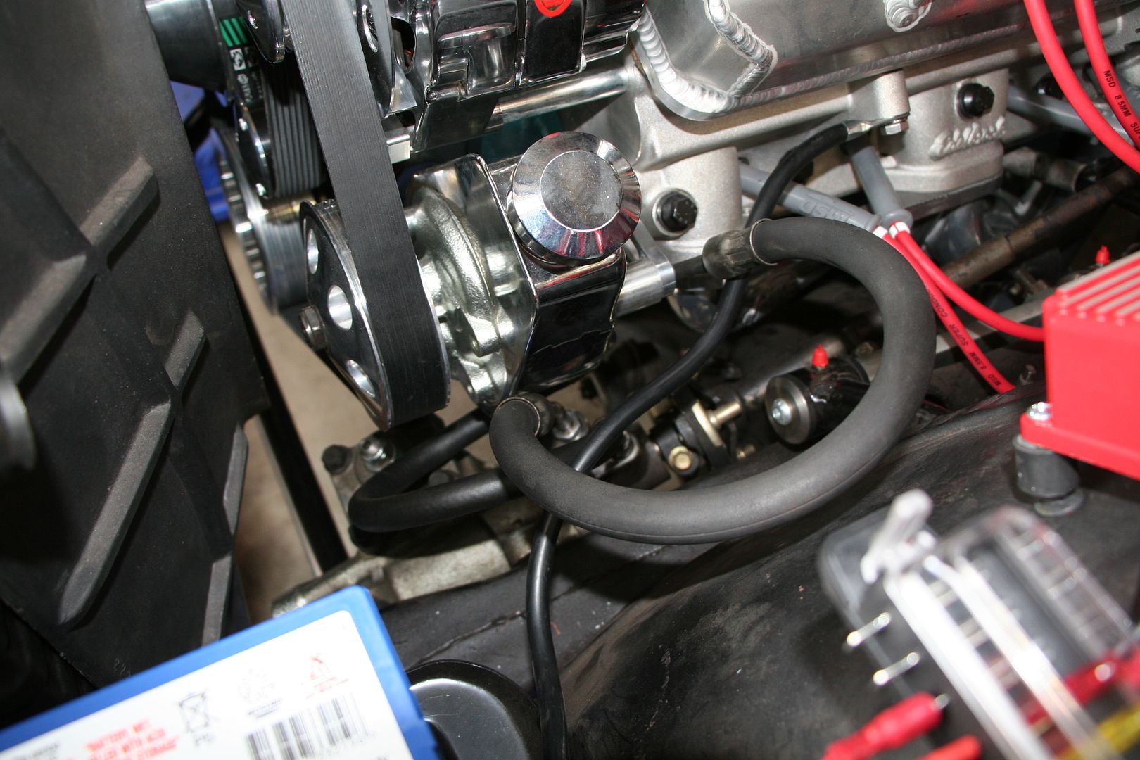
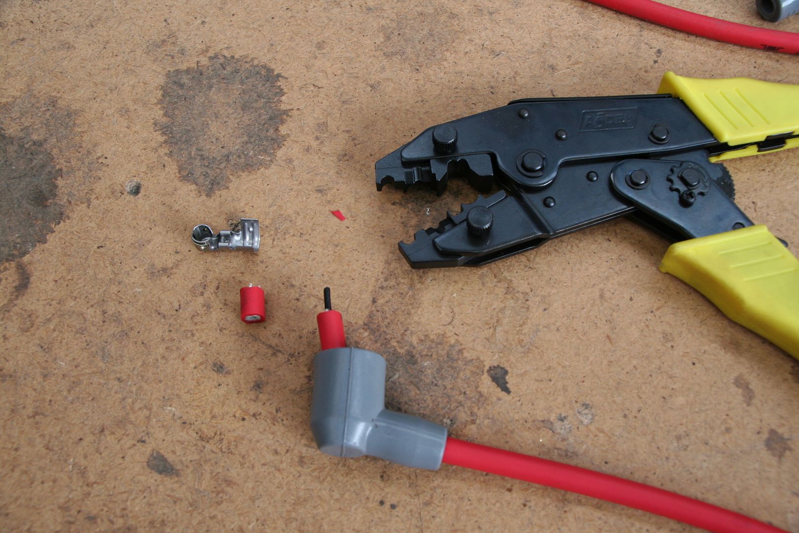
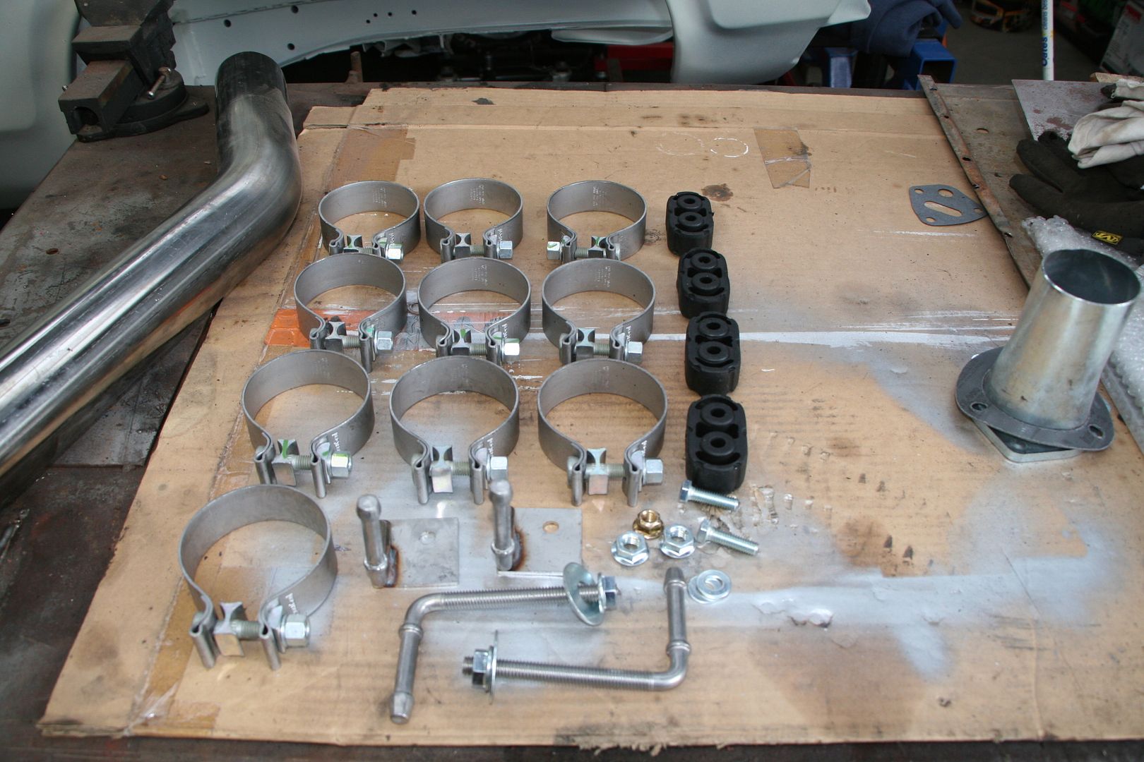
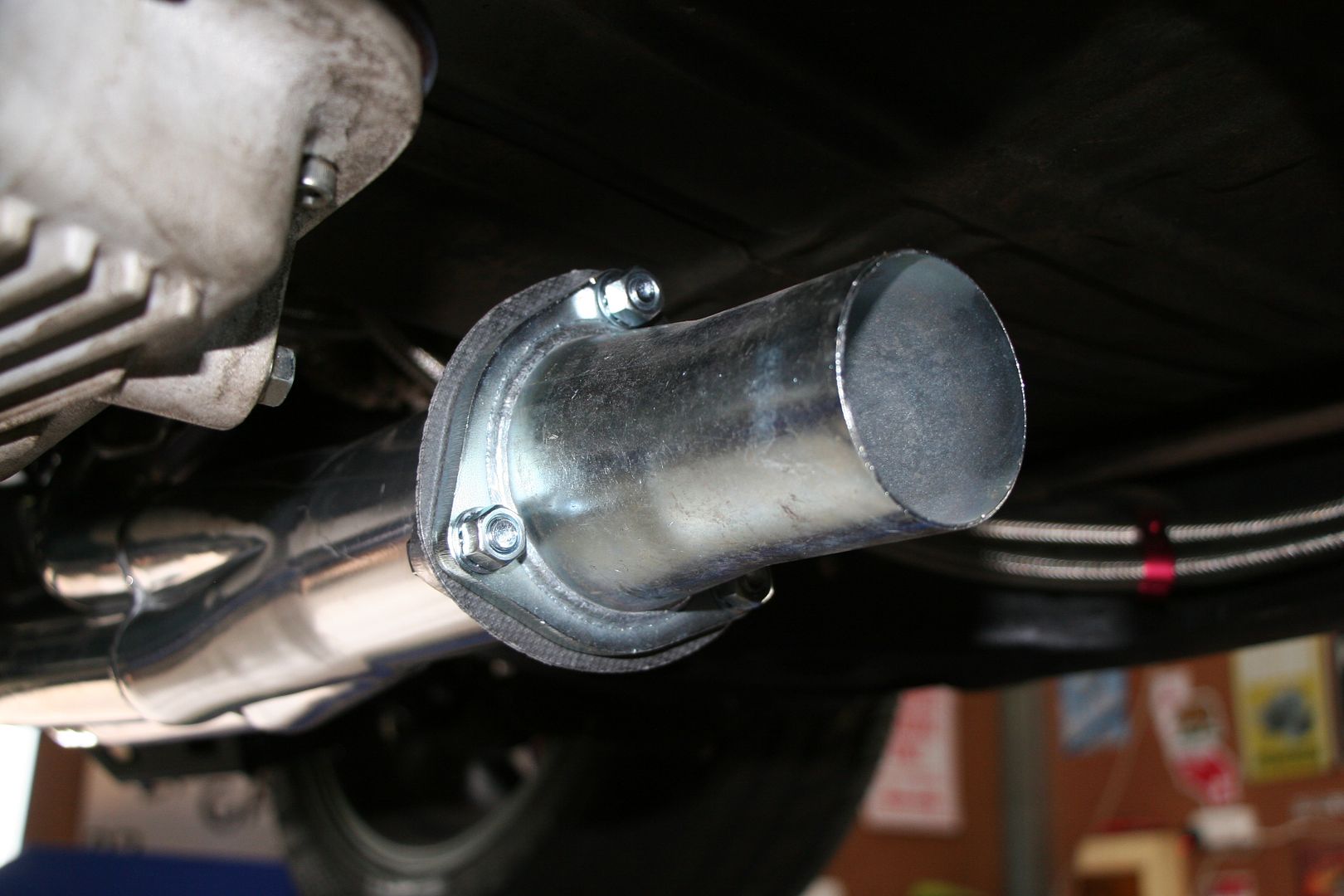
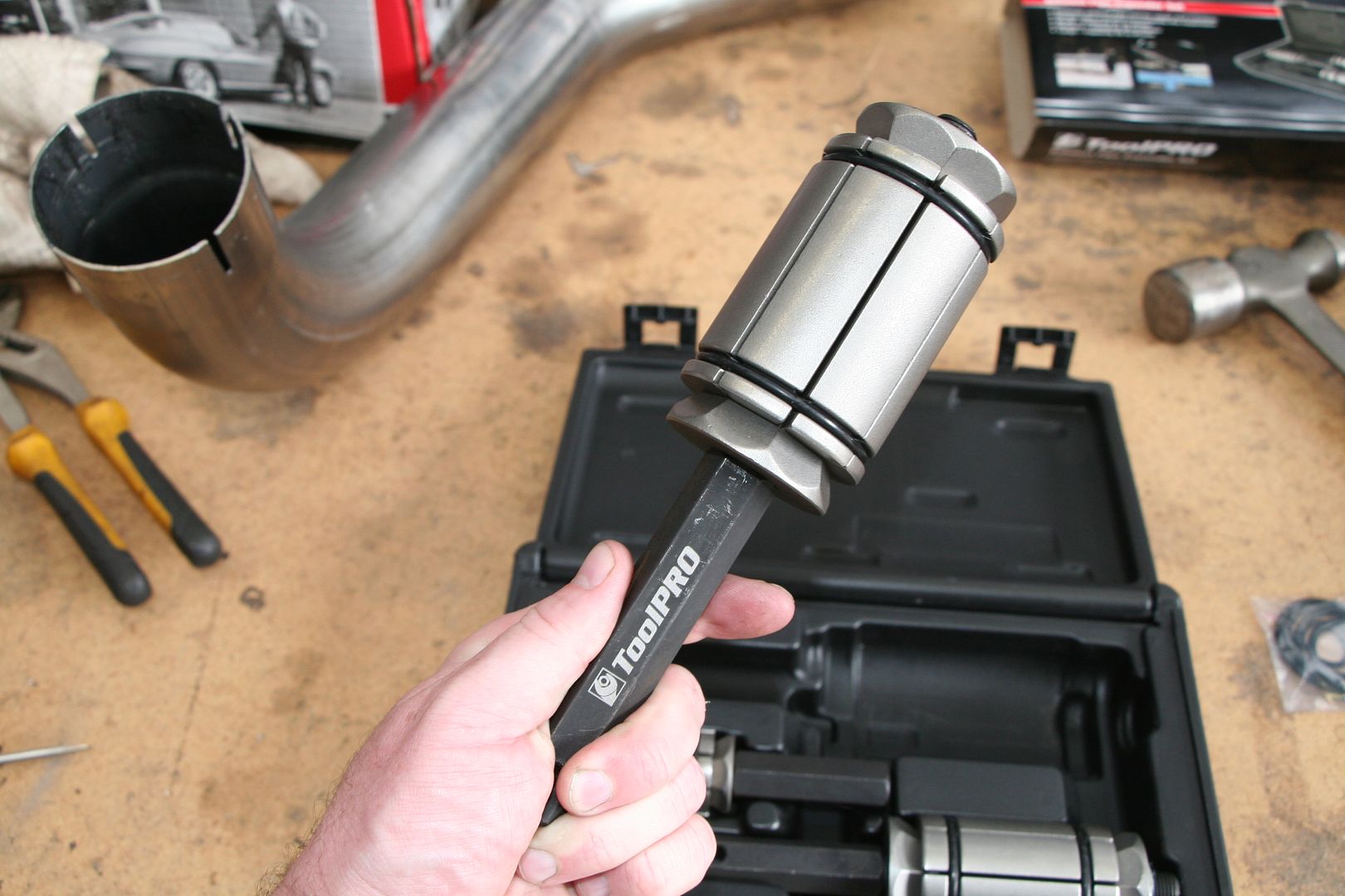
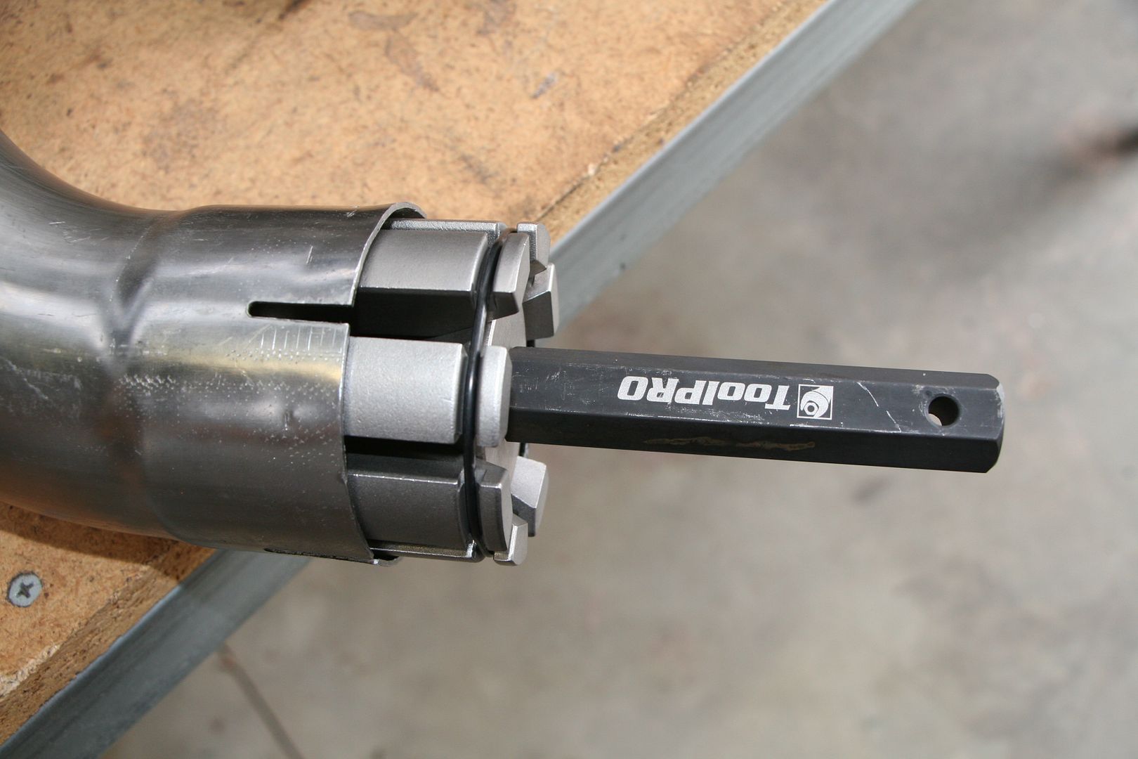
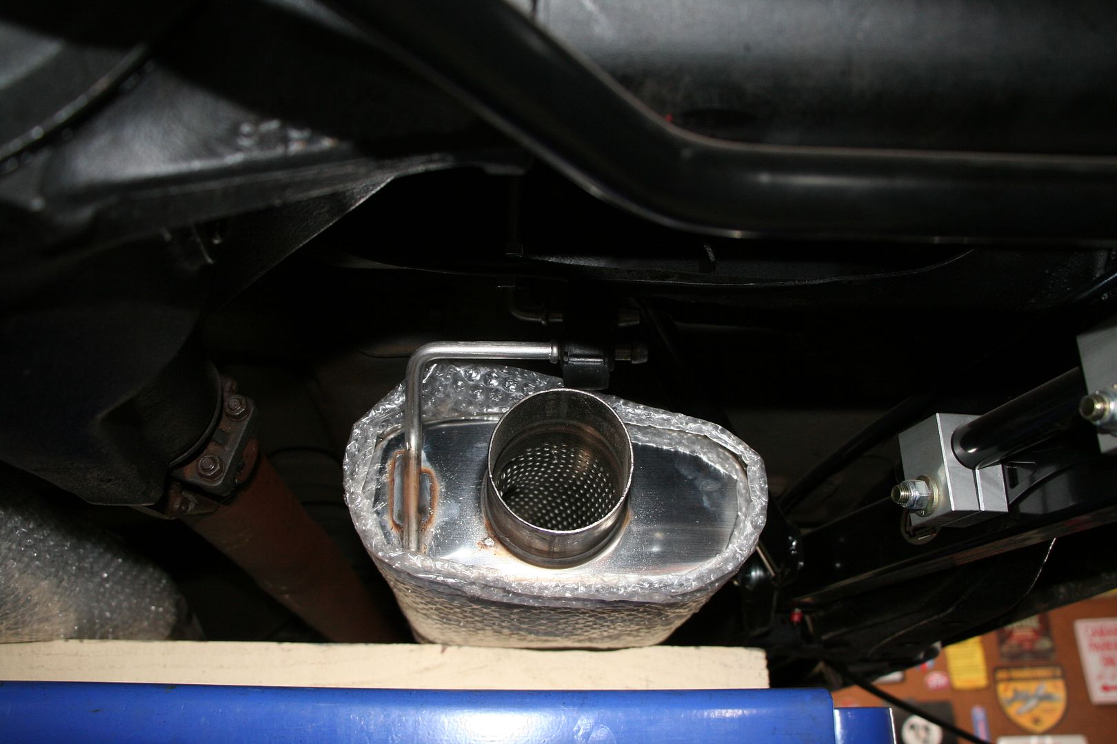
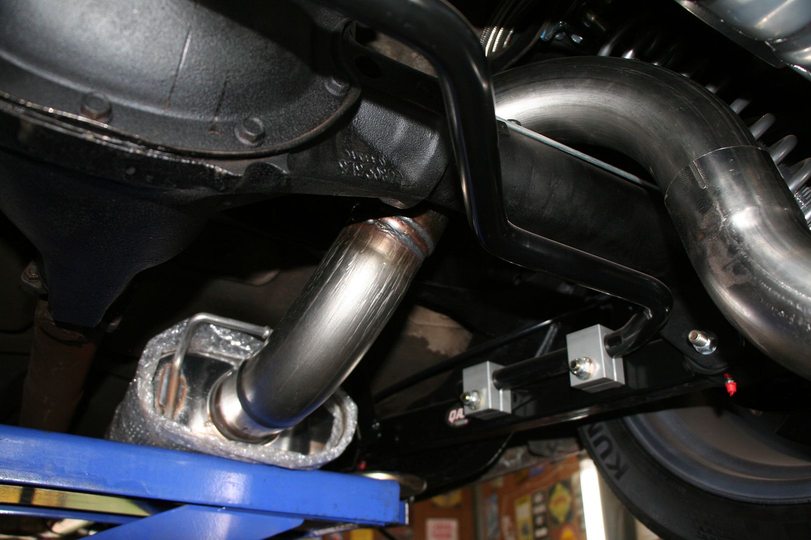
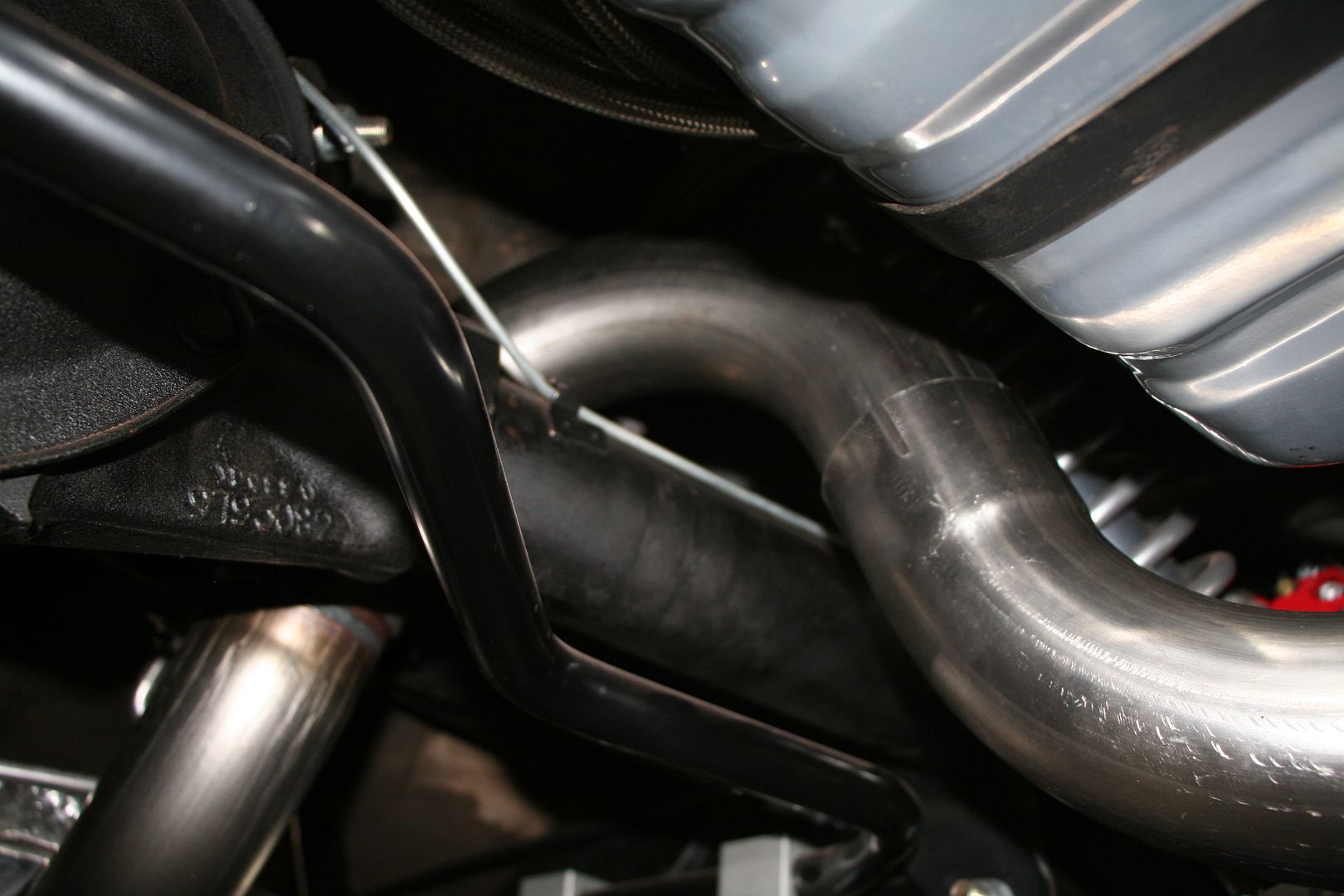
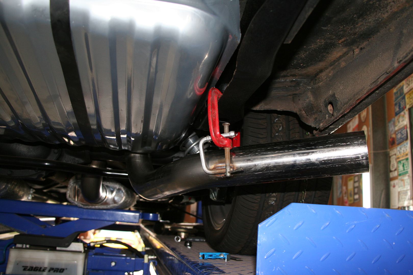
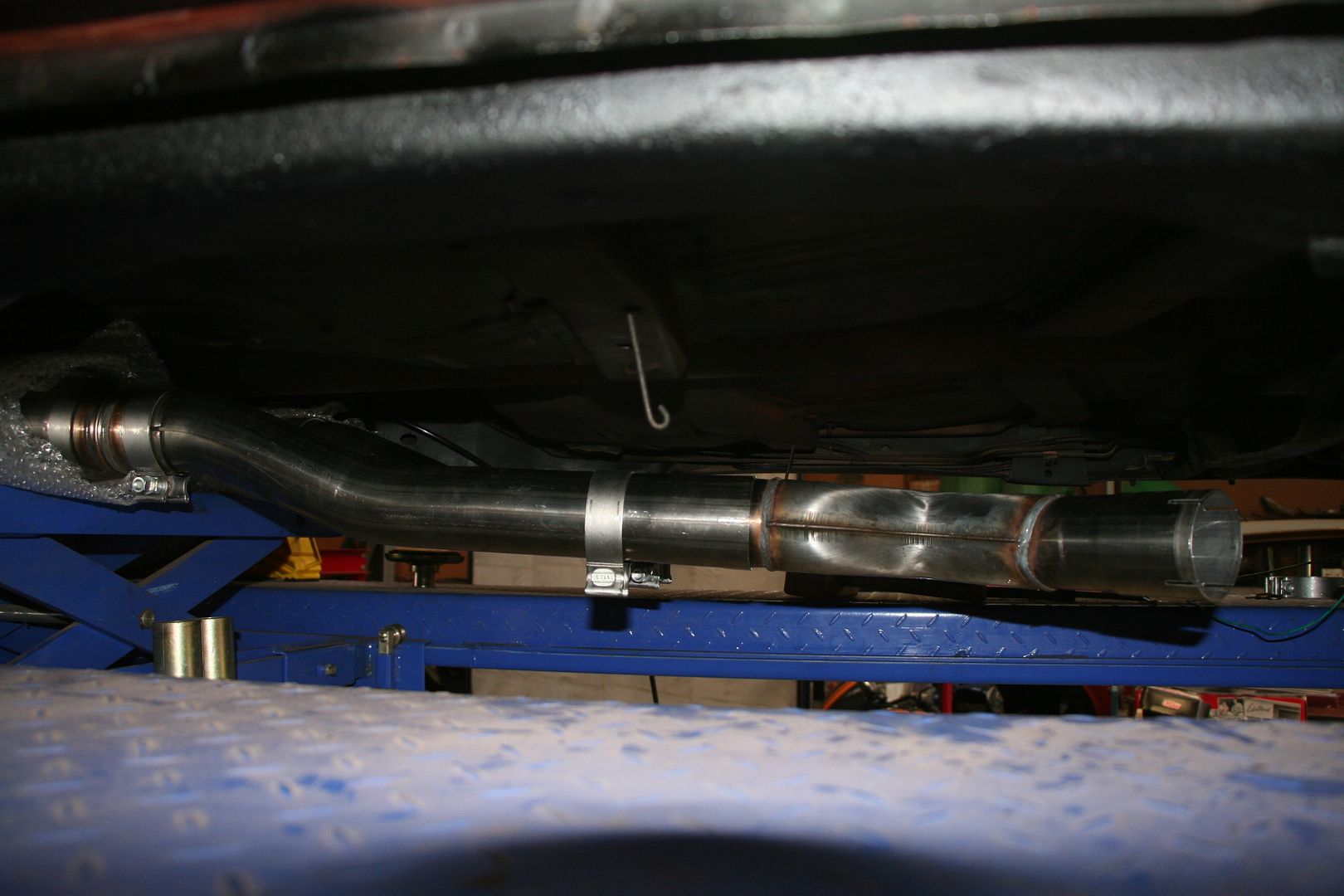
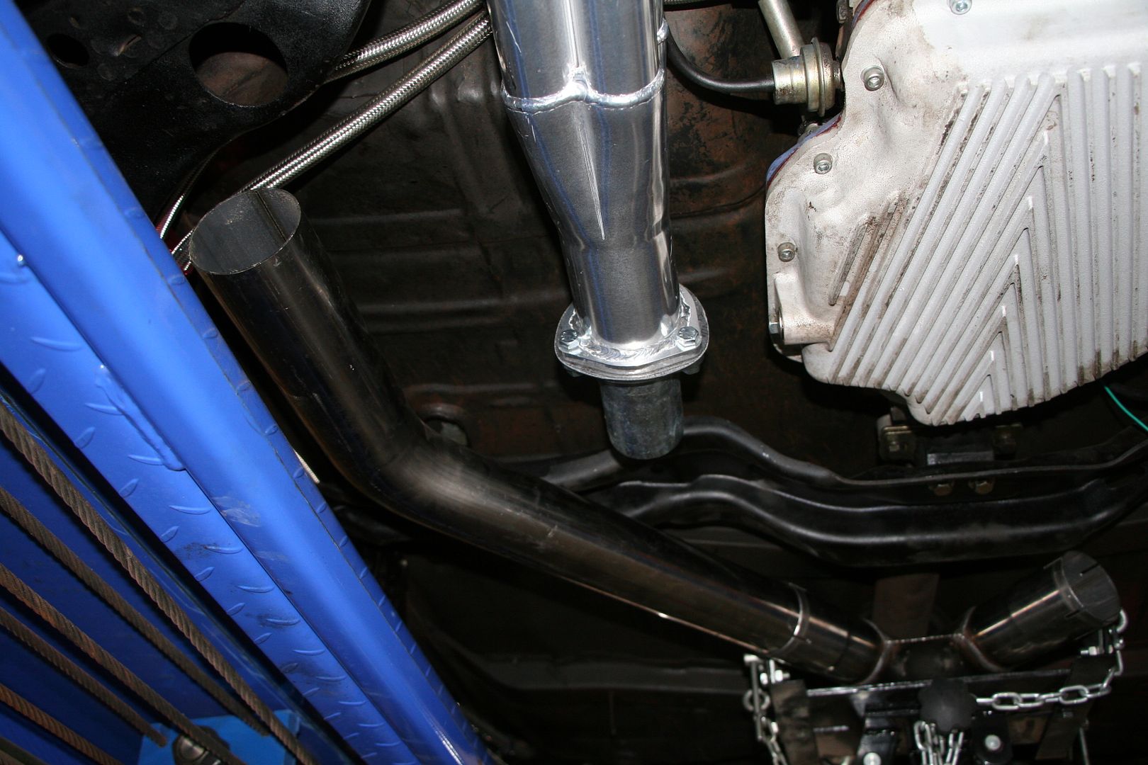
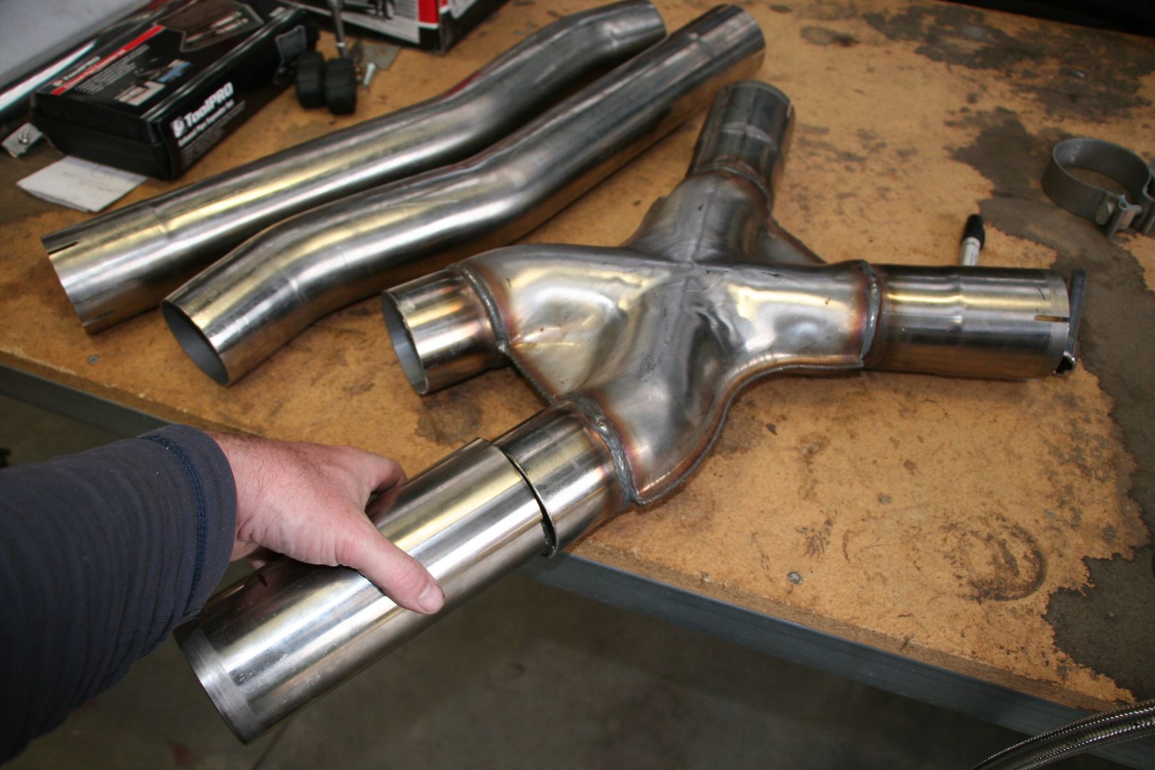
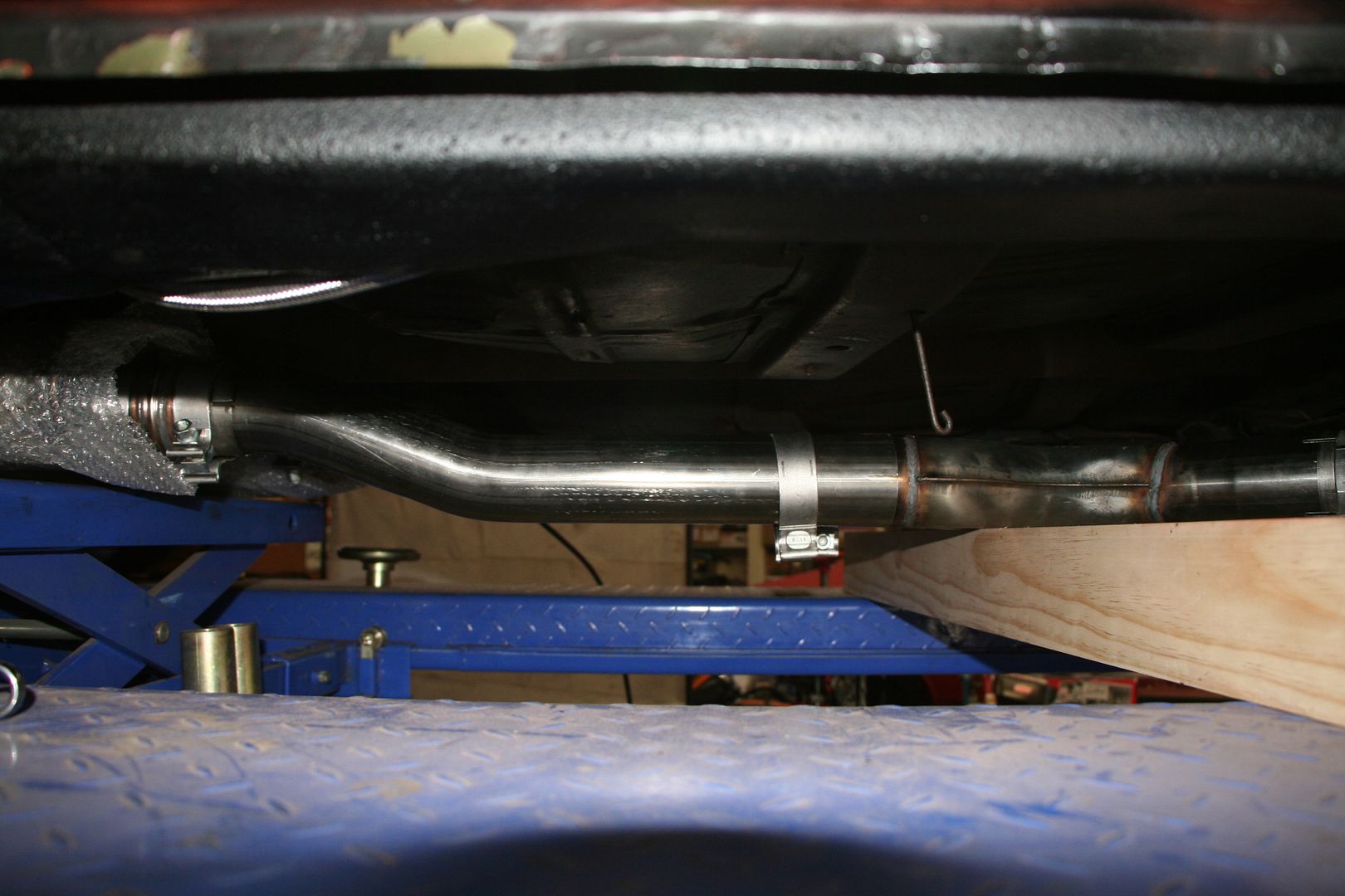
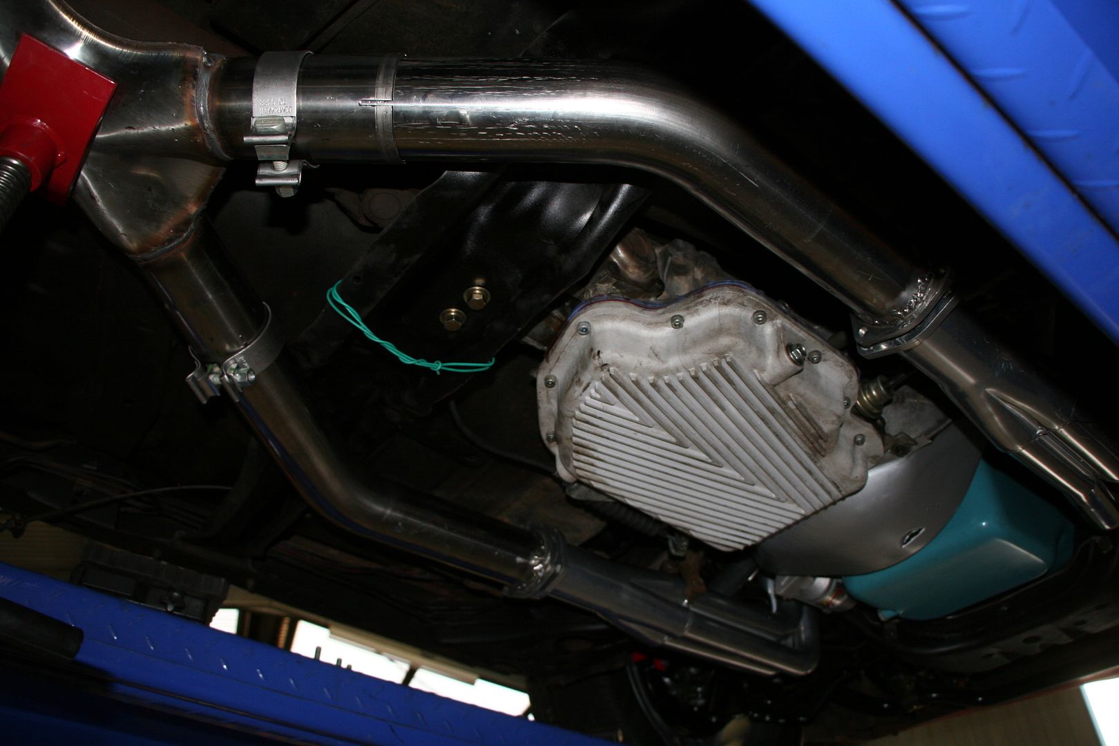
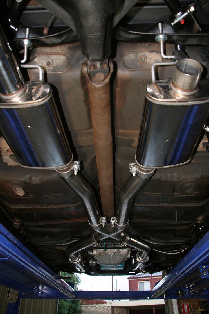
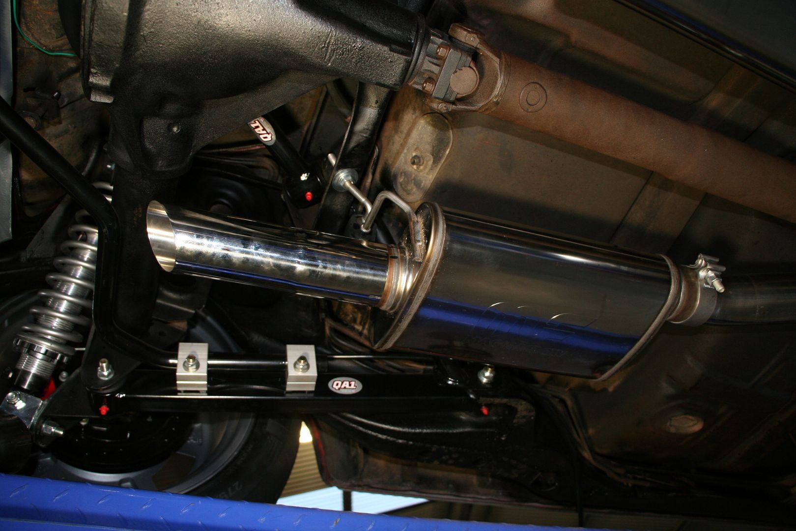
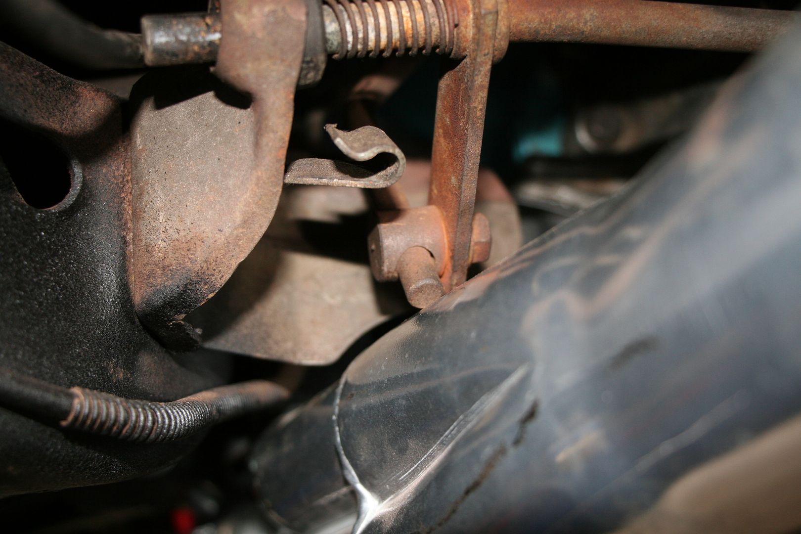
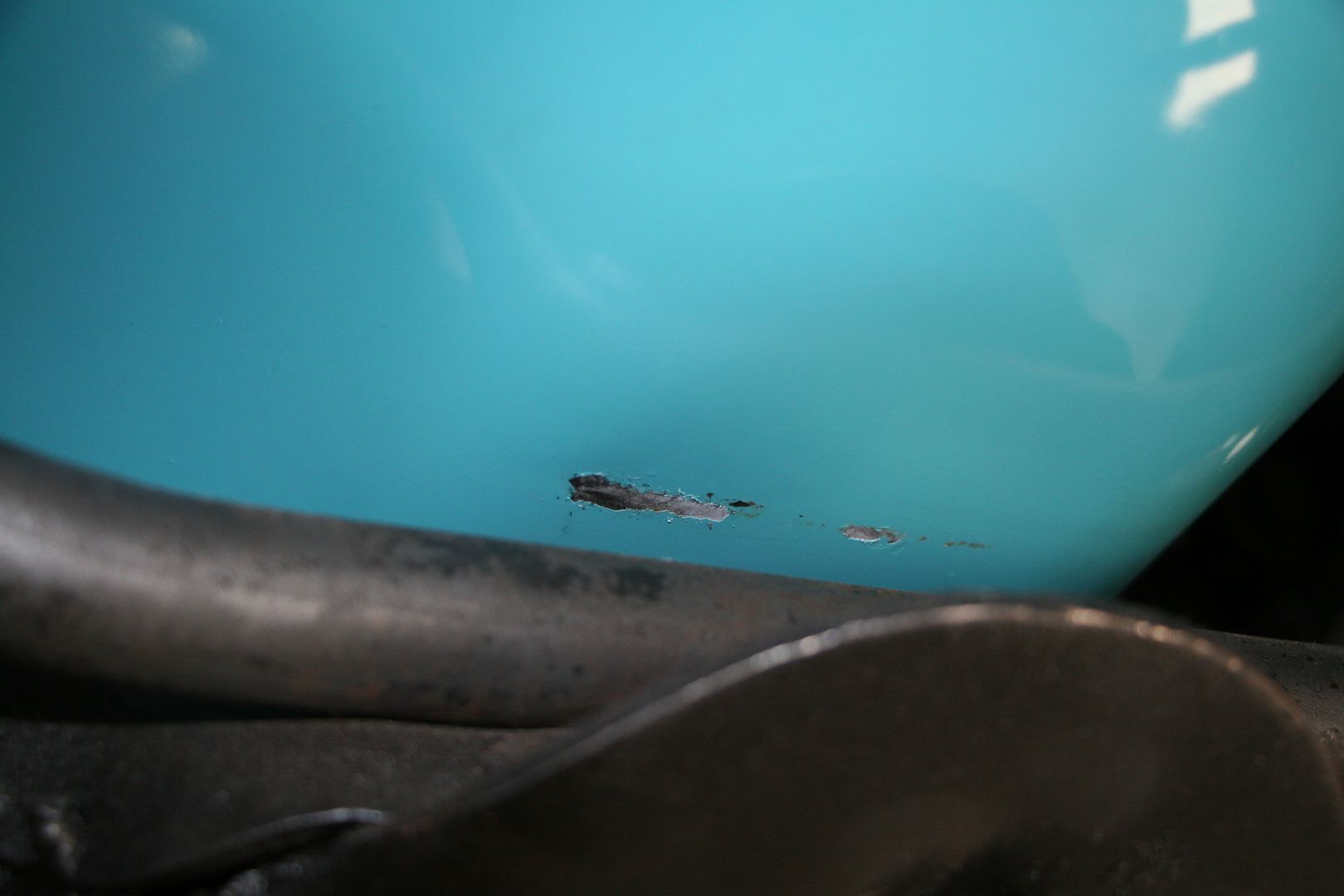
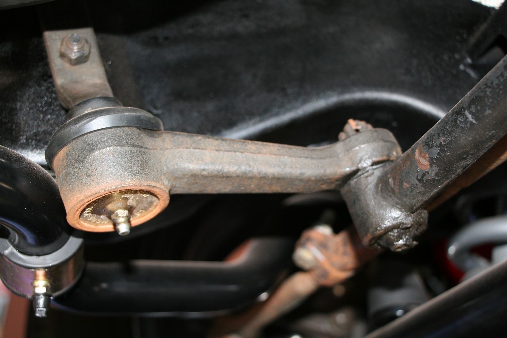
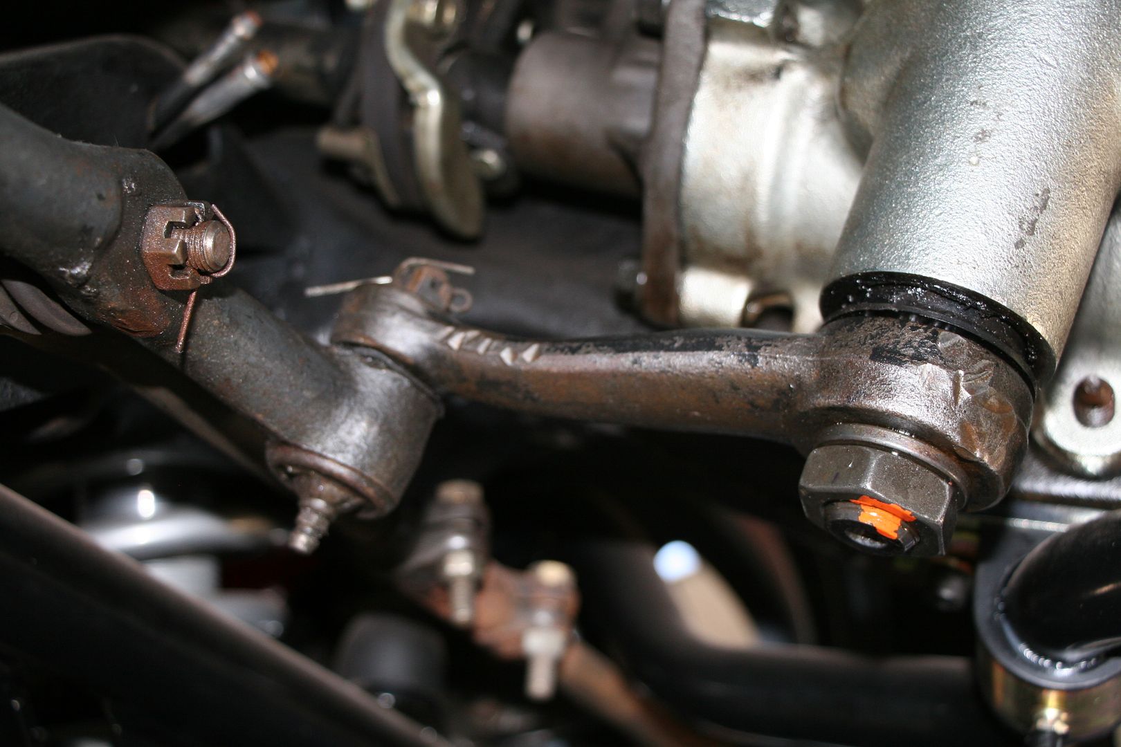
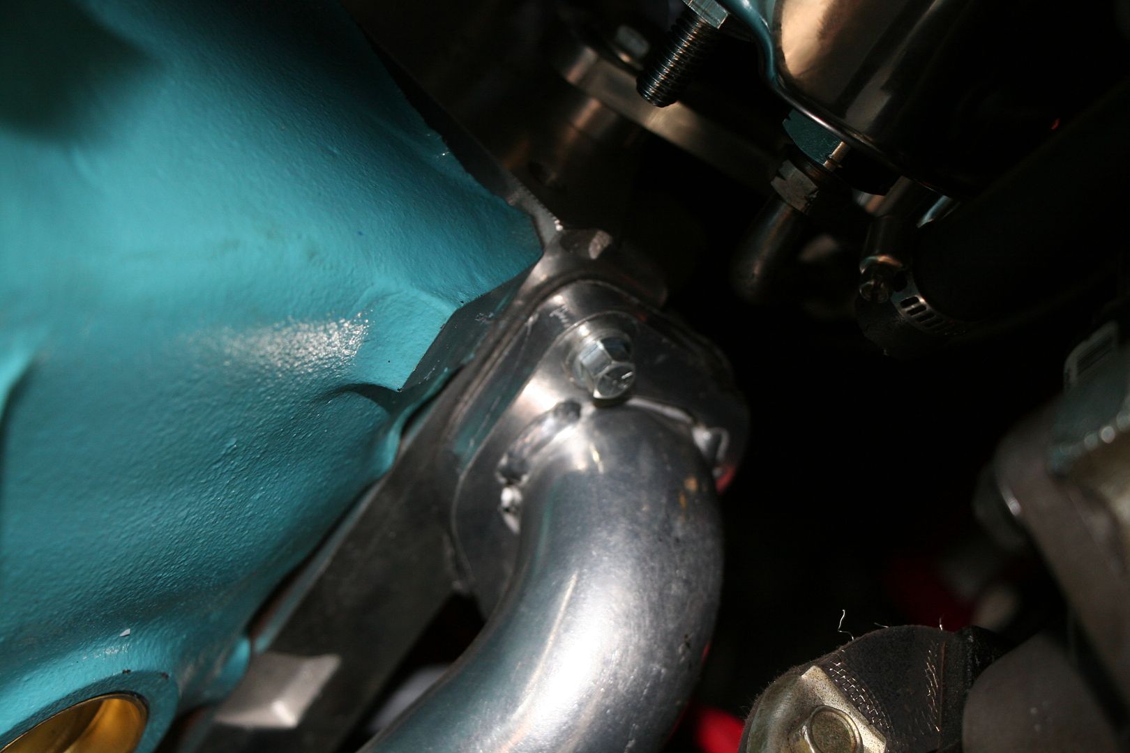
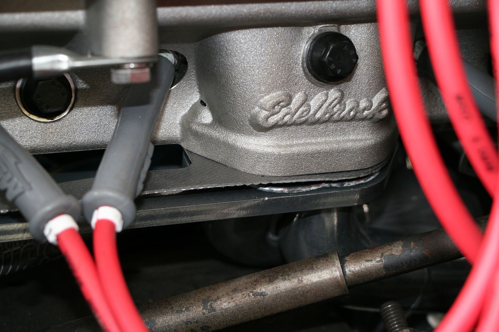
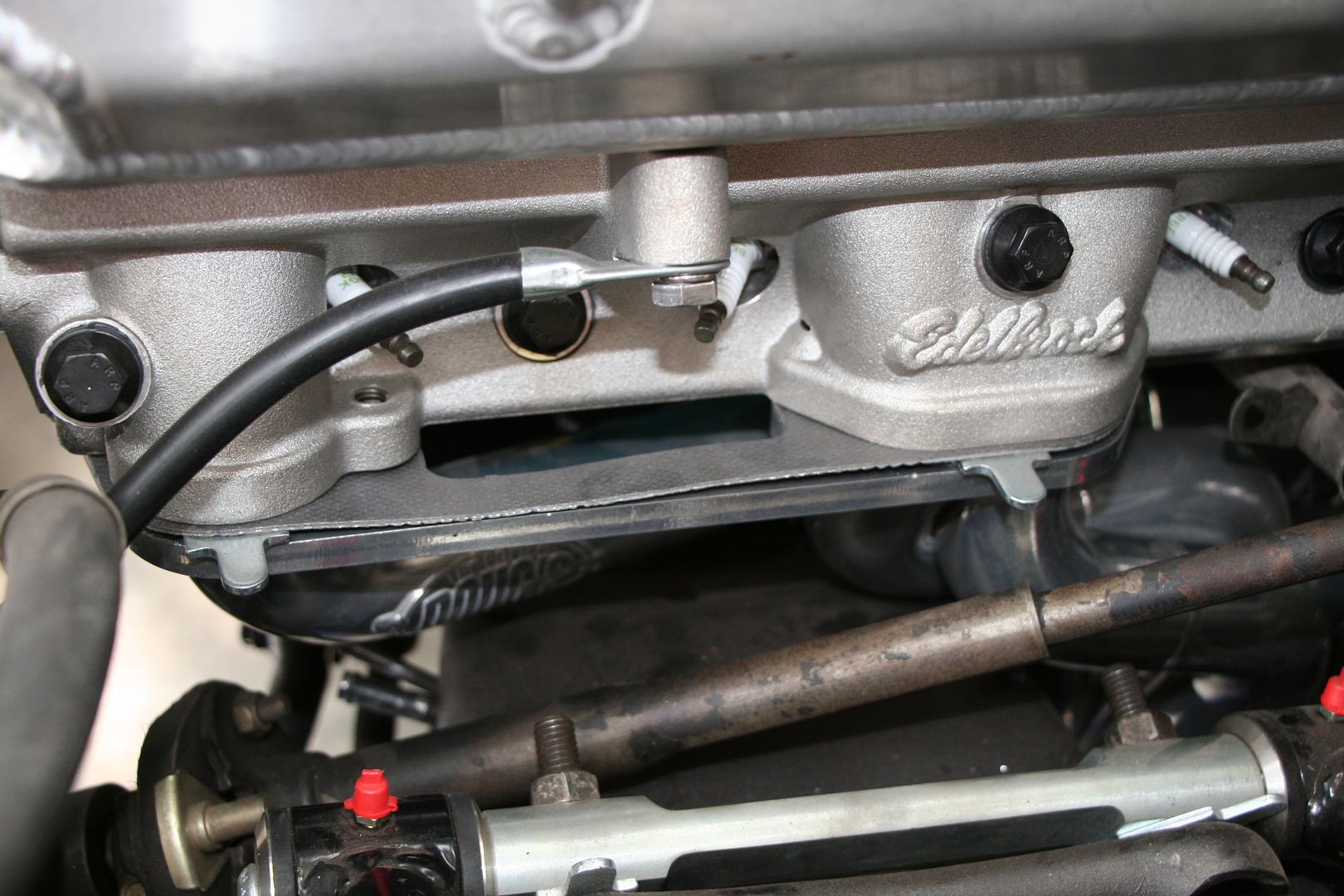
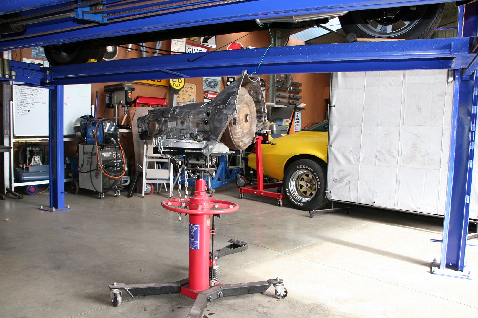
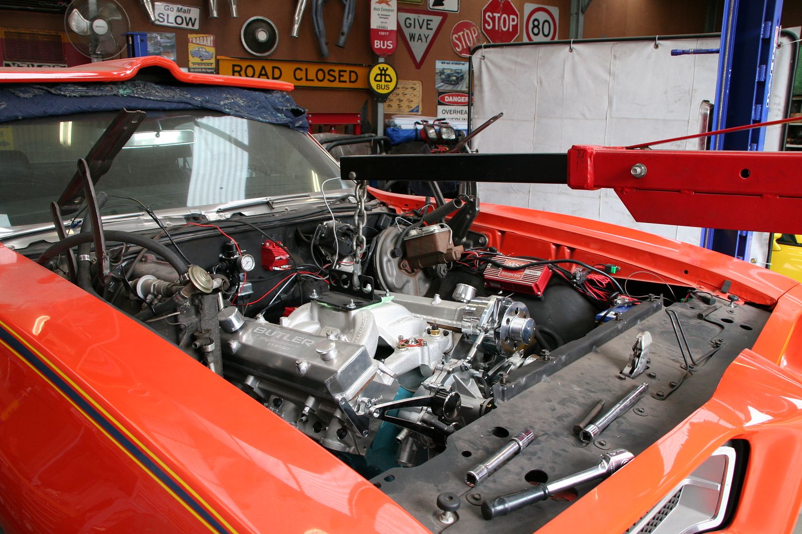
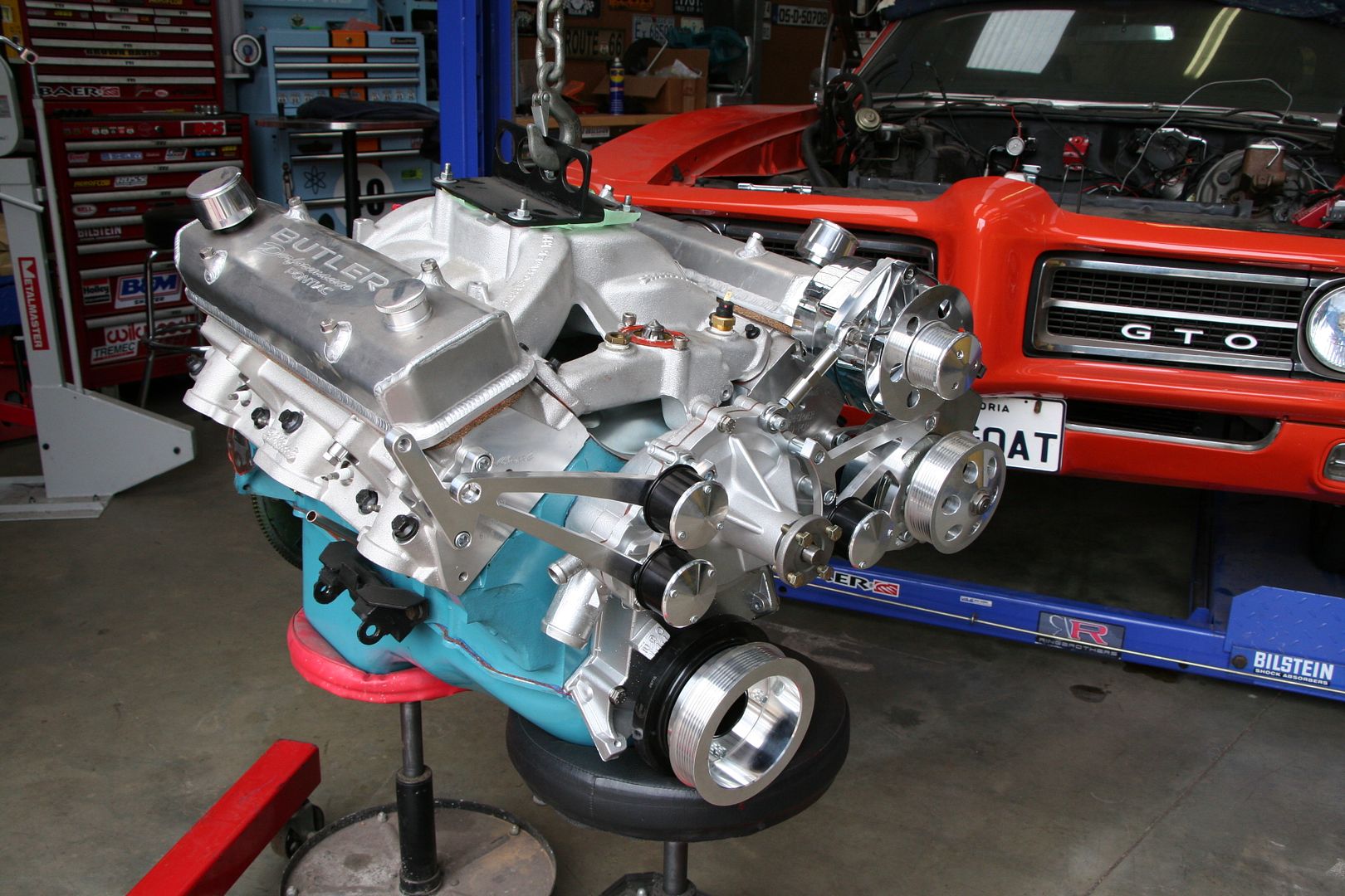
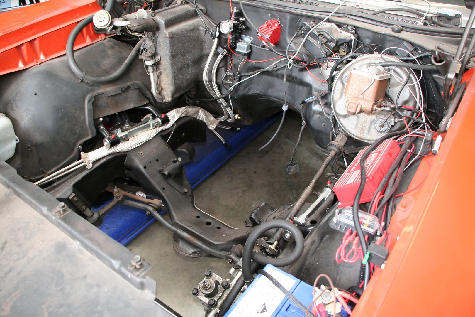
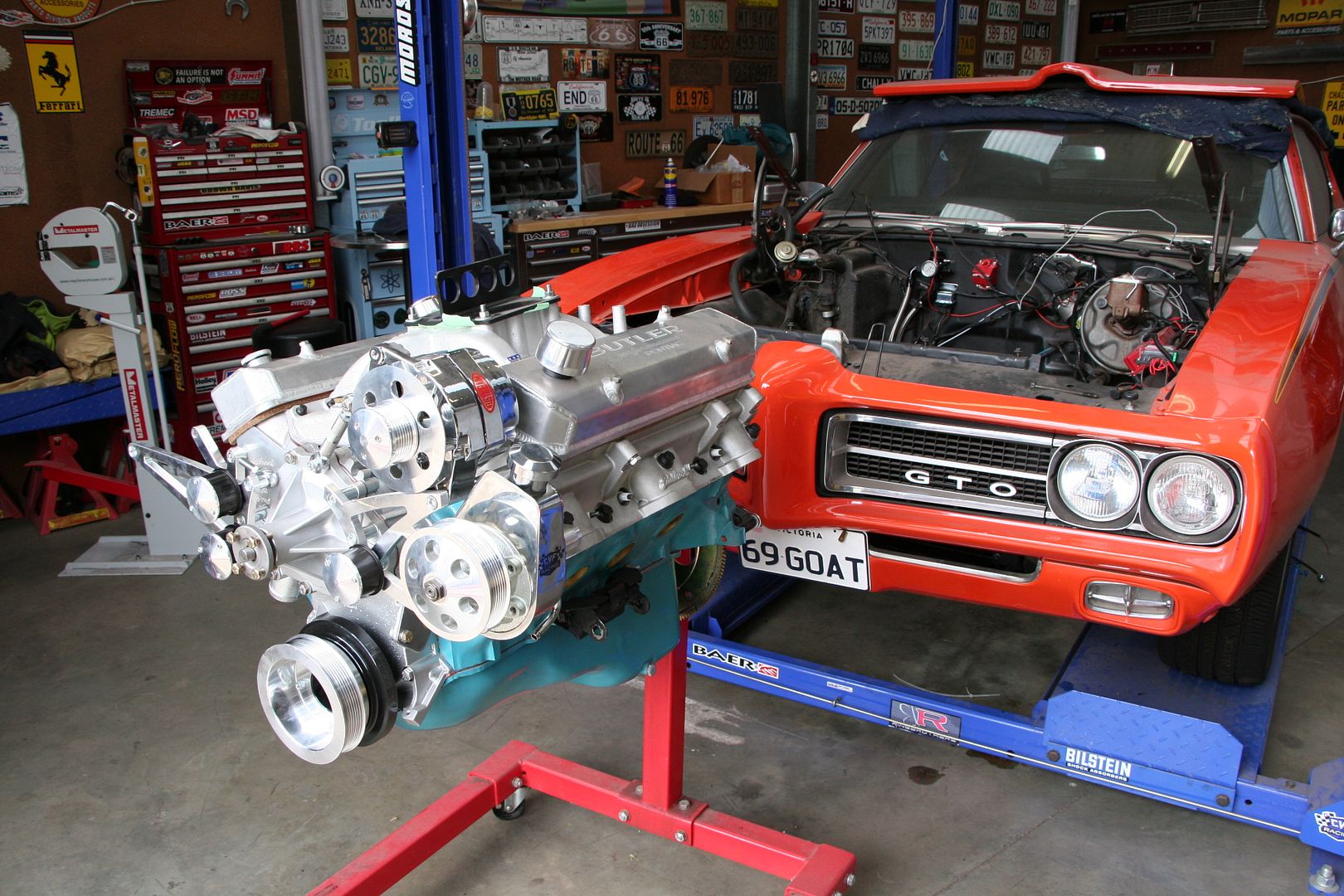
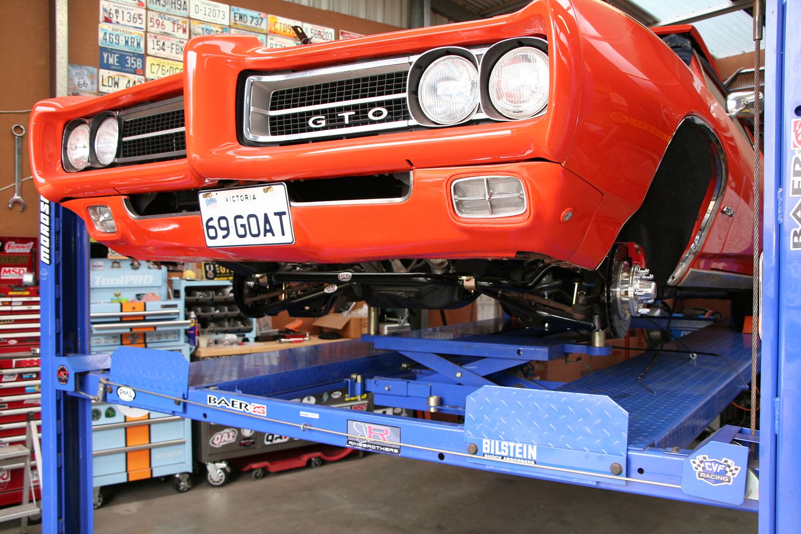
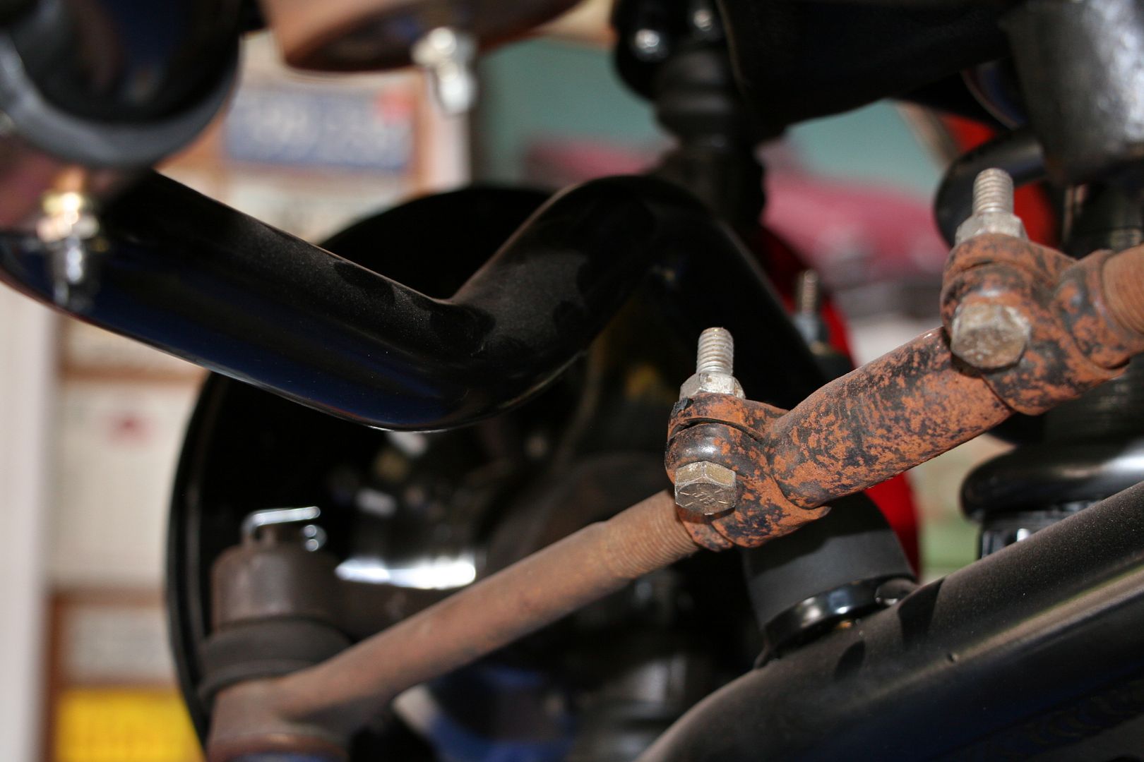
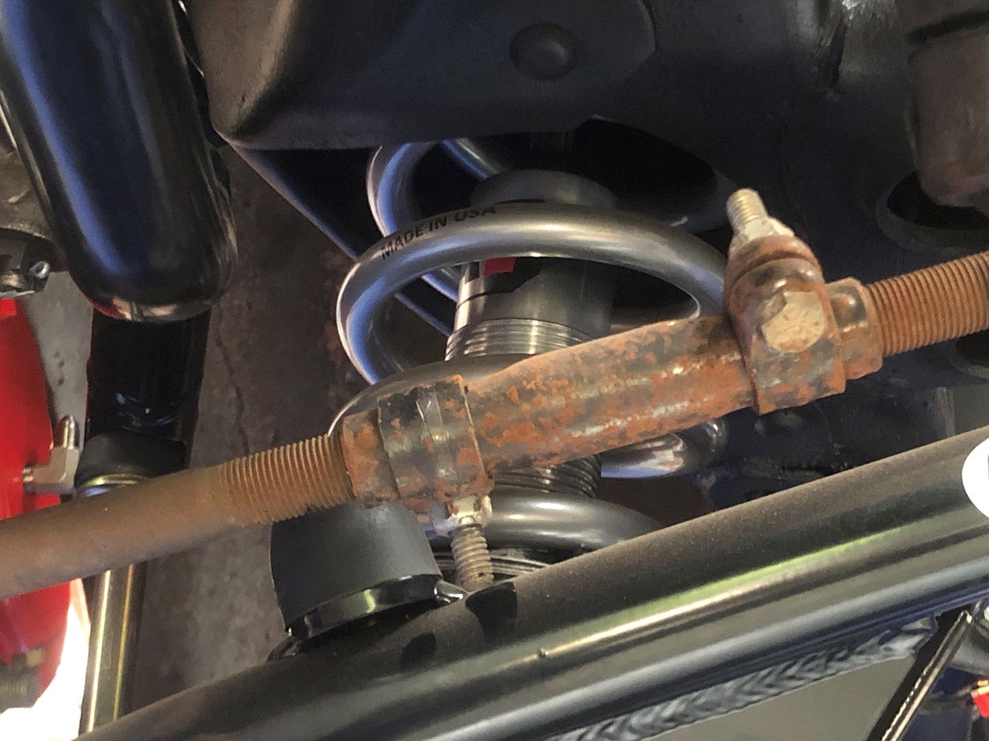
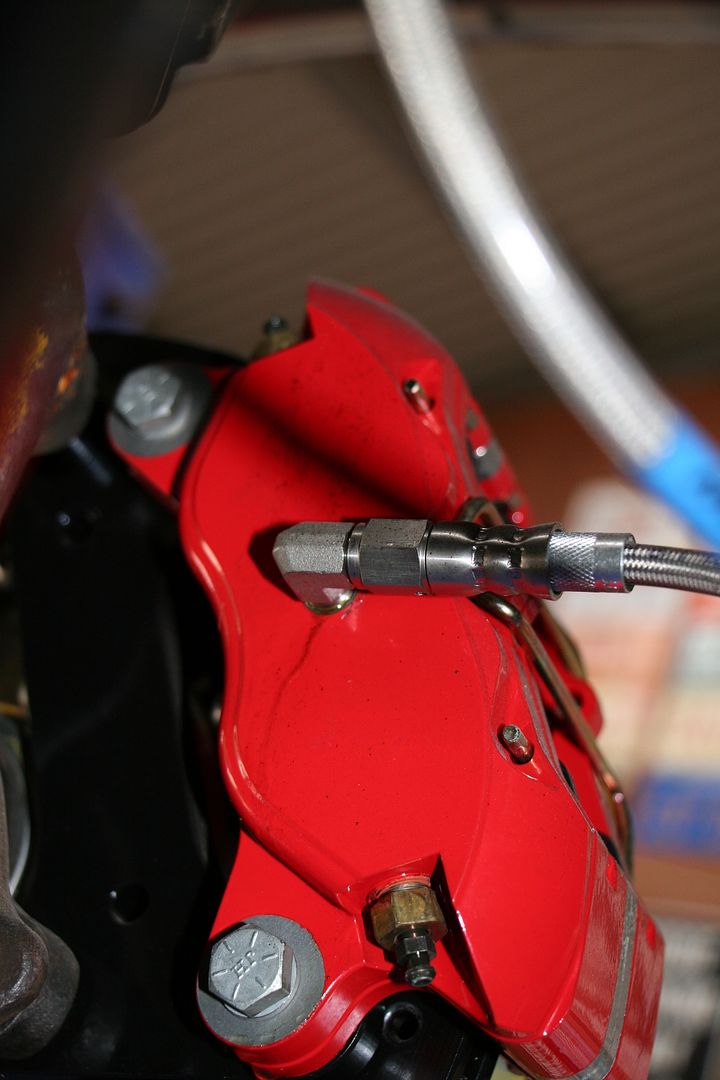
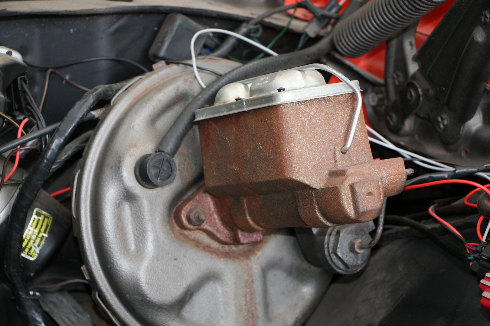
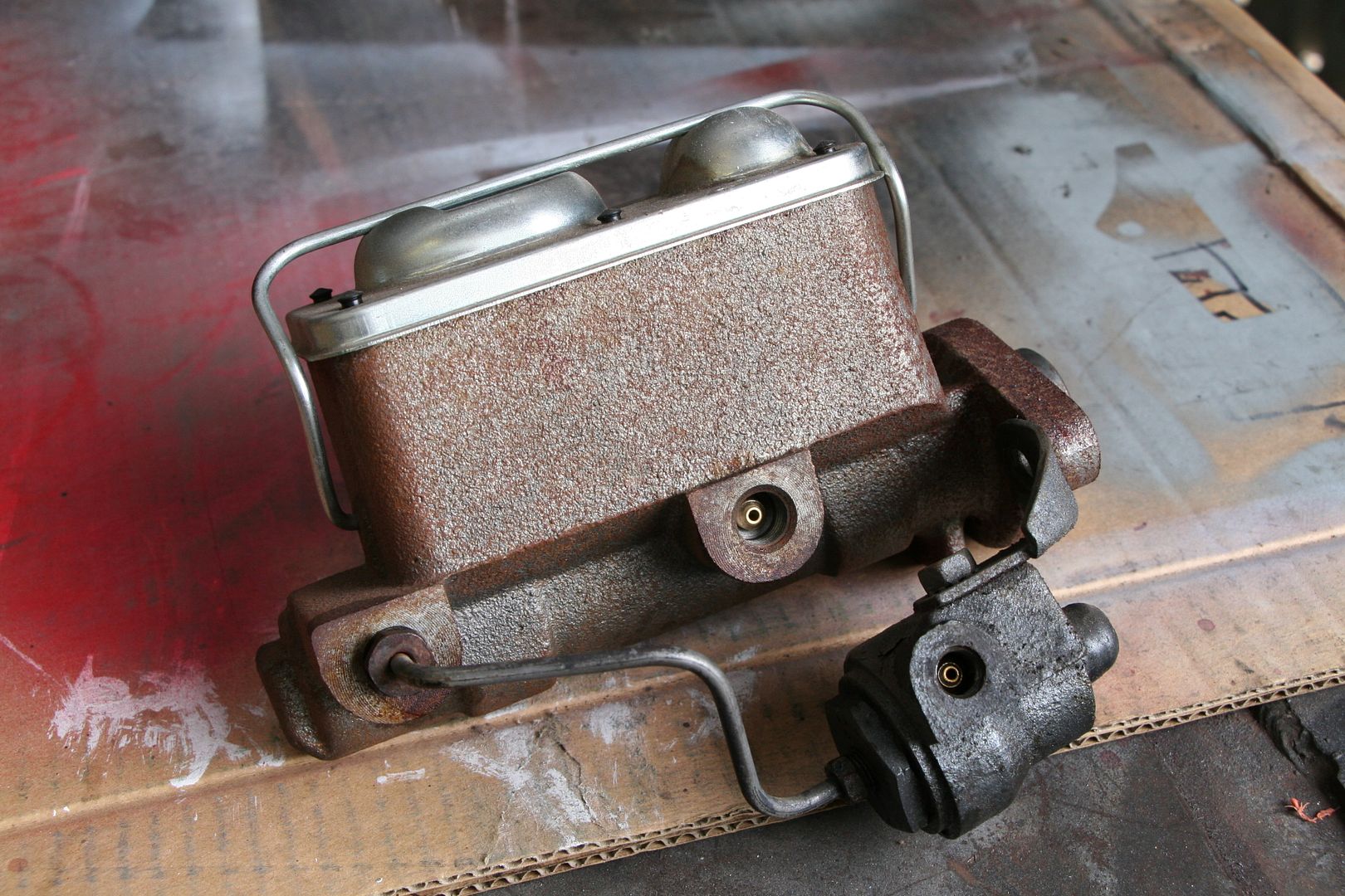
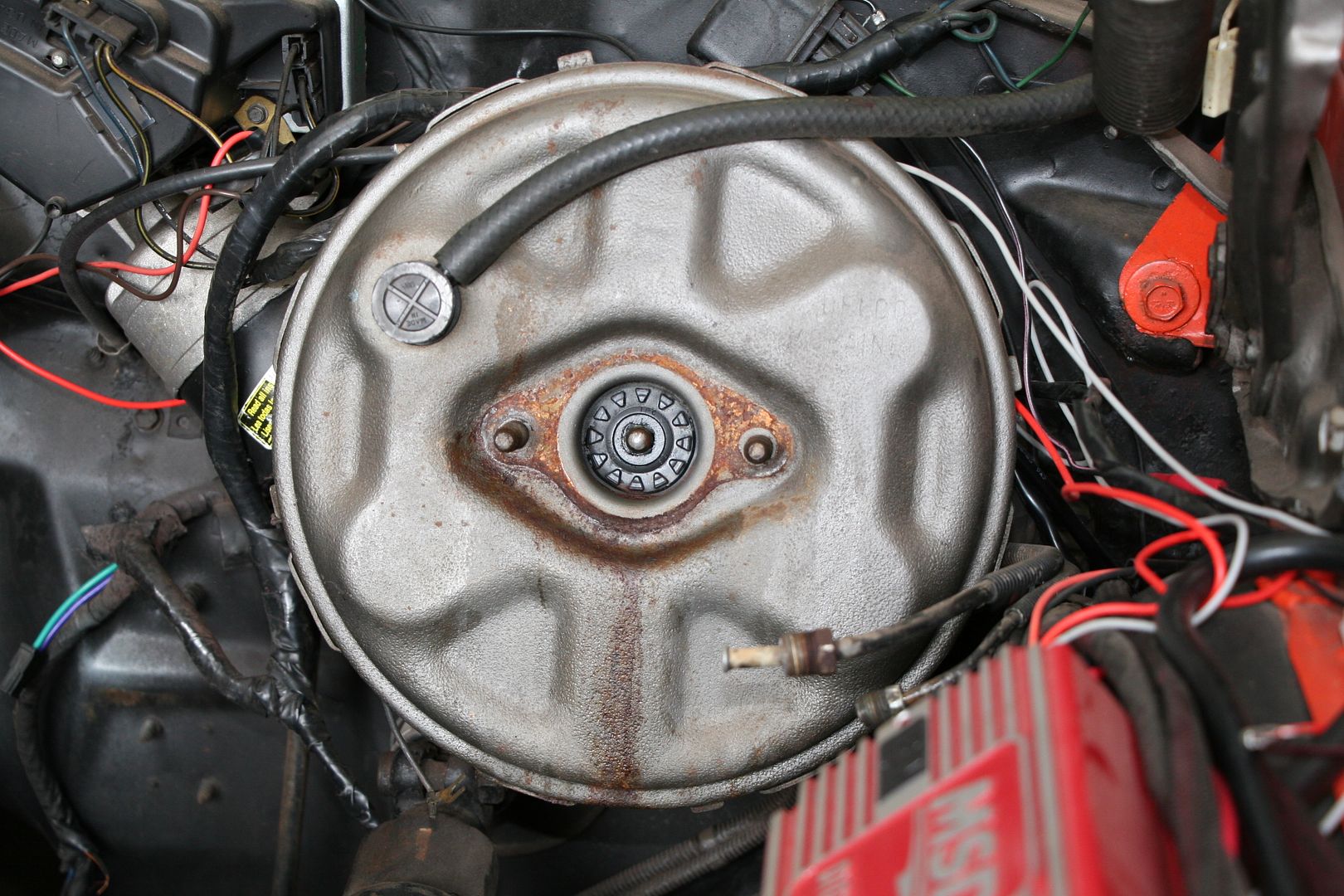
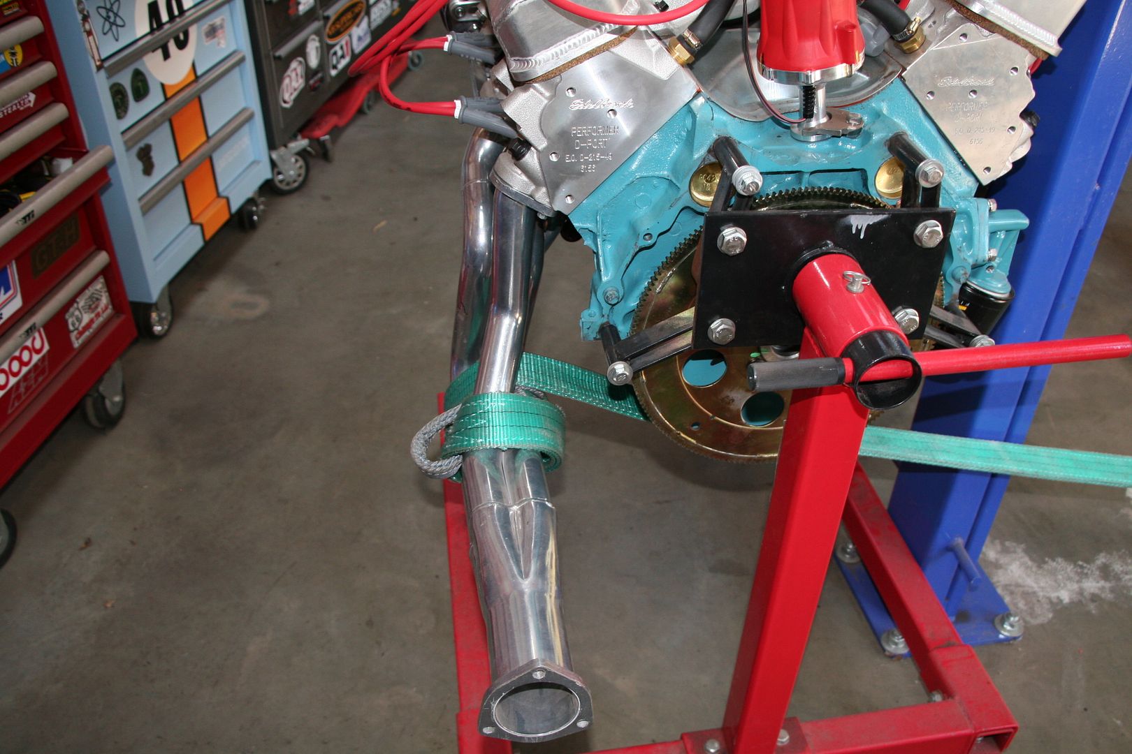
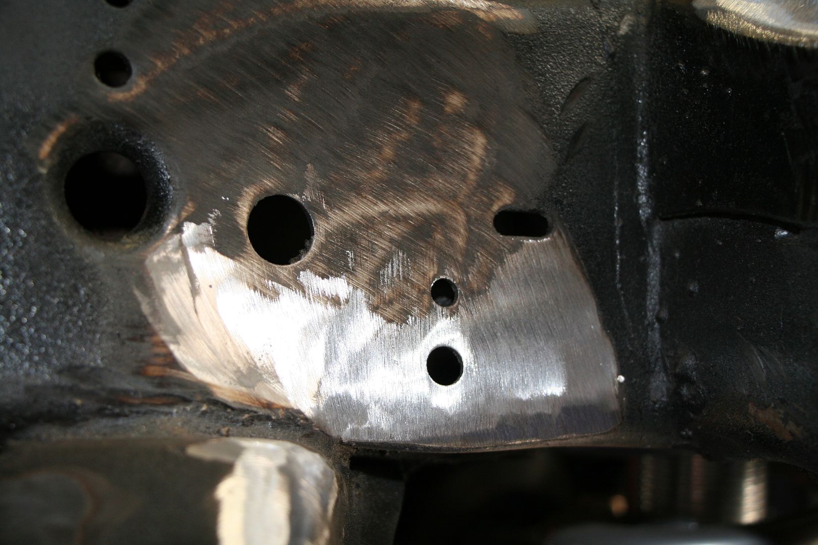
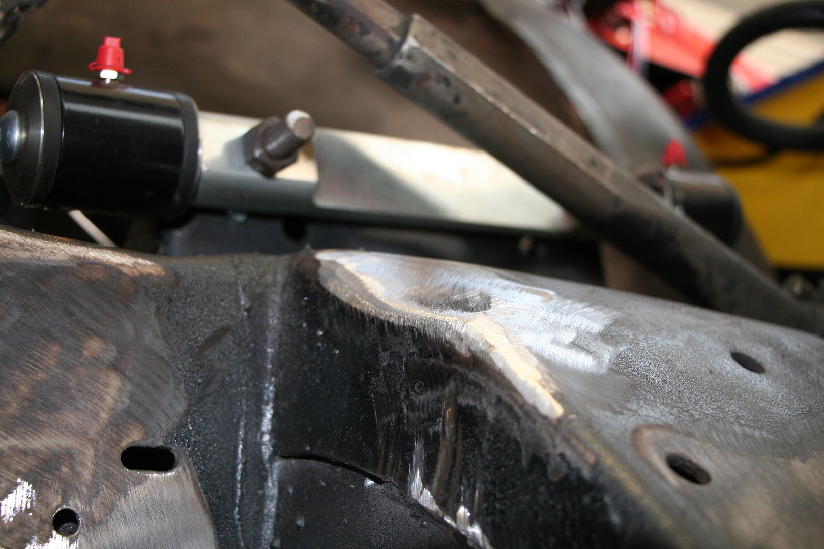
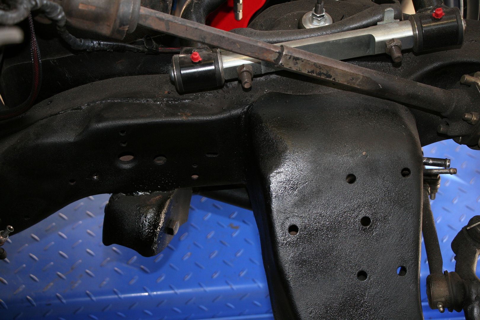
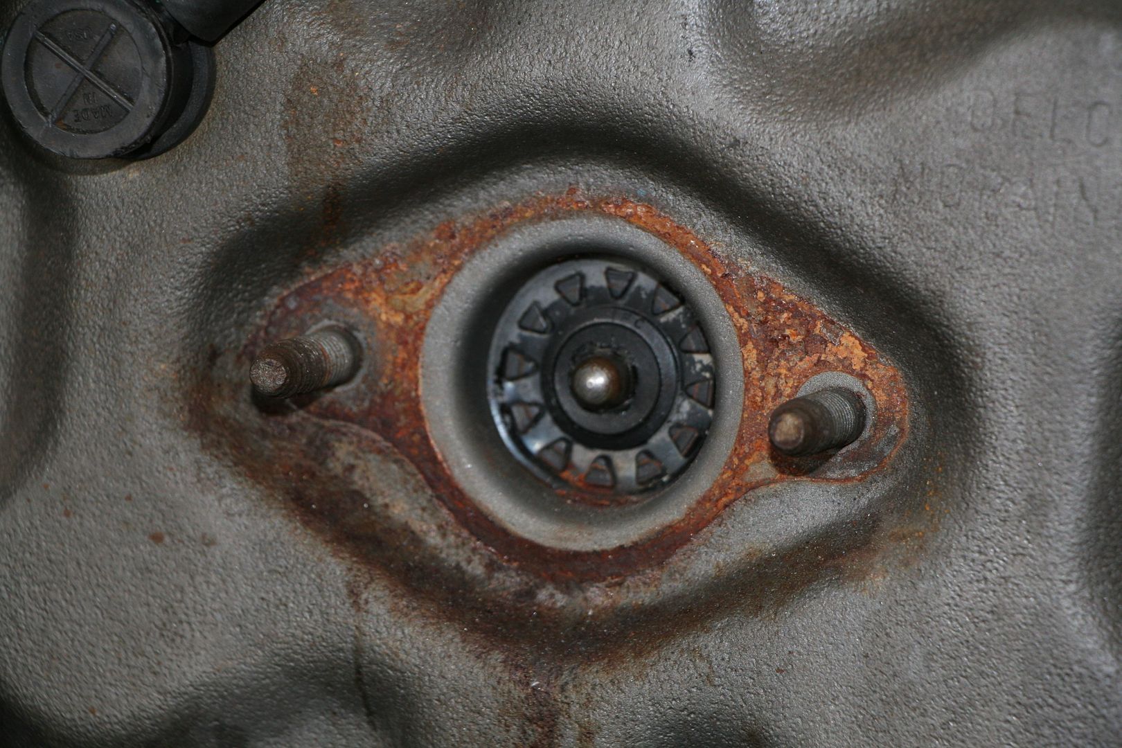
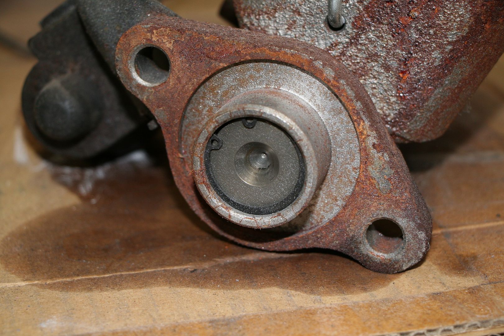
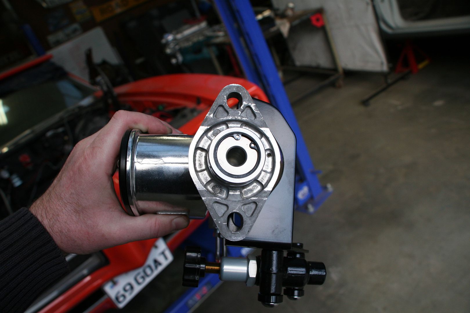
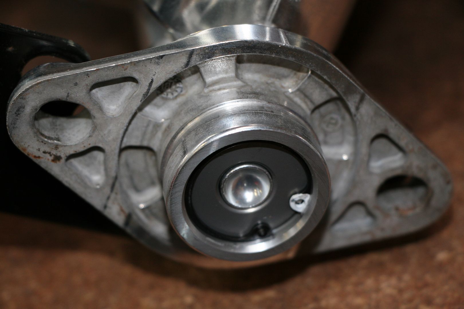
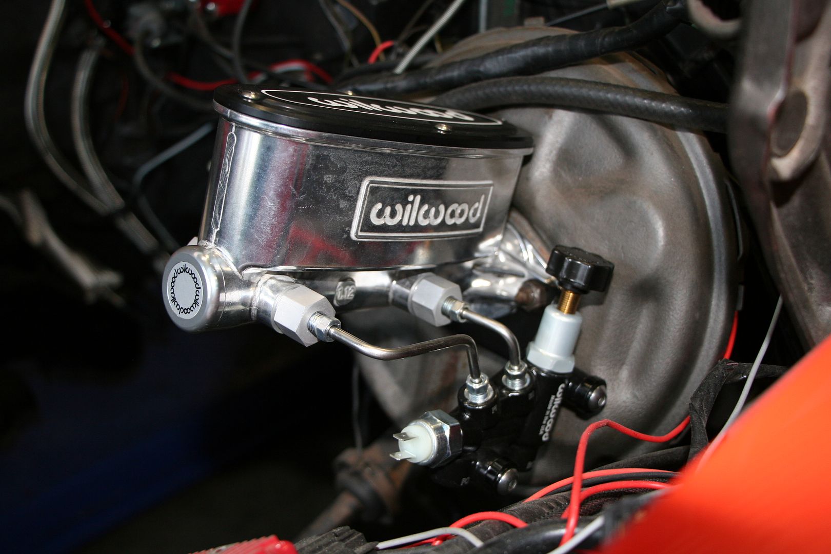
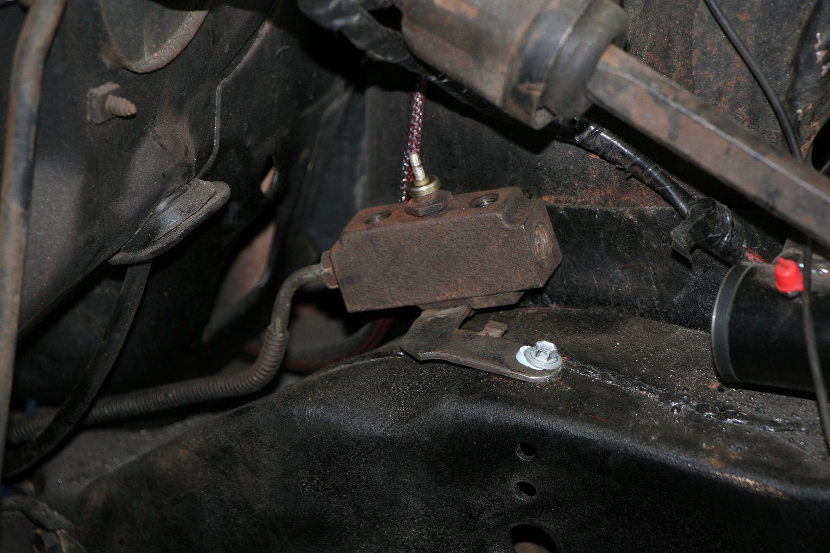
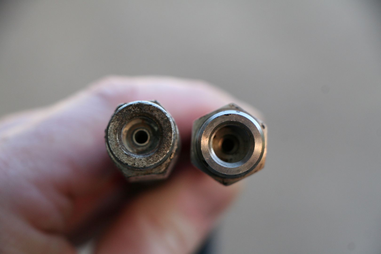
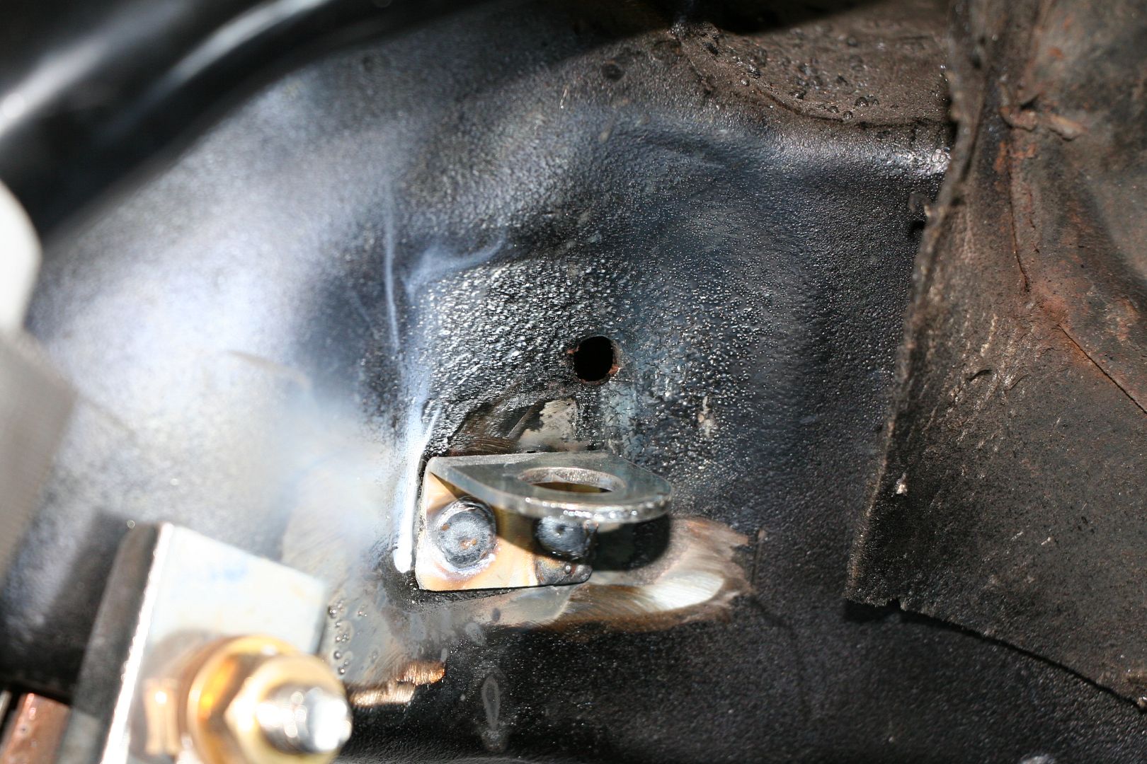
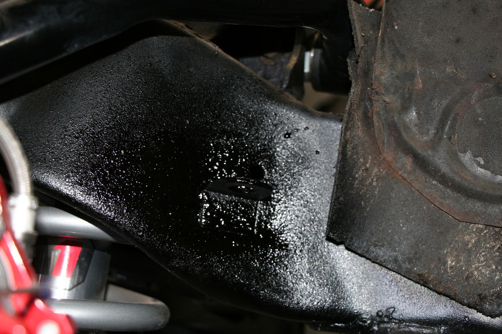
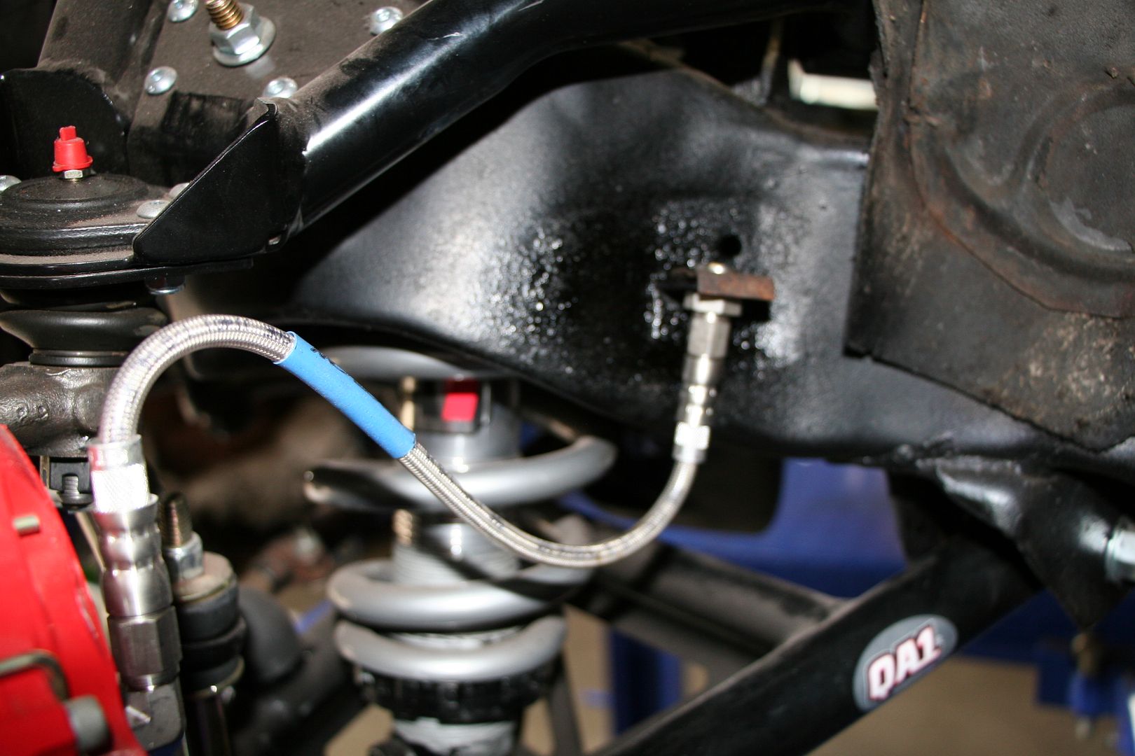
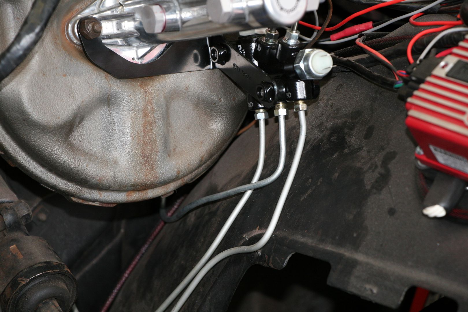
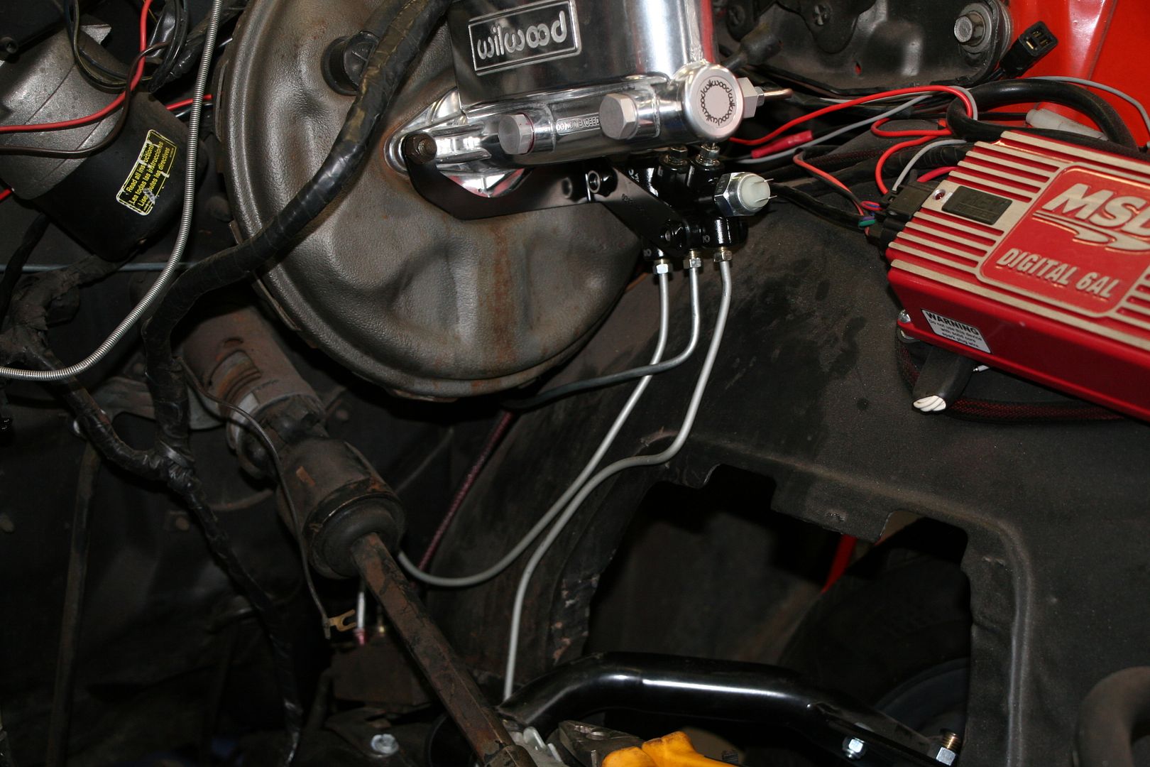
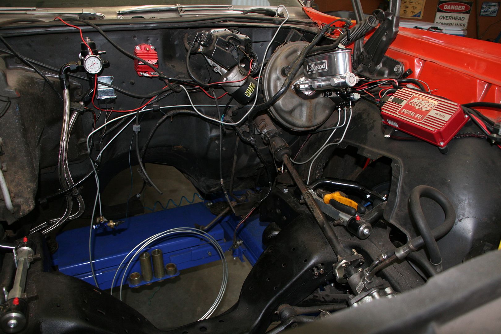
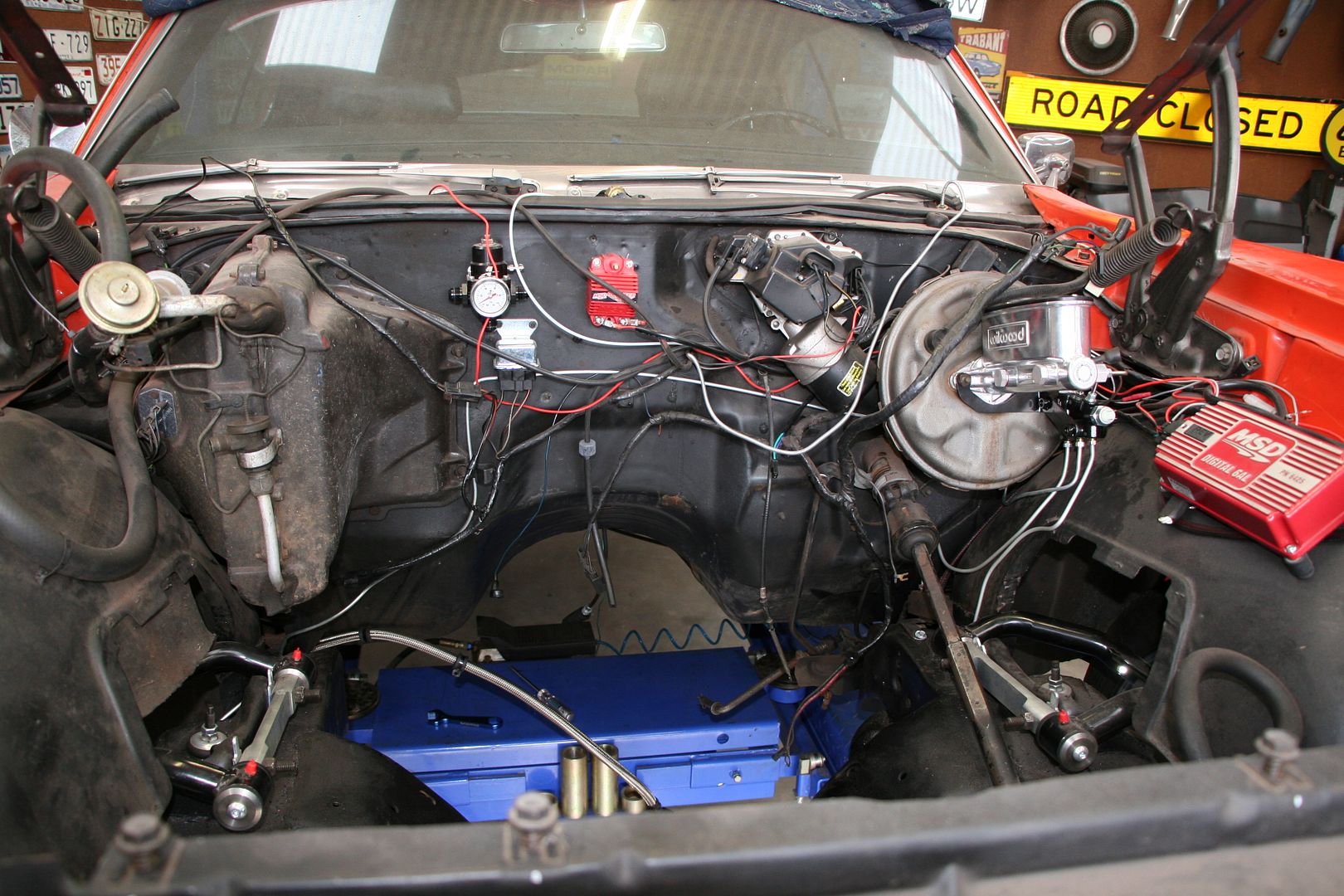
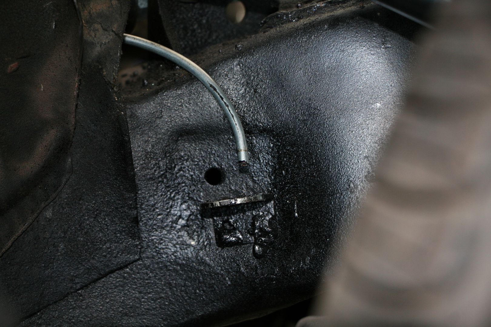
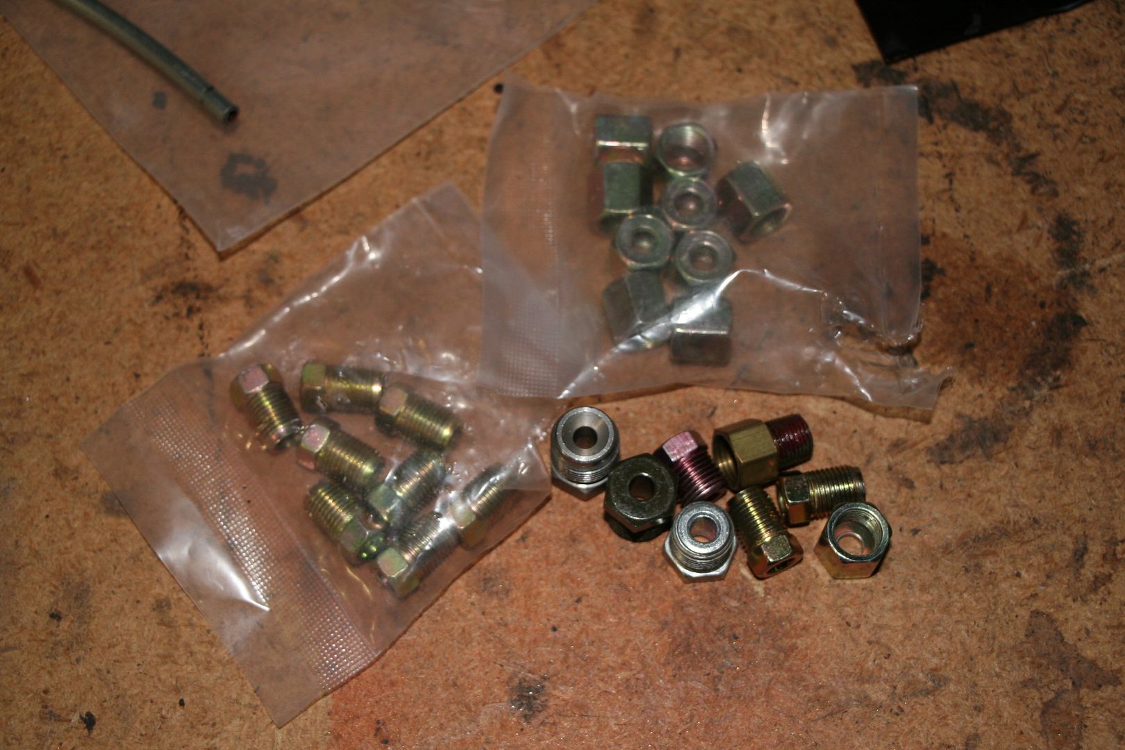
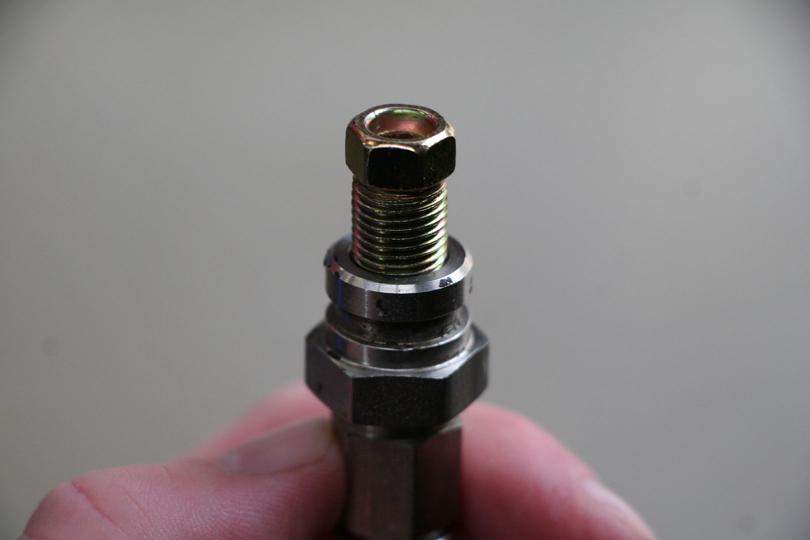
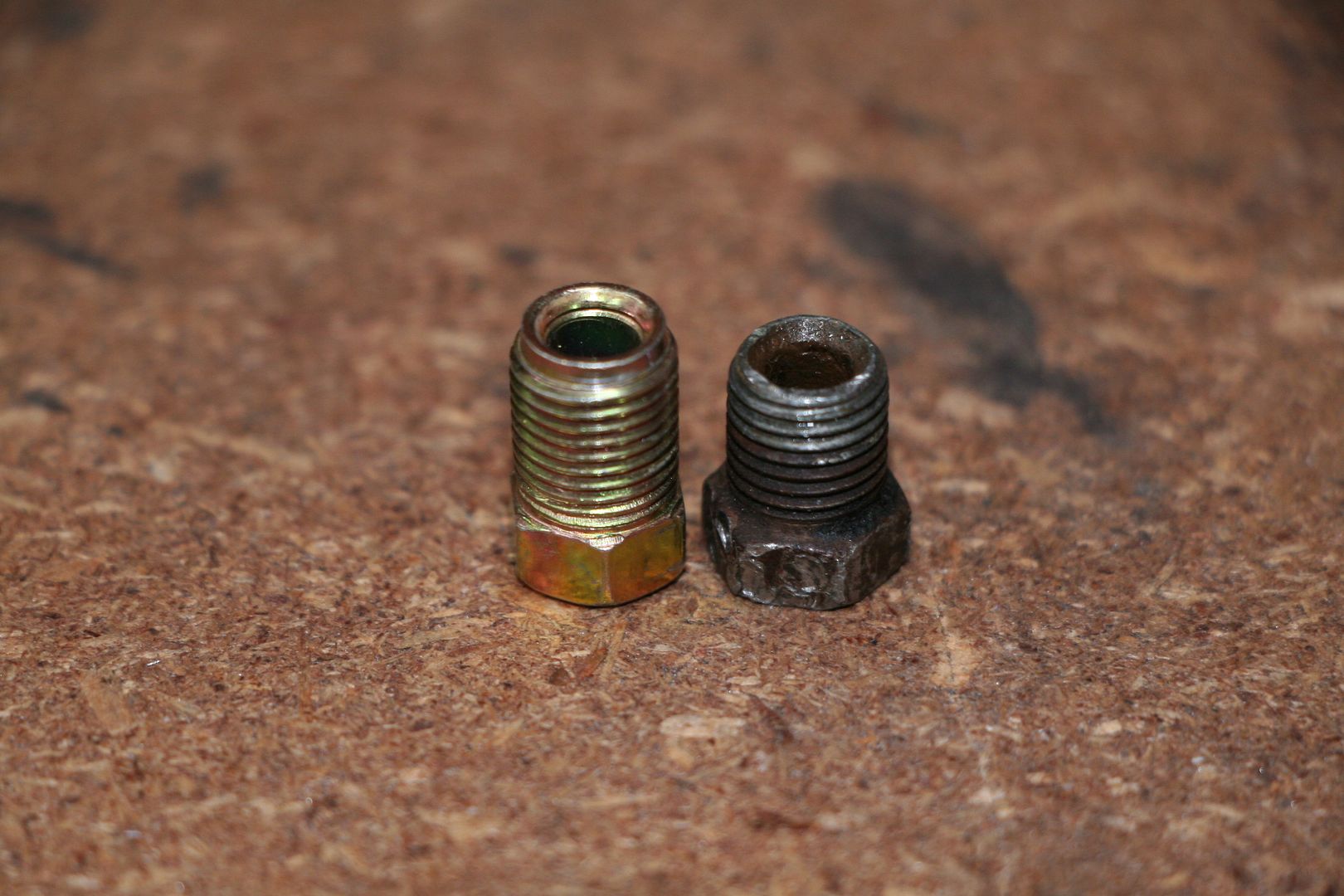
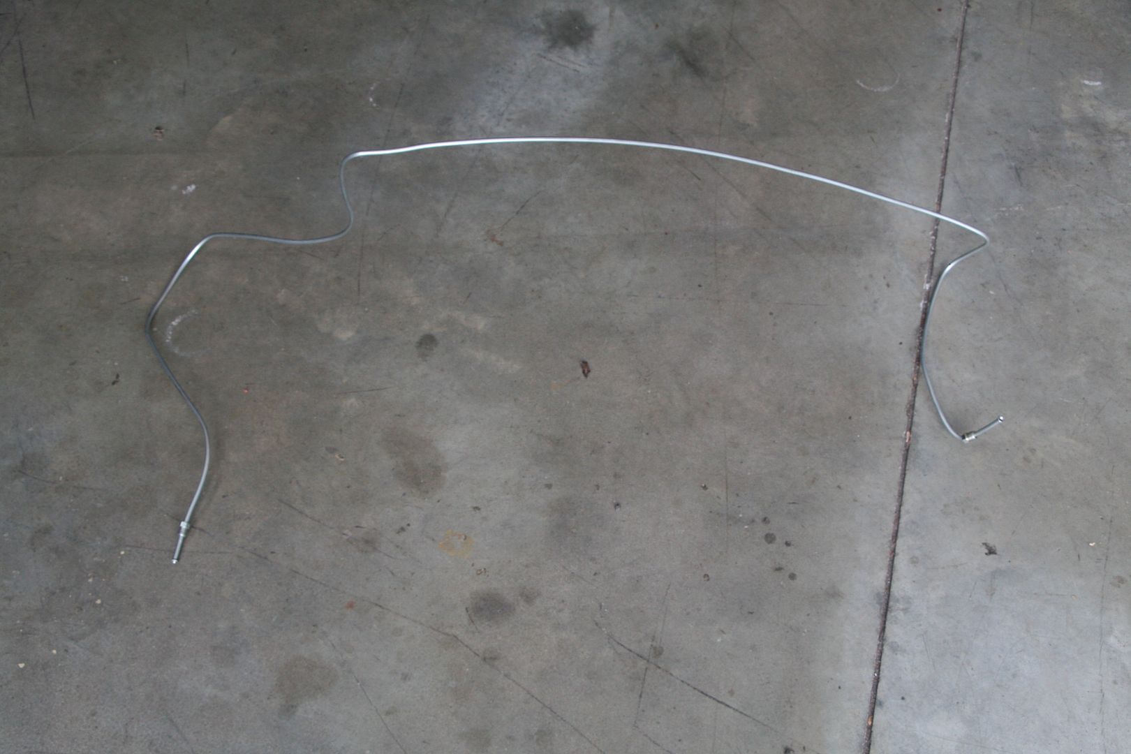
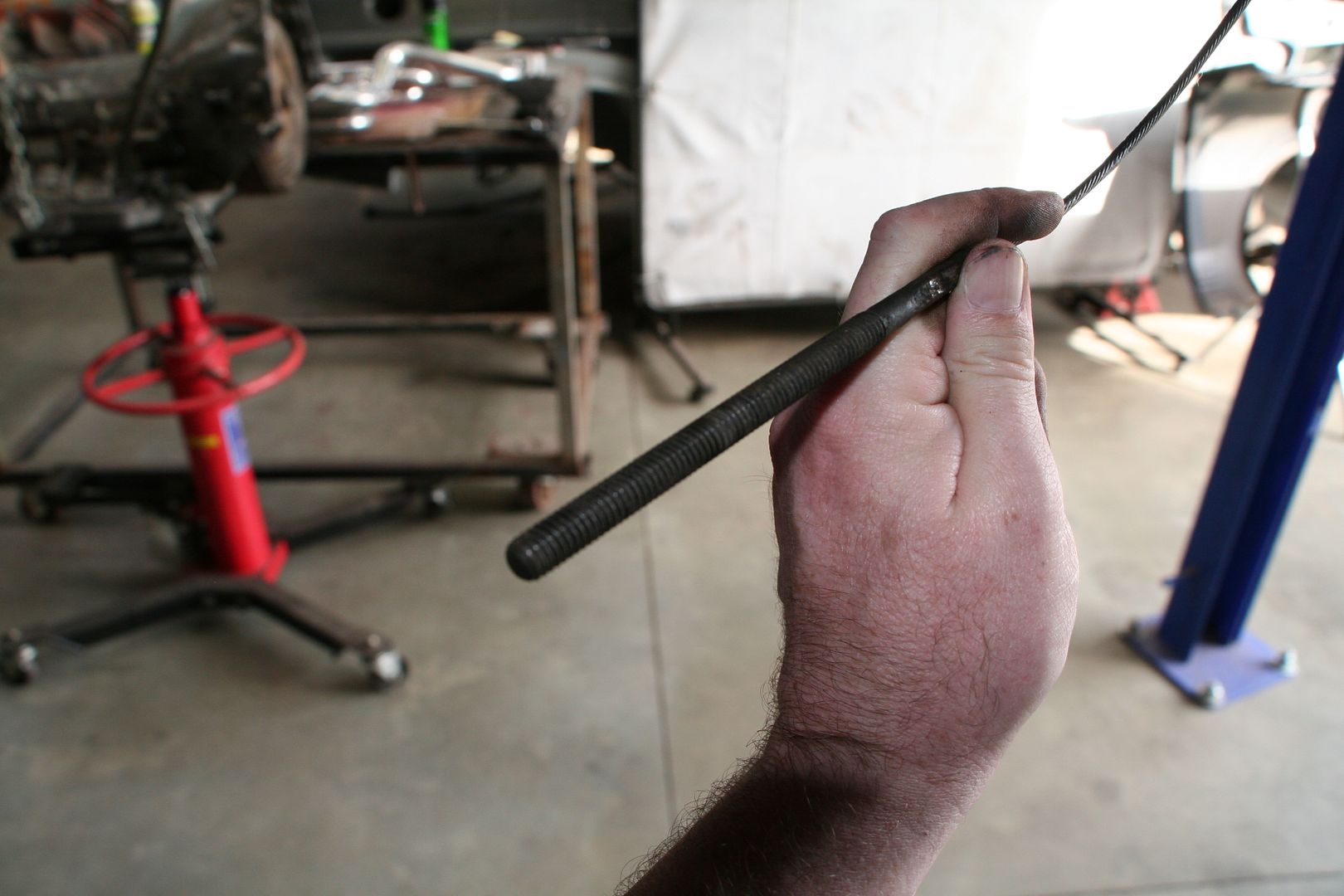
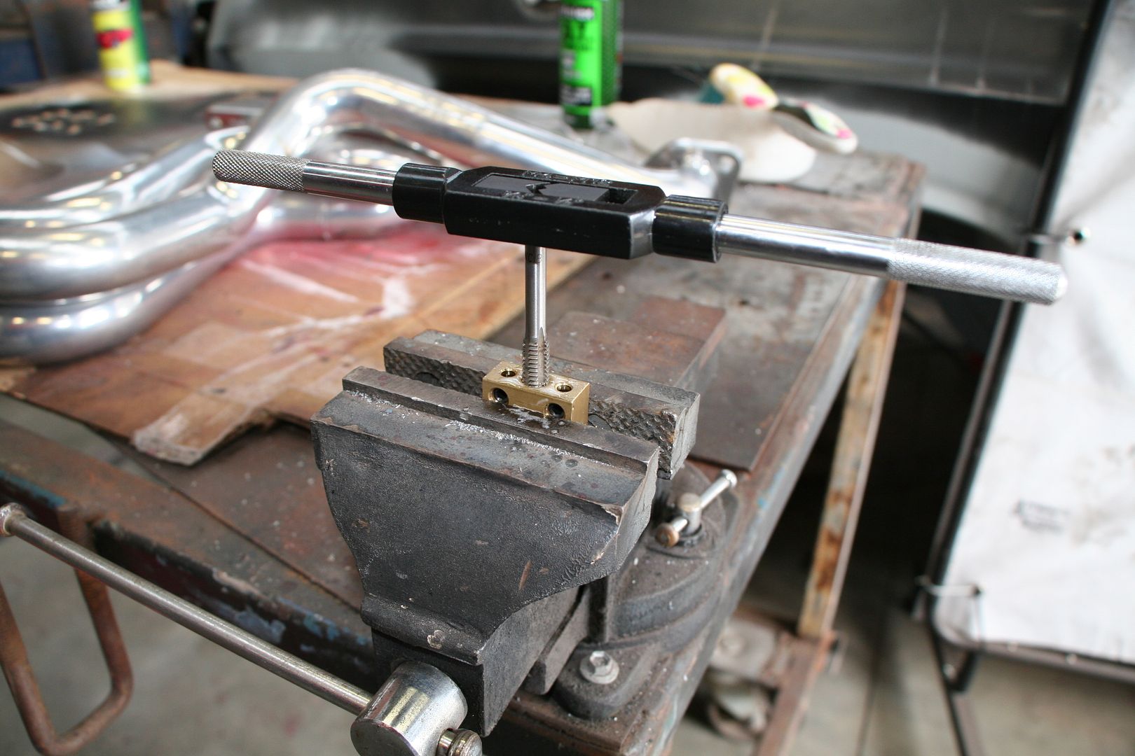
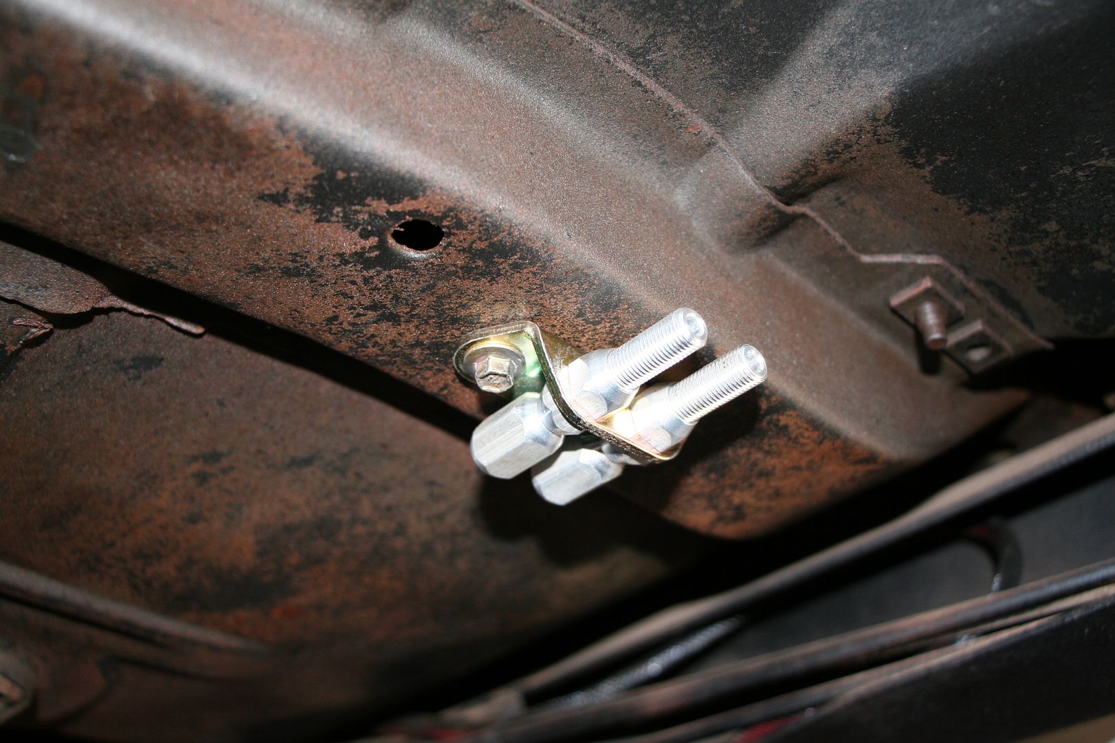
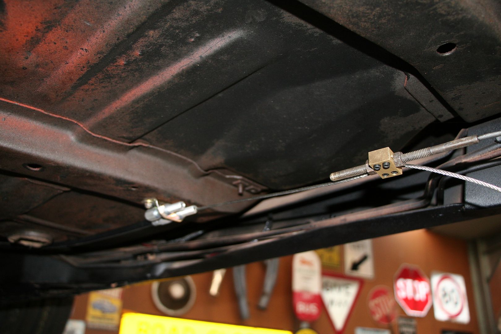
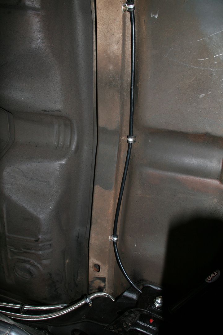
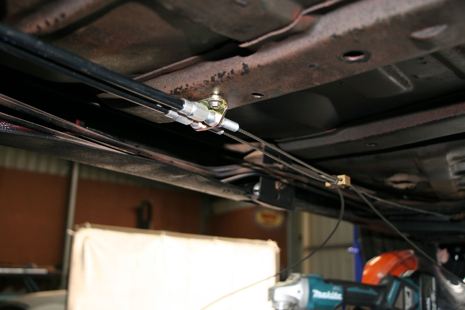
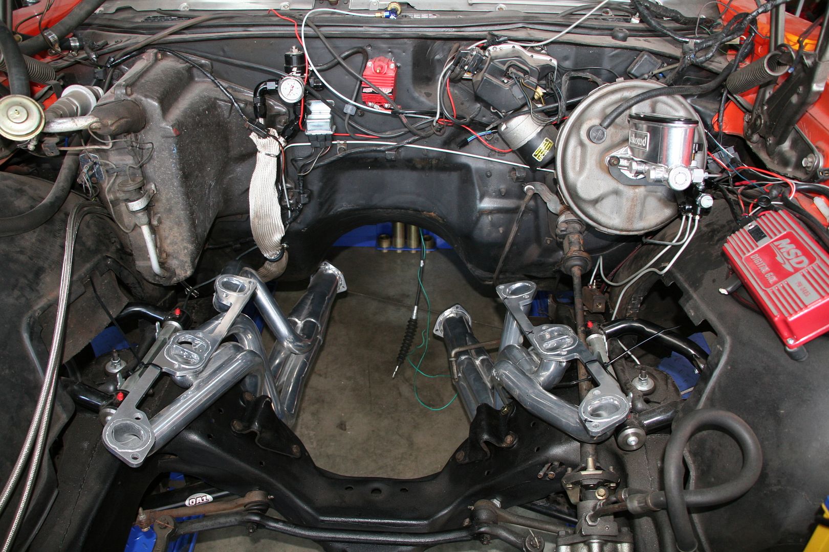
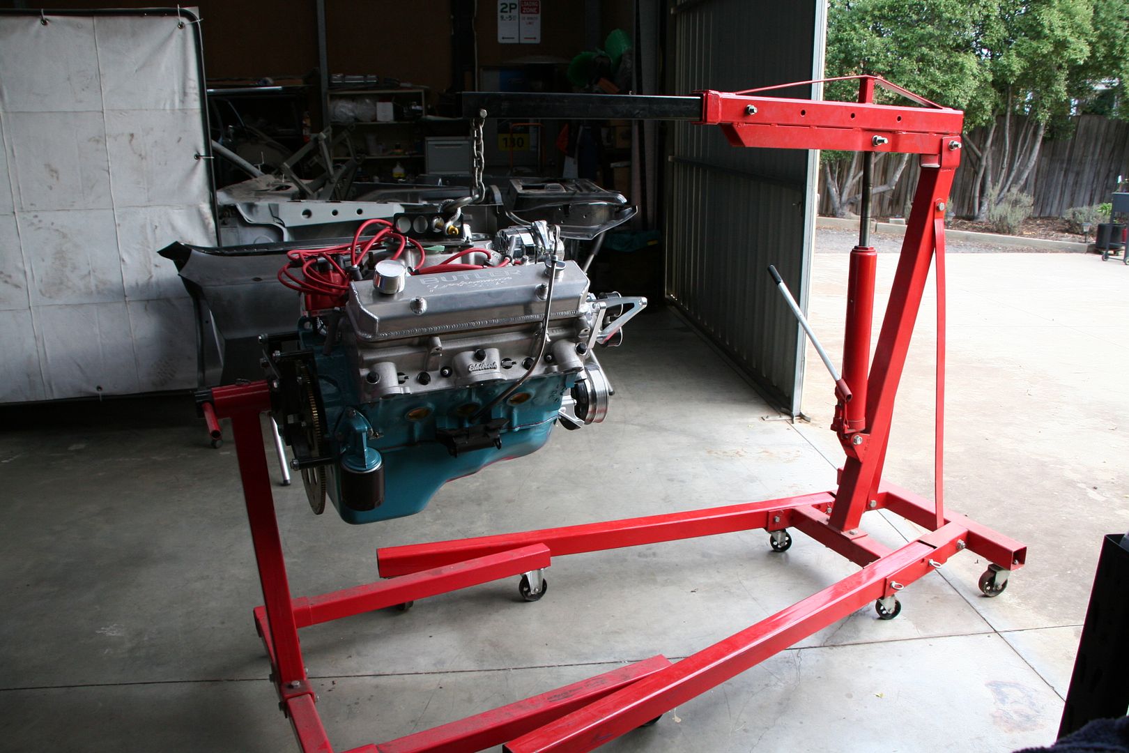
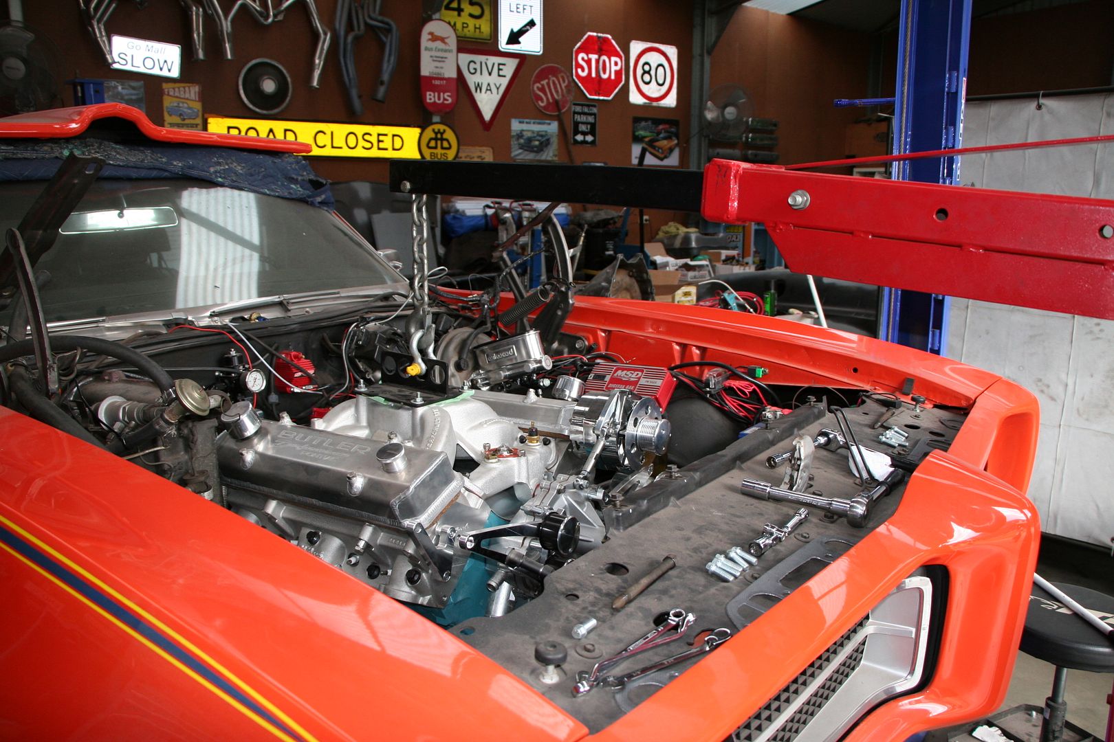
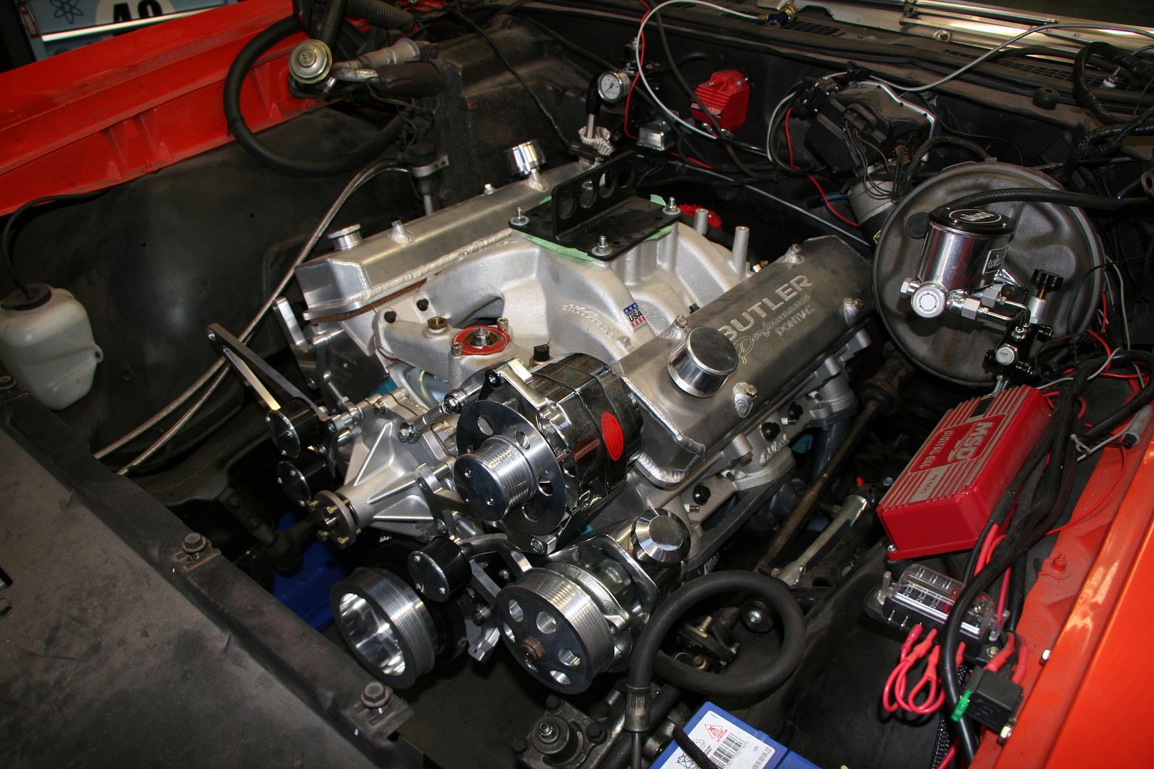
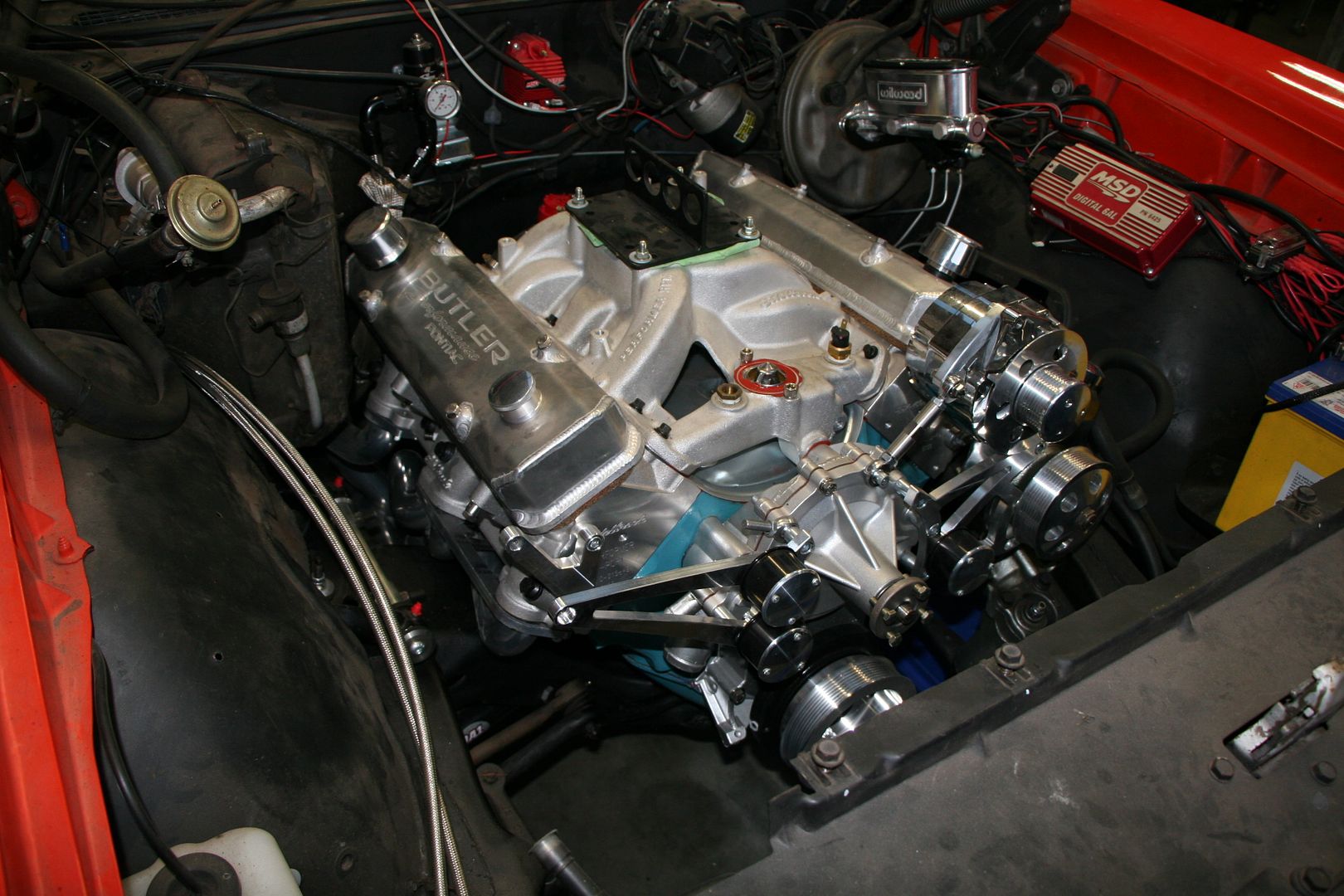
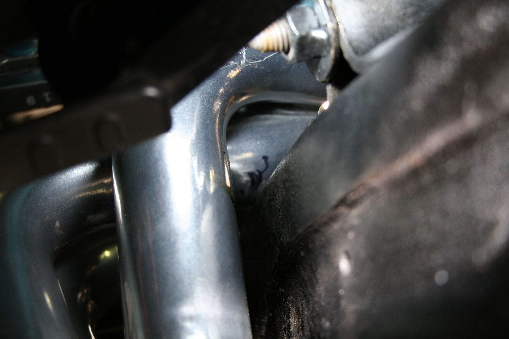
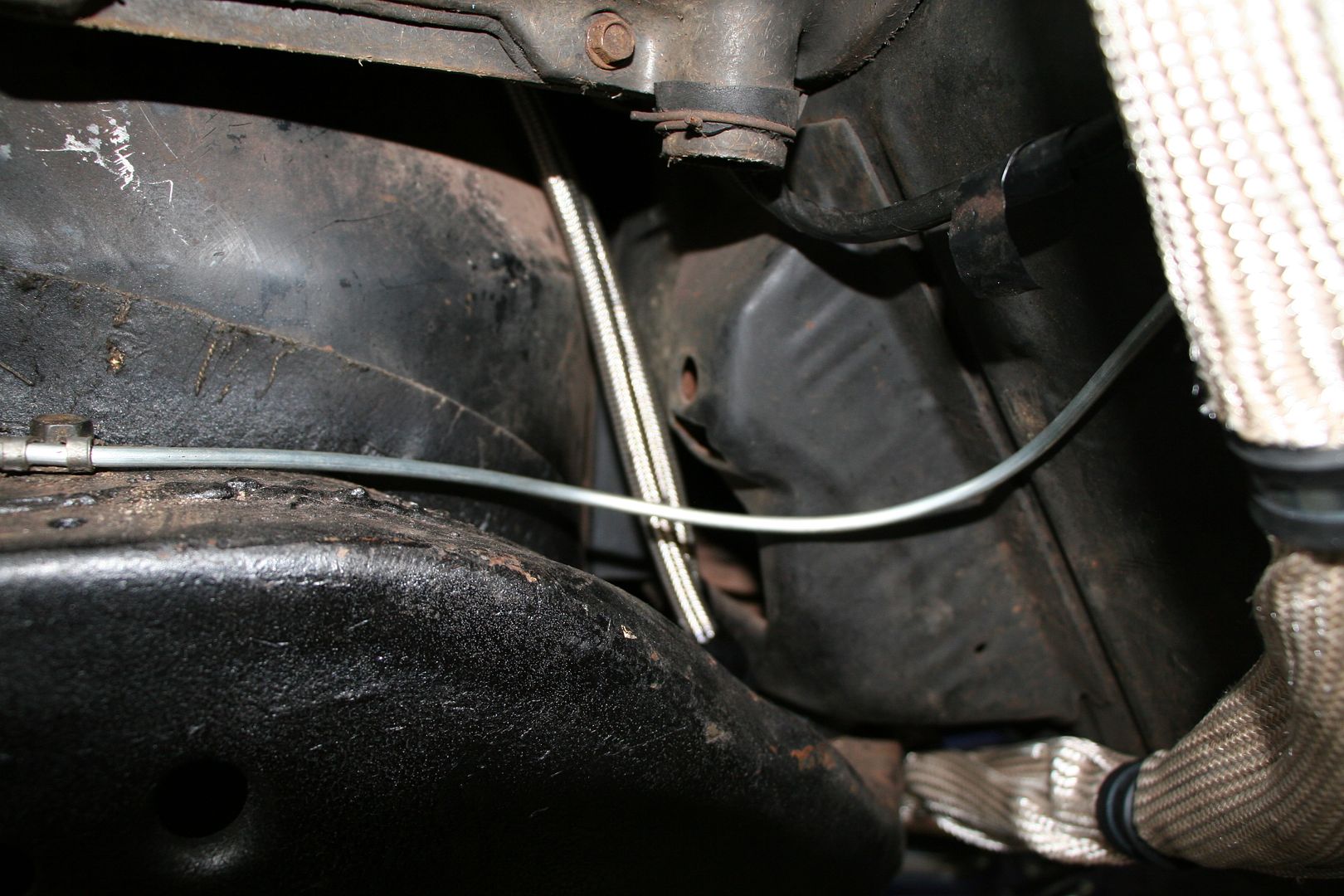
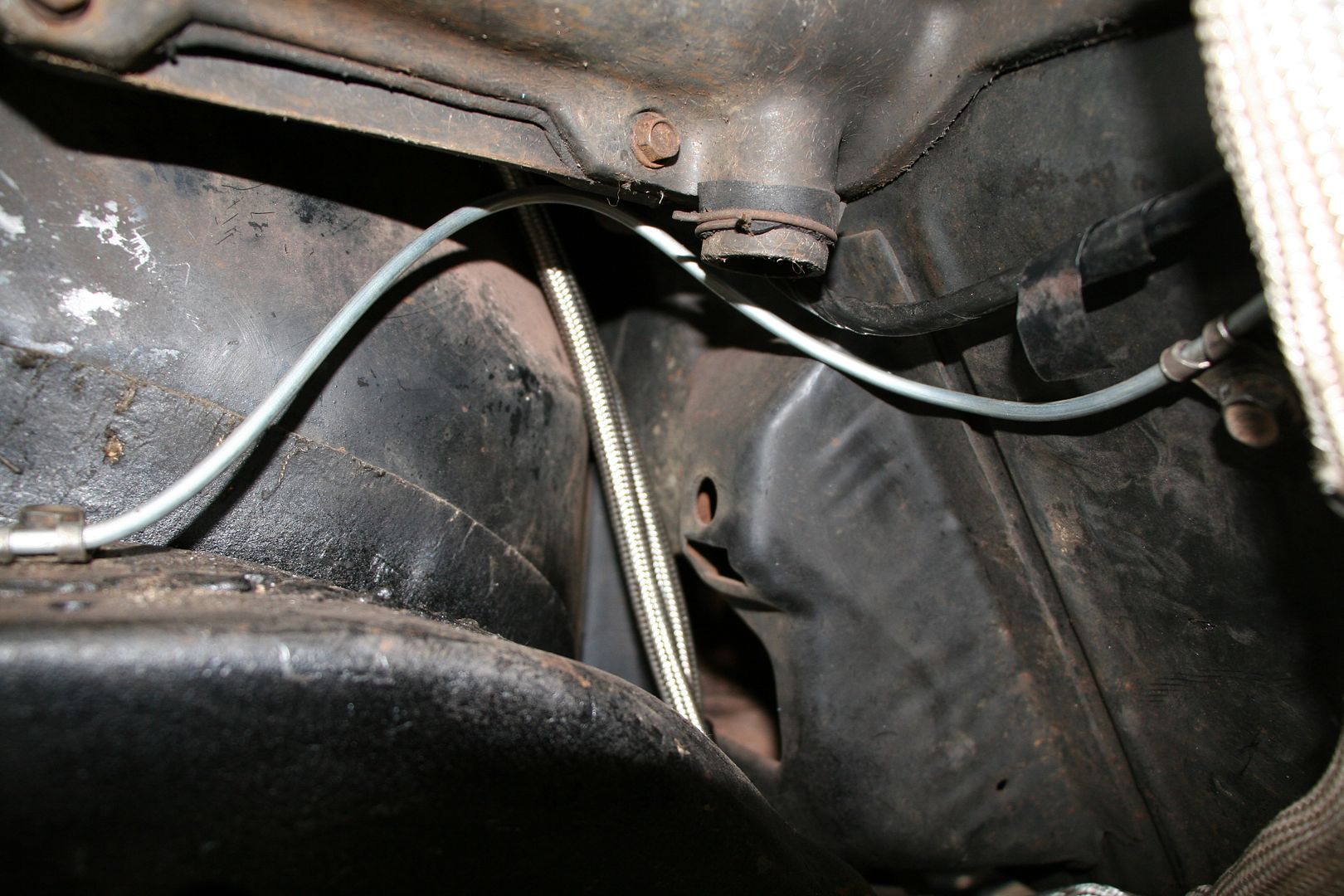
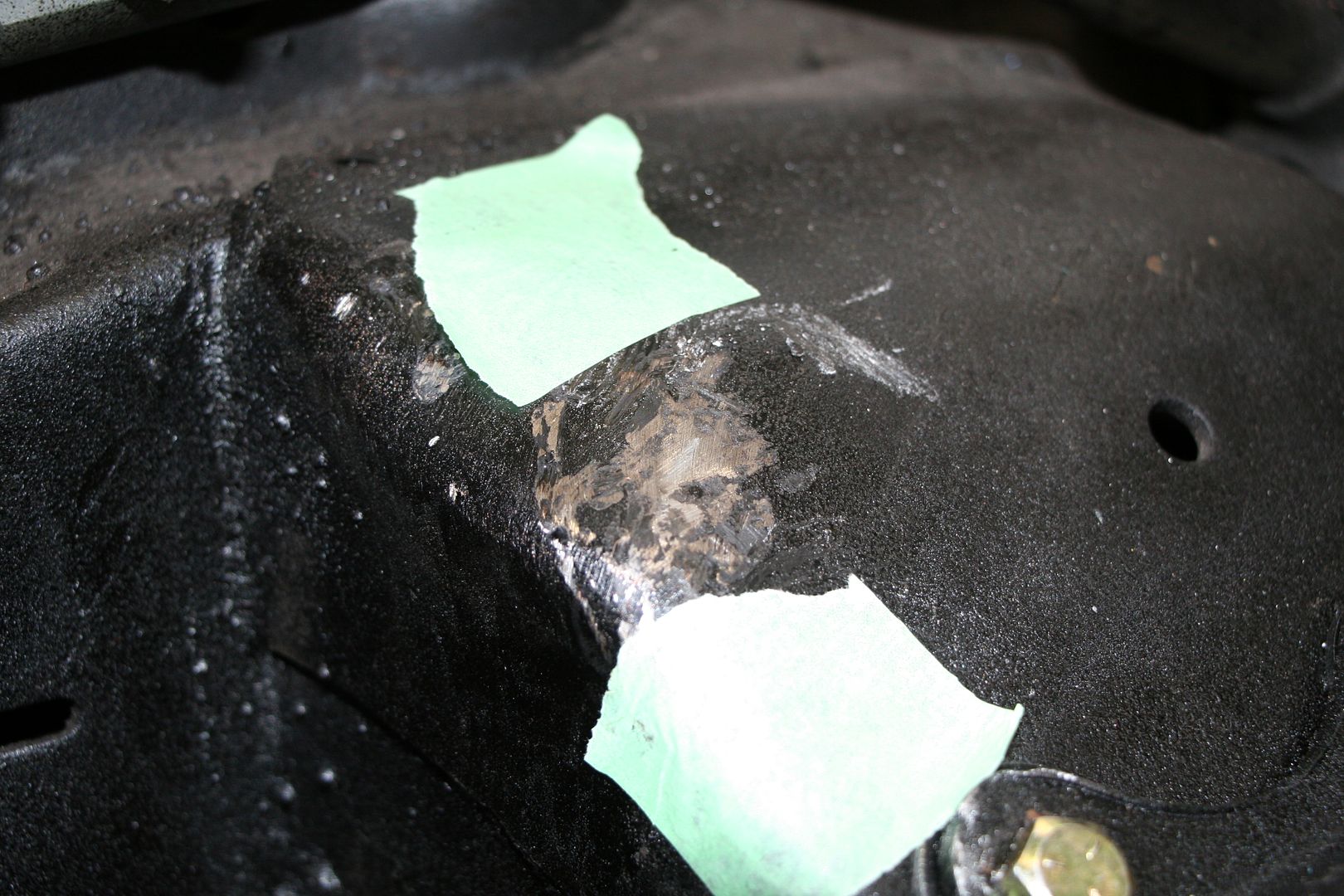
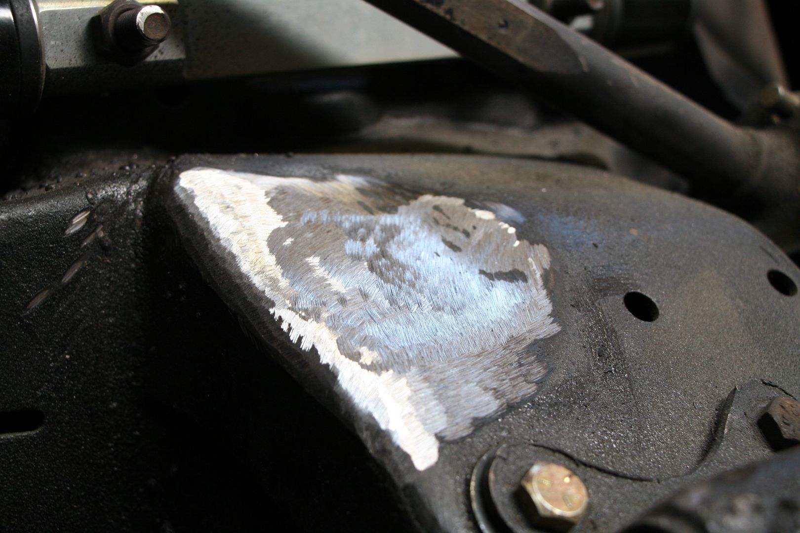
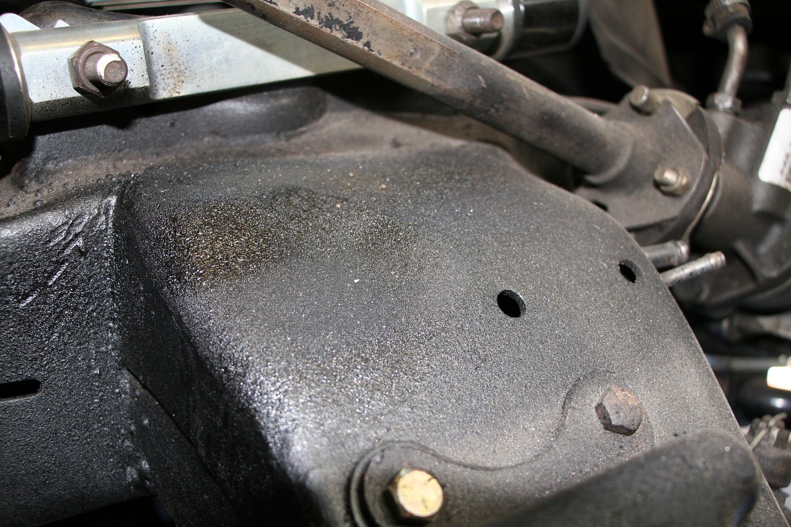
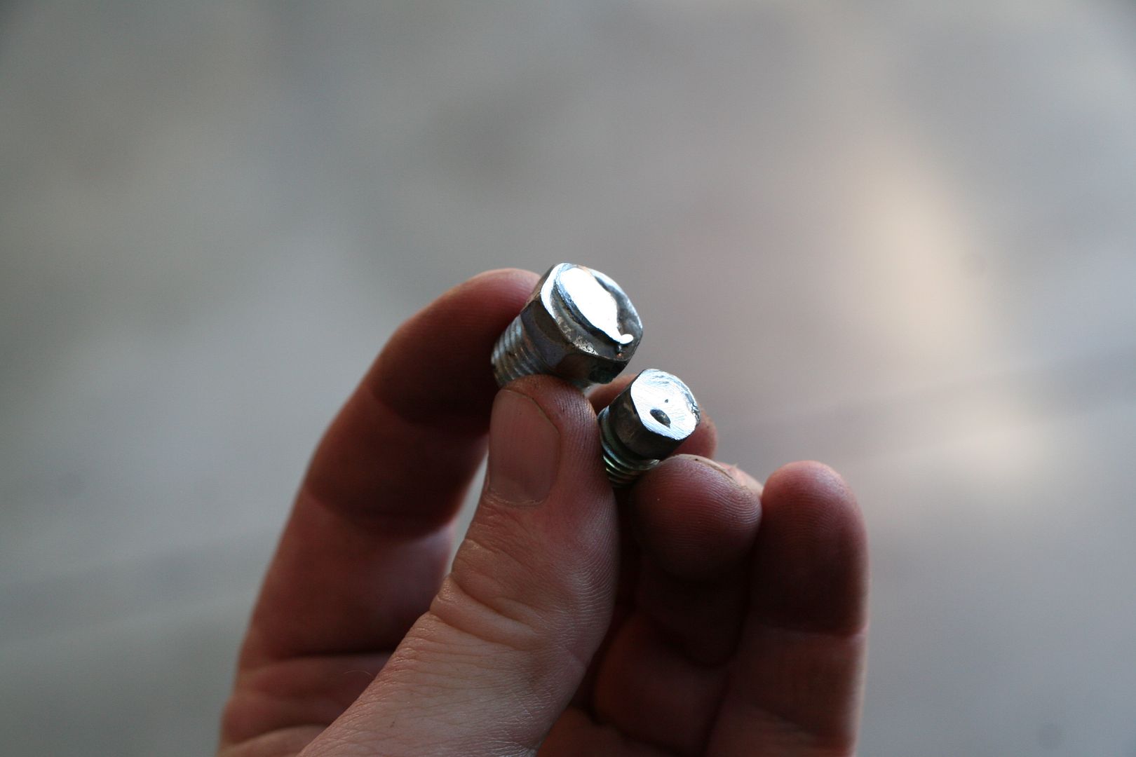
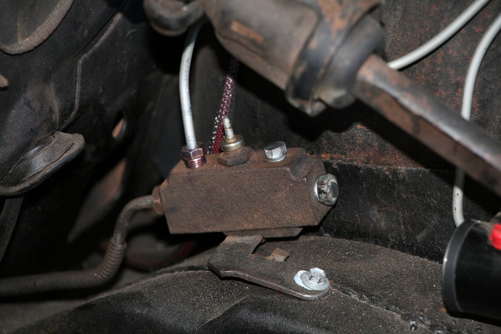
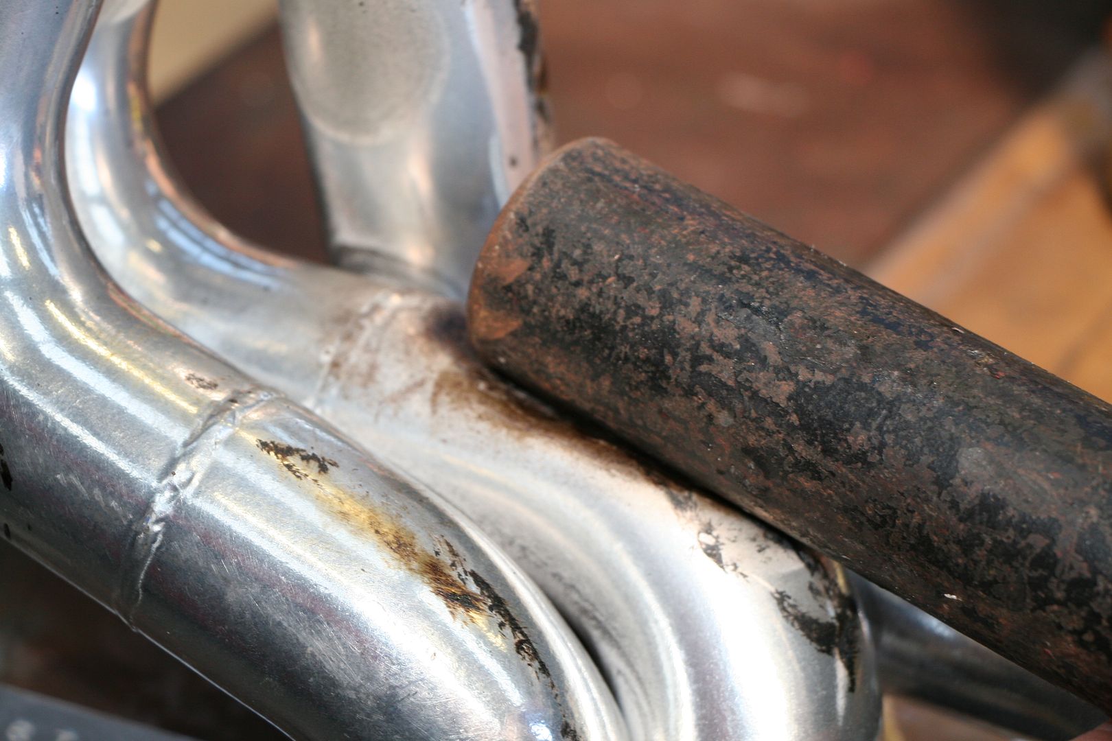
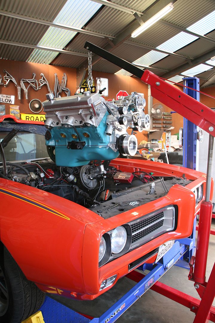
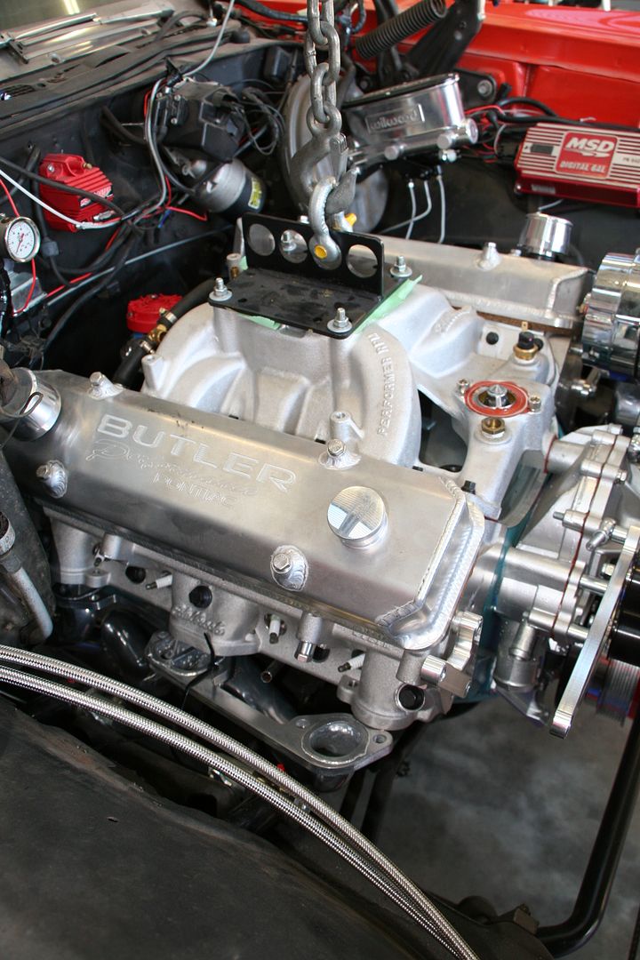
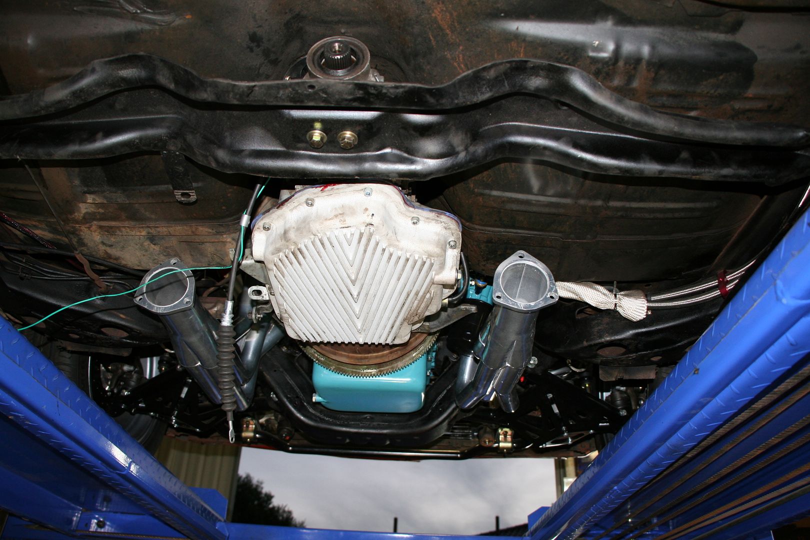
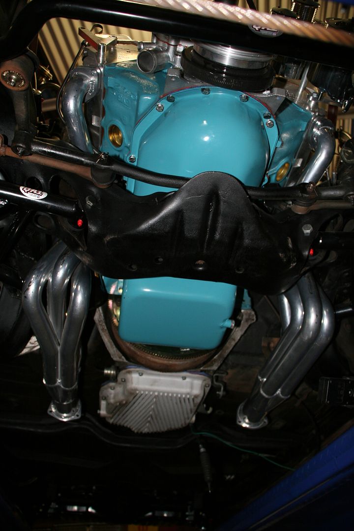
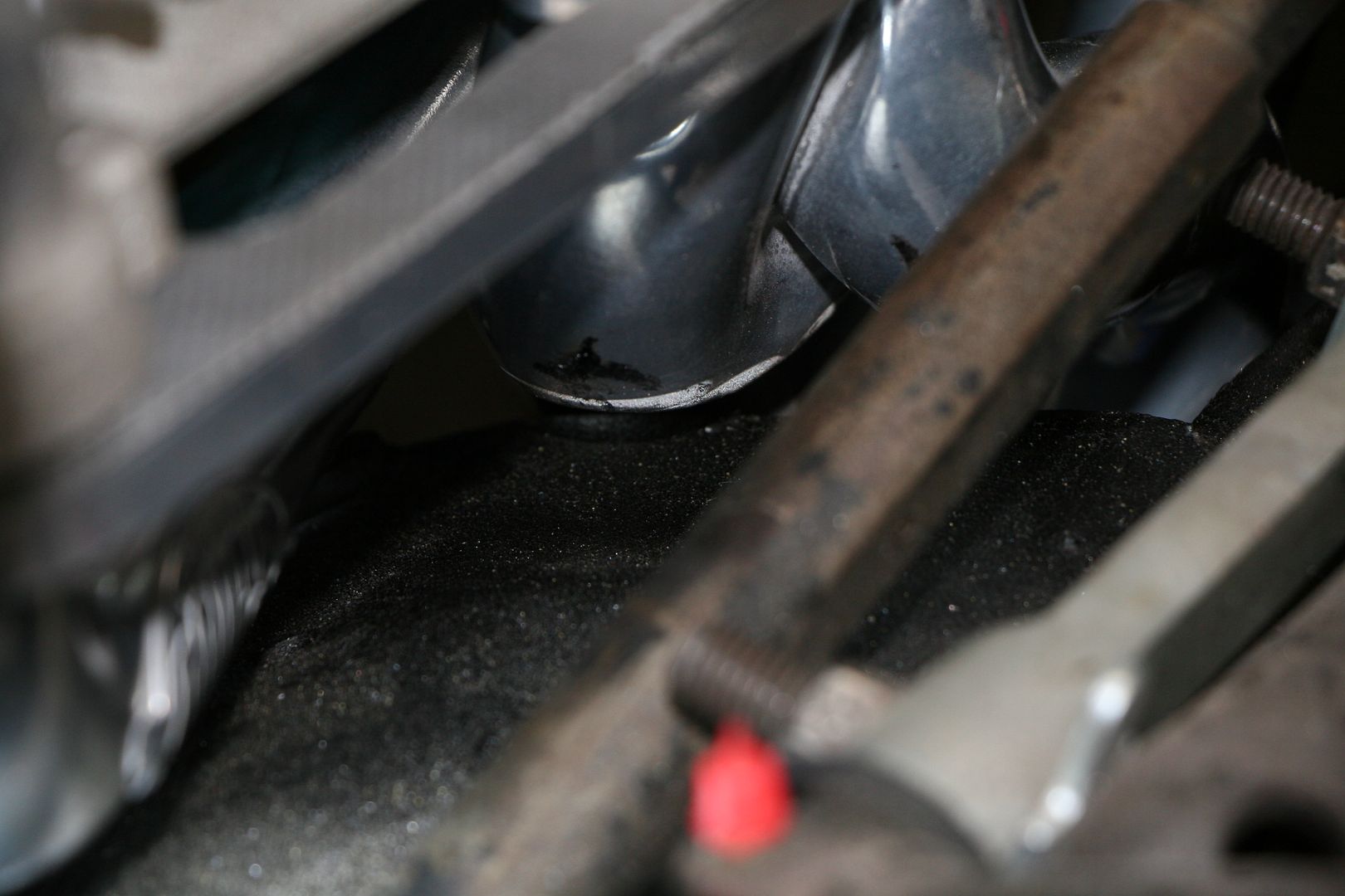
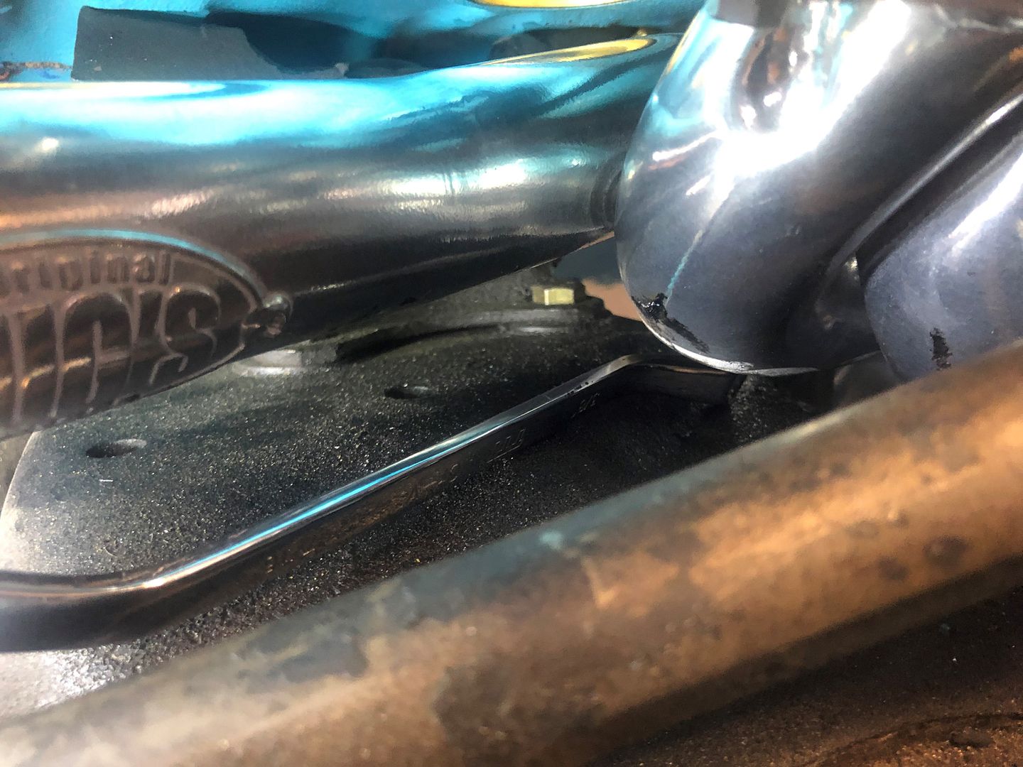
Here comes the Judge, my 69 GTO

13

Comments

  • Registered Users, Registered Users 2 Posts: 1,273 ✭✭✭Daved_XB


    I have driven it to work before, but I don't like driving it in Melbourne rush hour traffic as there are a LOT of muppet drivers out there & I normally see 2-3 crashes a day on a drive in & out of work & don't need this car rear ended if I can help it..... also I have to get out of the car & walk around to the carpark boom gate to get my ticket & that's a bit of a pain in the arse too


  • Registered Users, Registered Users 2 Posts: 1,428 ✭✭✭quietsailor


    Daved_XB wrote: »
    I have driven it to work before, but I don't like driving it in Melbourne rush hour traffic as there are a LOT of muppet drivers out there & I normally see 2-3 crashes a day on a drive in & out of work & don't need this car rear ended if I can help it..... also I have to get out of the car & walk around to the carpark boom gate to get my ticket & that's a bit of a pain in the arse too

    a couple of crashes a day!!! what kind of loons are you driving amongst


  • Registered Users, Registered Users 2 Posts: 1,273 ✭✭✭Daved_XB


    a couple of crashes a day!!! what kind of loons are you driving amongst

    Sadly driving standards here are really bad... last year we had 39,404 road deaths & over 4.4M people where injured badly enough to require medical attention... not sure on how big the number would be if you counted the folks who where in a crash but didn't need or didn't seek medical attention


  • Registered Users, Registered Users 2 Posts: 1,428 ✭✭✭quietsailor


    Daved_XB wrote: »
    Sadly driving standards here are really bad... last year we had 39,404 road deaths & over 4.4M people where injured badly enough to require medical attention... not sure on how big the number would be if you counted the folks who where in a crash but didn't need or didn't seek medical attention

    Yep, definitely a reason not to be bringing your pride & joy carefully restored car to work. I'd be commuting in a Mad-Maxesque truck myself :eek:


  • Registered Users, Registered Users 2 Posts: 741 ✭✭✭WildWater


    Daved_XB wrote: »
    Sadly driving standards here are really bad... last year we had 39,404 road deaths & over 4.4M people where injured badly enough to require medical attention... not sure on how big the number would be if you counted the folks who where in a crash but didn't need or didn't seek medical attention

    39,404 road deaths didn’t seem anywhere near right to me so I looked it up and according to Wikipedia it was 1,194.

    https://en.wikipedia.org/wiki/List_of_motor_vehicle_deaths_in_Australia_by_year

    Love your threads BTW


  • Registered Users, Registered Users 2 Posts: 1,273 ✭✭✭Daved_XB


    WildWater wrote: »
    39,404 road deaths didn’t seem anywhere near right to me so I looked it up and according to Wikipedia it was 1,194.

    https://en.wikipedia.org/wiki/List_of_motor_vehicle_deaths_in_Australia_by_year

    Love your threads BTW

    sorry... that was a typo... the link I was looking at gave that as the number of serious car crashes not deaths


  • Registered Users, Registered Users 2 Posts: 1,273 ✭✭✭Daved_XB


    Just a quick update to this thread… Melbourne has been in some pretty draconian lockdown for the last 8-10 weeks due to our second wave of ****e virus fun… they started to ease this somewhat last week & that meant that the engineering shop that was flow benching my cylinder heads was open again so we could get them back as they had been prisoners as the shop wasn’t allowed to open up by law…. Anyway lets not focus on the months lost… porting of both of my heads is finished now

    IMG_9673.JPG?width=1920&height=1080&fit=bounds

    IMG_9672.JPG?width=1920&height=1080&fit=bounds

    IMG_9671.JPG?width=1920&height=1080&fit=bounds

    Not only that both heads are on the engine now…

    IMG_9670.JPG?width=1920&height=1080&fit=bounds

    IMG_9668.JPG?width=1920&height=1080&fit=bounds

    Along with the whole valve train being finished

    IMG_9669.JPG?width=590&height=370&fit=bounds

    Intake & valve covers are on….

    IMG_9674.JPG?width=1920&height=1080&fit=bounds

    In fact it’s pretty much done… there are one or two tiny details like the oil filter housing that we need to reuse needs to be cleaned & painted & installed etc.. but all things being equal I should have the engine back in my shed in a week or so now

    IMG_9667.JPG?width=1920&height=1080&fit=bounds

    IMG_9666.JPG?width=1920&height=1080&fit=bounds

    Whilst I think it almost looks too good to be hidden in a car… I cannot wait to get back on to this car & get he out on the road ASAP…


  • Registered Users, Registered Users 2 Posts: 1,273 ✭✭✭Daved_XB


    This got delivered to me today… it looks so good in the metal, tomorrow as going to be more work on the XB but change of plans now…. This is going into the GTO now instead

    IMG_9718.jpg?width=1920&height=1080&fit=bounds

    IMG_9717.jpg?width=1920&height=1080&fit=bounds

    It’s been out so long now that I’m sure I will have a **** of a time finding all of the bolts & bits that I took off, but for now I think I know where the new engine mounts are so I should be able to get the engine back in the bay as a minimum…


  • Registered Users, Registered Users 2 Posts: 1,428 ✭✭✭quietsailor


    Daved_XB wrote: »
    This got delivered to me today… it looks so good in the metal, tomorrow as going to be more work on the XB but change of plans now…. This is going into the GTO now instead

    It’s been out so long now that I’m sure I will have a **** of a time finding all of the bolts & bits that I took off, but for now I think I know where the new engine mounts are so I should be able to get the engine back in the bay as a minimum…

    You'll just have to buy new bolts & bits for it ;):p:p:p


  • Registered Users, Registered Users 2 Posts: 1,273 ✭✭✭Daved_XB


    Turns out I have a full ARP bolt kit for the engine already…

    IMG_8966.JPG?width=1920&height=1080&fit=bounds

    The bolts that came with the engine kit from Butler are all silver so I’ll swap some of them out for the nicer looking black ARP stuff…. Because… well because reasons

    IMG_8955.JPG?width=1920&height=1080&fit=bounds

    IMG_8956.JPG?width=1920&height=1080&fit=bounds

    I also have some shiny bling to dress up the front of the engine

    IMG_8957.JPG?width=1920&height=1080&fit=bounds

    Bolted on the new engine mounts… remember this little bugger… this will be the death of me (spoiler alert)

    IMG_8958.JPG?width=1920&height=1080&fit=bounds

    Then with the help of Mrs_XB we lifted the engine up 7 dropped it into the engine bay..

    IMG_8962.JPG?width=1920&height=1080&fit=bounds

    IMG_8961.JPG?width=1920&height=1080&fit=bounds

    IMG_8959.JPG?width=1920&height=1080&fit=bounds

    As soon as it was in I commented to Mrs_XB that there was no ****ing way I could see me getting the passenger side exhaust header installed, there is **** all gap between the chassis rail & the heads & the oil filter & the oil filter adapter is in the way

    IMG_8960.JPG?width=1920&height=1080&fit=bounds

    The drivers side fouled badly on that engine mount & there was just no way to get this on… I could get so so close but no way it would go on

    IMG_8964.JPG?width=1920&height=1080&fit=bounds


  • Advertisement
  • Registered Users, Registered Users 2 Posts: 1,273 ✭✭✭Daved_XB


    So out the engine came again & I test fitted the headers to the engine to see if I could work out the best way to do the install

    IMG_8969.JPG?width=1920&height=1080&fit=bounds

    I could see where it was fouling on the safety tab of the mount, so I trimmed it off, leaving as much of the tab as I could….

    IMG_8973.JPG?width=1920&height=1080&fit=bounds

    IMG_8968.JPG?width=1920&height=1080&fit=bounds

    I really don’t want to remove the oil filter & it’s housing, but you can see how it would be impossible to install the header with them in place

    IMG_8971.JPG?width=1920&height=1080&fit=bounds

    IMG_8970.JPG?width=1920&height=1080&fit=bounds

    I decided to fit that header up & to use my engine leveler to see if I could tilt the engine in with that one header pre-installed

    IMG_8979.JPG?width=1920&height=1080&fit=bounds

    IMG_8978.JPG?width=1920&height=1080&fit=bounds

    Mrs_XB & I spent a full 30 minutes struggling with this & the short answer is no…. there was no way it was going to fit… so out it came again so I could remove the filter housing

    IMG_8981.JPG?width=1920&height=1080&fit=bounds

    IMG_8980.JPG?width=1920&height=1080&fit=bounds


  • Registered Users, Registered Users 2 Posts: 1,273 ✭✭✭Daved_XB


    So going with the old 3rd times a charm I ended up suspending the engine in the engine bay but raised up about 2-3”

    IMG_8982.JPG?width=1920&height=1080&fit=bounds

    This allowed me to finally get the headers to fit in… the issue is that the mounting face angle of Pontiac heads are much more downward facing that Ford, Mopar or Chev heads so you have so much less space to play with

    IMG_8986.JPG?width=1920&height=1080&fit=bounds

    IMG_8985.JPG?width=1920&height=1080&fit=bounds

    IMG_8984.JPG?width=1920&height=1080&fit=bounds

    IMG_8983.JPG?width=1920&height=1080&fit=bounds

    Now looking at the pics above you can see that there is very very little space between the headers & the chassis rails… but this is because the gearbox isn’t on yet & once that is on & the rear of the box is on its crossmember then it tilt the engine forward & give more space

    IMG_8989.JPG?width=1920&height=1080&fit=bounds

    So after a long & frustrating day in the shed I was very happy to have this finally sitting in the bay

    IMG_8987.JPG?width=1920&height=1080&fit=bounds

    IMG_8988.JPG?width=1920&height=1080&fit=bounds


  • Registered Users, Registered Users 2 Posts: 3,426 ✭✭✭KaneToad


    I know virtually nothing about cars or engines and would consider myself as having little interest in them.

    But...

    I've just read this entire thread and am fascinated! Great work, and thanks for sharing.


  • Registered Users, Registered Users 2 Posts: 1,273 ✭✭✭Daved_XB


    KaneToad wrote: »
    I know virtually nothing about cars or engines and would consider myself as having little interest in them.

    But...

    I've just read this entire thread and am fascinated! Great work, and thanks for sharing.

    Thanks... glad you enjoyed it. If you really want to go down the rabbit hole, check out my other build threads in this section... this one is the smallest & probably least impressive IMHO.


  • Registered Users, Registered Users 2 Posts: 1,428 ✭✭✭quietsailor


    That was epic, you have wayyyyy more patience than I have!


  • Registered Users, Registered Users 2 Posts: 1,273 ✭✭✭Daved_XB


    I got myself full serpentine kit for the accessories from CVF racing, I went the chrome option rather than the black that they also offer… I’ve used a lot of their brackets before as they are just great quality… this kit is the full Alt/PS/AC kit as I hope to reinstall the AC function to this car too.

    The Alt & Power Steering both hang off the same side so it’s just one big bracket on the driver’s side for that

    IMG_9038.JPG?width=1920&height=1080&fit=bounds

    My chrome Alt can be reused here but I need to swap out the original V belt pulley & the original fan too as this fouls on the bracket.. CVF supply a replacement fan that won’t foul

    IMG_9039.JPG?width=1920&height=1080&fit=bounds

    So off with the old fan & pulley

    IMG_9040.JPG?width=1920&height=1080&fit=bounds

    Then install this lovely billet fan piece & mount up the Alt

    IMG_9041.JPG?width=1920&height=1080&fit=bounds

    IMG_9042.JPG?width=1920&height=1080&fit=bounds

    The brackets mount he power steering pump about 2 inches offset from the factory mounting… hopefully this doesn’t need mean I need to make up new hi & low pressure lines but that’s a future Dave issue

    IMG_9044.JPG?width=1920&height=1080&fit=bounds

    IMG_9043.JPG?width=1920&height=1080&fit=bounds

    Then install the pulley onto the pump & install the black belt routing pulley

    IMG_9045.JPG?width=1920&height=1080&fit=bounds

    Then I installed the AC bracket & the other two routing pulleys

    IMG_9047.JPG?width=1920&height=1080&fit=bounds

    IMG_9046.JPG?width=1920&height=1080&fit=bounds

    That’s when the fun ended…. Turns out that the bracket kit from CVF can’t be used with the original factory style AC compressor…. Which is a big shame as I have a new shiny chrome one here that I ordered way back when I first bought the car.. guess it’s a show paper weight now

    IMG_9049.JPG?width=1920&height=1080&fit=bounds

    I’ve ordered the correct one from CVF now tonight & a good thing I guess is that it’s a more modern item & it’s less than half the length & half the weight of the original design so I guess that’s a good thing.. just hope the Covid shipping times from the US aren’t too bad….

    IMG_9048.JPG?width=1920&height=1080&fit=bounds

    So this is how the engine sits now… next up I’ll work on some of the wiring & installing the modern MSD ignition system whilst I await the parts


  • Registered Users, Registered Users 2 Posts: 1,273 ✭✭✭Daved_XB


    This update will be a bit all over the place as I was working with no real plan on the weekend & bounced all over the place because of this & also because of my probable ADH… look a squirrel…

    I thought I’d test fit the new mini hi-torque starter that I got with the engine kit, it’s tiny!! I have no idea how this thing has more torque than the old outgoing starter has…. But I suspect its something to do with Aliens from Area 51.

    IMG_9050.JPG?width=1920&height=1080&fit=bounds

    There is heaps of room for this mini starter here, I held up the old one to the same spot & it would have been right on the headers.. so the mini starter was a great idea

    IMG_9053.JPG?width=1920&height=1080&fit=bounds

    IMG_9052.JPG?width=1920&height=1080&fit=bounds

    IMG_9051.JPG?width=1920&height=1080&fit=bounds

    Now the wiring will be a little different for this new starter, the main post is on the opposite side to the original so when the cable is connected to the starter it no longer reaches the battery.. so I’ll make up some new leads for that with new post connectors too

    IMG_9056.JPG?width=1920&height=1080&fit=bounds

    The original heat protection tube that shields the starter wires as they pass the exhaust looks like it can be reused, just need to make a bracket to hold it

    IMG_9057.JPG?width=1920&height=1080&fit=bounds

    The wiring instructions for this new starter aren’t really clear to me & to be honest that may just be the fact that I don’t really understand wiring… if I’m halfarsed in most things I do on these cars I’m fully zeroarsed with wiring, as an example I don’t fully understand why when I unplug something from the wall socket without switching the wall socket off why doesn’t electricity pour out onto the floor? I do however know enough to fully understand the smoke law which states (I’m paraphrasing here) once the smoke exits the wires or the device it’s impossible to get the smoke back in… so I’ll have to do some Dr Google research & maybe even open the GTO service & repair manuals I bought & do some reading before I hook up wires & test fire anything… the last thing I want to do is to send 12.6V to something or through something that really didn’t want 12.6V.. so I’ll be learning all about relays & switched power wires etc…

    I had been thinking that I’d need to paint the gearbox before reinstalling it… but some elbow grease, some actual degreaser & a wire wheel & it looks great.. so this is ready to go back in

    IMG_9063.JPG?width=1920&height=1080&fit=bounds

    IMG_9062.JPG?width=1920&height=1080&fit=bounds

    Before reinstalling the trans I’ve taken the time to set up the oil senders, the car has an idiot light in the dash that comes on where there is zero oil pressure.. I had fitted an aftermarket mechanical gauge inside the car a good while back but I’d never gotten around to connecting it… so now I have made up a set of adapters that allow me to connect the mechanical end into the top of the blue T piece & the original idiot light sensor to the end so in theory I now have a live feed of oil pressure & in your line of sight idiot light for when I’m not looking at the gauge

    IMG_9054.JPG?width=1920&height=1080&fit=bounds

    I was pleasantly surprised that the new correct AC compressor that I ordered on Tuesday night out of the US turned up here midday Sunday…. It’s very shiny, much chromes

    IMG_9072.JPG?width=1920&height=1080&fit=bounds


  • Registered Users, Registered Users 2 Posts: 1,273 ✭✭✭Daved_XB


    It’s a lot smaller than the original one I have… but to be honest it feels a little heavier

    IMG_9077.JPG?width=1920&height=1080&fit=bounds

    It bolts up nicely

    IMG_9078.JPG?width=1920&height=1080&fit=bounds

    & with the added chrome front cover.. that alone must be worth 7HP

    IMG_9080.JPG?width=1920&height=1080&fit=bounds

    I decided to test fit the belt & set the tension etc before I installed the fan blades… as there is feck all clearance to get the fan on to this car with the radiator & the fan shroud… so best to test the fit out in the open first

    IMG_9079.JPG?width=1920&height=1080&fit=bounds

    The fuel inlet side of my new Holley 850 double pumper Crab is on the opposite side of the Crab that the old set up I had, so I’ve had to move the fuel regulator so that the lines will be more aligned

    IMG_9067.JPG?width=1920&height=1080&fit=bounds

    Since my plan is to get the AC working on this car again, I’ve taken the pro-active approach to swap out the blower motor resistor & the AC relay, whilst there may be nothing wrong with these they were cheap & easy to swap out so I’m hoping that this aids in any troubleshooting going forward as to what parts work/don’t work

    IMG_9064.JPG?width=1920&height=1080&fit=bounds

    IMG_9066.JPG?width=1920&height=1080&fit=bounds

    IMG_9061.JPG?width=1920&height=1080&fit=bounds

    IMG_9058.JPG?width=1920&height=1080&fit=bounds

    IMG_9068.JPG?width=1920&height=1080&fit=bounds


  • Registered Users, Registered Users 2 Posts: 1,273 ✭✭✭Daved_XB


    Next up is the installation of my MSD ignition box

    IMG_9060.JPG?width=1920&height=1080&fit=bounds

    It sits on rubber isolators

    IMG_9059.JPG?width=1920&height=1080&fit=bounds

    Now I’ve got to map out the routing for the wiring & try & make that neat

    IMG_9070.JPG?width=1920&height=1080&fit=bounds

    IMG_9071.JPG?width=1920&height=1080&fit=bounds

    There is also a new MSD coil that needs to be wired in

    IMG_9081.JPG?width=1920&height=1080&fit=bounds

    I also need to sort my fan… the clutch in this clutch fan is failed

    IMG_9082.JPG?width=1920&height=1080&fit=bounds

    I have a brand new clutch to go on

    IMG_9083.JPG?width=1920&height=1080&fit=bounds

    Then I just cleaned up & painted the fan blades to make it all look a little better… at some pint I may switch across to thermo fans but for now this set up works fine

    IMG_9086.JPG?width=1920&height=1080&fit=bounds

    IMG_9085.JPG?width=1920&height=1080&fit=bounds


  • Advertisement
  • Registered Users, Registered Users 2 Posts: 1,273 ✭✭✭Daved_XB


    Dropped the radiator in & cable tied it in place as it’s the shroud that holds the rad in place

    IMG_9084.JPG?width=1920&height=1080&fit=bounds

    Then you have to very carefully lower in the fan assembly & the shroud at the same time as there is bugger all space

    IMG_9087.JPG?width=1920&height=1080&fit=bounds

    Then the trick is to slide your arm down & try & attach the fan to the water pump pully before the bleeding that has been induced by the top of the shroud cutting into your arm & the fan blade edges slicing your knuckles causes you to pass out… I just about managed to achieve this…

    IMG_9089.JPG?width=1920&height=1080&fit=bounds

    IMG_9088.JPG?width=1920&height=1080&fit=bounds

    The last step then is to fight the serpentine belt to get on over all the pulleys as even with everything adjusted to give the most slack it only just goes on by the tiniest of bees appendages

    IMG_9092.JPG?width=1920&height=1080&fit=bounds

    But it’s on… it’s all together & I think I have the tension set right… it was a pain in the arse to fit & it fought a lot along the way but I’m really happy with how it’s looking, I won’t be ashamed to open the bonnet at a C&C ever again

    IMG_9094.JPG?width=1920&height=1080&fit=bounds

    IMG_9093.JPG?width=1920&height=1080&fit=bounds

    Next up is to install the Carb & the linkages… route the spark plug leads so that they don’t foul on anything & look neat… install the gearbox & tailshaft.. correctly align & shim the starter… do all the wiring that’s needed… make up the new handbrake set up & make a new exhaust… I’ve probably forgotten some bits but that’s the highlight to do list for now..


  • Registered Users, Registered Users 2 Posts: 1,273 ✭✭✭Daved_XB


    I know that this isn’t an engine swap, technically I’m just refitting the original engine that’s had a rebuild, but there are so many little differences with the new larger alloy heads & those massive headers that only just fit & the intake is a high rise item vs the original etc that this thing is just fighting me every step of the way…. & if I lose any more skin or blood this week I’ll be re-naming the car Christine (for the record I don’t name cars… MrsXB does, but I do not)

    Decided to hook up all the heater hoses so I can fill the radiator up, connect the bottom hose to the water pump & the heater core return hose to the pump no issues

    IMG_9096.JPG?width=1920&height=1080&fit=bounds

    Went to connect the top hose…. & nope… no go, the original formed hose is expecting a near vertical opening to connect too

    IMG_9103.JPG?width=1920&height=1080&fit=bounds

    I can’t just use my original which I cleaned up to replace the shiny new one as the new one is not a flat bottomed design it has a groove cut in for an O-ring… bugger… need to find a new top hose that will work now as the angle difference is too great to “bend” the top hose I have to fit…

    IMG_9095.JPG?width=1920&height=1080&fit=bounds

    For the heater core feed hose, if you look at the back of the heads you can see that each head has a barbed outlet to flow hot coolant into the heater core… the tap size for these is stupid big & I couldn’t find a blanking plug that I can swap one with & I refuse to jam a bolt into a cut off length of heater hose as that’s just pure hackery, so for now I’ll connect both up with a T-piece but I don’t like this & will want to change that later I think as there are just too many connections that could leak

    IMG_9097.JPG?width=1920&height=1080&fit=bounds

    IMG_9120.JPG?width=1920&height=1080&fit=bounds

    I was trying to decide if I would swap out the hard vacuum line that feeds the transmission with a soft rubber one

    IMG_9098.JPG?width=1920&height=1080&fit=bounds

    But then I decided that it’s not that bad looking so I’ll keep it, it runs from the front of the Carb were it will get its vacuum feed from

    IMG_9099.JPG?width=1920&height=1080&fit=bounds

    Down the back of the engine block & connects to this modulator on the passenger side of the transmission.. this is an adjustable modulator that determines how far up the rev range the trans waits to shift up a gear, hence why it wants a vac signal from the Carb

    IMG_9100.JPG?width=1920&height=1080&fit=bounds

    This is not to be confused with the kickdown function, which on a TH400 trans like mine is a an electric switch that’s triggered by a switch on the top of the throttle pedal.. mine was not connected, so I’ll need to trace & run a wire for that now

    IMG_9102.JPG?width=1920&height=1080&fit=bounds


  • Registered Users, Registered Users 2 Posts: 1,273 ✭✭✭Daved_XB


    Fit the Carb properly now & connected up the throttle cable & return springs… I’m not happy with the adjustment & the pedal feels a little stiff but I just want to get the car to the point we can start it & then I can fine tune stuff later

    IMG_9104.JPG?width=1920&height=1080&fit=bounds

    IMG_9105.JPG?width=1920&height=1080&fit=bounds

    IMG_9106.JPG?width=1920&height=1080&fit=bounds

    Before installing the transmission I test fit the starter so that I can measure its standoff distance from the flexplate & also the lash it has to the teeth on the flexplate

    IMG_9107.JPG?width=1920&height=1080&fit=bounds

    They provide shims in the kit for both vertical & horizontal adjustment

    IMG_9108.JPG?width=1920&height=1080&fit=bounds

    Think I have it right now, so the transmission can go back in now

    IMG_9112.JPG?width=1920&height=1080&fit=bounds

    IMG_9109.JPG?width=1920&height=1080&fit=bounds

    Had a friend over (first time a friend has been to our house since the June lockdown) so took advantage of the second set of arms to help lift the stupidly heavy hood off the roof & reattach it to the car…. It makes me very very happy to see it looking like a car again

    IMG_9113.JPG?width=1920&height=1080&fit=bounds

    IMG_9114.JPG?width=1920&height=1080&fit=bounds

    Oh & of course the high rise manifold on this engine means that with the hood closed the air cleaner is pressed hard up against the heat shield… the air cleaner is already a slimline one with a drop base so I’m a little stuck here… I have found a new air cleaner element online that should be ¾ of an inch smaller so I’ve order one of them… fingers crossed

    IMG_9115.JPG?width=1920&height=1080&fit=bounds


  • Registered Users, Registered Users 2 Posts: 1,273 ✭✭✭Daved_XB


    With the trans still out I figured this would be the best/easiest time to swap out the stock shifter that I have in the car for my 1968 Hurst His & Hers shifter that I had gotten a while back…

    IMG_9125.JPG?width=1920&height=1080&fit=bounds

    The top cover is clipped on so that pops off pretty easily

    IMG_9126.JPG?width=1920&height=1080&fit=bounds

    Then the shift button is gently prised off with a small screwdriver

    IMG_9127.JPG?width=1920&height=1080&fit=bounds

    It’s only clipped onto the shaft anyway

    IMG_9128.JPG?width=1920&height=1080&fit=bounds

    Then the snap ring that holds the shifter knob in place can be removed

    IMG_9129.JPG?width=1920&height=1080&fit=bounds

    Six screws hold the console to the floor… with them up done lift that out leaving the shifter body bolted to the floor

    IMG_9130.JPG?width=1920&height=1080&fit=bounds

    IMG_9131.JPG?width=1920&height=1080&fit=bounds

    Unbolt the shifter & place it on the bench for the obligatory new vs old side by side on a bench photo

    IMG_9133.JPG?width=1920&height=1080&fit=bounds


  • Registered Users, Registered Users 2 Posts: 1,273 ✭✭✭Daved_XB


    Bolt the new shifter body to the floor & put the console back in too

    IMG_9134.JPG?width=1920&height=1080&fit=bounds

    IMG_9135.JPG?width=1920&height=1080&fit=bounds

    You’ll notice that the new shifter body doesn’t sit flush with the console so you can adjust the shifter body height & angle on its mounting bracket to get it spot on

    IMG_9136.JPG?width=1920&height=1080&fit=bounds

    With that adjusted you can bolt it all up & clip on the new top

    IMG_9137.JPG?width=1920&height=1080&fit=bounds

    IMG_9138.JPG?width=1920&height=1080&fit=bounds

    Now why is it called a His & Hers shifter I hear no one ask…. Well because marketing in the 1960’s was very sexist… the “Her” side of the shifter was the left side that simply has Park-Reverse-Neutral-Drive-Second-Low & the chrome cover is covering up the right hand side

    IMG_9144.JPG?width=1920&height=1080&fit=bounds

    This right hand side when the chrome cover is slid back allows the transmission to be used in a manualised fashion similar to a slap shifter… this was considered “His” side in 1968

    IMG_9145.JPG?width=1920&height=1080&fit=bounds

    IMG_9141.JPG?width=1920&height=1080&fit=bounds

    I’ve always loved the look of them so happy when I found a fully restored 1968 original to fit to my car… I’ve also fitted the correct era Hurst equipped badge to the correct location on the boot lid

    IMG_9147.JPG?width=1920&height=1080&fit=bounds

    I’ve also fitted a trans temp gauge to the car now too

    IMG_9146.JPG?width=1920&height=1080&fit=bounds


  • Registered Users, Registered Users 2 Posts: 1,273 ✭✭✭Daved_XB


    Also the transmission is now fully installed back in the car too, no progress pics taken as it’s not really a job you stop halfway thru for pics

    IMG_9149.JPG?width=1920&height=1080&fit=bounds

    IMG_9148.JPG?width=1920&height=1080&fit=bounds


  • Advertisement
  • Registered Users, Registered Users 2 Posts: 1,428 ✭✭✭quietsailor


    Epic, though isn't it amazing how every small change has a domino effect of needing more changes, you'd think the air filter would just fit!!!

    And for the heater hose barbs - are thet removable? Could you bring one to a plumbing supplies and they might have a plug for it?


  • Registered Users, Registered Users 2 Posts: 1,273 ✭✭✭Daved_XB


    Epic, though isn't it amazing how every small change has a domino effect of needing more changes, you'd think the air filter would just fit!!!

    And for the heater hose barbs - are thet removable? Could you bring one to a plumbing supplies and they might have a plug for it?

    The heater hose barbs are removable but I suspect that my engine builder probably thread locked them to be sure they didn't leak so they will be a prick to remove...

    I plan to email the support guys at Butler Performance (they've been great with any questions I've had) & get the correct size & thread pitch off them so that I can order the correct blank & have it here so when I pull the barb off I can block the hole instantly.


  • Registered Users, Registered Users 2 Posts: 1,428 ✭✭✭quietsailor


    Daved_XB wrote: »
    The heater hose barbs are removable but I suspect that my engine builder probably thread locked them to be sure they didn't leak so they will be a prick to remove...

    I plan to email the support guys at Butler Performance (they've been great with any questions I've had) & get the correct size & thread pitch off them so that I can order the correct blank & have it here so when I pull the barb off I can block the hole instantly.

    That's a much better plan alright, no messing around then panicing, trying to get the correct blank because you need to run the car right now


  • Registered Users, Registered Users 2 Posts: 1,273 ✭✭✭Daved_XB


    Ok… so I’ve put off the wiring as long as I can… so I’ve chatted to some mates & got some great ideas so this is how I’ve ended up doing this. I have 3 new things in the car now that require not just a positive & negative battery connection but also need a switched 12V connection so that they are only turned on when the key in the ignition is switched to the on position. These 3 things are:

    The new MSD ignition box.
    The new in tank Fuel pump
    The electric choke on the new Holley Carb

    Now I don’t want to wire any of the above into the 51yro wiring of the car at all if I can help it.. so I’ve gone with an approach to combine the above 3 into a single feed that will be fed via a relay that will itself be the only thing wired into the old loom, this relay will be triggered from a 12V switched source.. so it looks like this for now..

    This is the fused busbar box for want of a better name, you can see that I’ve wired the first 4 spades together these are in turn fed by the 30A relay

    IMG_9119.JPG?width=1920&height=1080&fit=bounds

    IMG_9118.JPG?width=1920&height=1080&fit=bounds

    I’ve made up a bracket to mount this box too & have mounted the relay next to it too… now I’ve cut all the wiring to the size that I can in time turn that bracket around 180 degrees & have the whole lot sitting under the top of the guard & out of the way…. But for now I want it out in the open as messy as that looks so that I can troubleshoot everything much easier

    IMG_9122.JPG?width=1920&height=1080&fit=bounds

    IMG_9124.JPG?width=1920&height=1080&fit=bounds

    The other larger relay you can see above behind the guard is the relay that came prewired into the loom for the fuel pump. I’ve wrapped up the 3 wires that require the 12V switched feed together to make it a little neater

    IMG_9150.JPG?width=1920&height=1080&fit=bounds

    These then attach to the wiring block to all be fed from the relay which will be switched by my one & only 12V switched wire feed, I really like this little block as I can run fuses in line here & with the plastic waterproof cover easily see if they are blown.

    IMG_9151.JPG?width=1920&height=1080&fit=bounds

    IMG_9155.JPG?width=1920&height=1080&fit=bounds

    All I have to do now run this single wire to a switched 12V connection somewhere in the engine bay, I’m probably going to use either the Tacho or Wiper feed wires

    IMG_9152.JPG?width=1920&height=1080&fit=bounds

    Now all I have to do is to take the positive & negative feeds from the fuel pump wiring & the MSD wiring that want a direct connection to the battery terminals… I’ll be making fresh new battery cables for this as the old stuff is so stiff & the coverings very cracked from years of heat cycles

    IMG_9154.JPG?width=1920&height=1080&fit=bounds

    IMG_9153.JPG?width=1920&height=1080&fit=bounds


  • Registered Users, Registered Users 2 Posts: 1,273 ✭✭✭Daved_XB


    New battery cables made up & I’m using a battery cut off switch for the negative terminal so I can quickly & easily disconnect the battery if the car is sitting for a long time as often old cars leak electricity & drain batteries, I’ve also wired in the connector for my CTEK trickle charger too…

    IMG_9156.JPG?width=1920&height=1080&fit=bounds

    I’m pretty happy with how this has turned out… given how little I know about wiring I think I’ve come up with a good solution, of course happy to be told how to do it better…

    The starter is in now & all wired up

    IMG_9158.JPG?width=1920&height=1080&fit=bounds

    Cleaned up & painted the trans inspection cover before fitting it

    IMG_9160.JPG?width=1920&height=1080&fit=bounds

    IMG_9161.JPG?width=1920&height=1080&fit=bounds

    Driveshaft back in now so that’s the whole drivetrain back together

    IMG_9159.JPG?width=1920&height=1080&fit=bounds

    My solution for the top radiator hose arrived today, it’s a bendable hard metal hose… so I’ll fit that tomorrow

    IMG_9162.JPG?width=1920&height=1080&fit=bounds


  • Advertisement
  • Registered Users, Registered Users 2 Posts: 1,273 ✭✭✭Daved_XB


    Progress has been a bit slower than I’d have liked but this engine install is fighting me at every turn… it’s not massively different but just enough bits are just moved slightly enough that my original parts no longer fit right & so a lot of the final finishing bits are becoming a lot more customised than I expected, I guess I could just take the roadkill approach & just whack it together “good enough” & be done with it but I’m trying to do it right so that will take a little longer I guess…

    First job sorted was the top Rad hose, the tolerances on the rubber fittings was super tight & it’s much harder to work with a metal hose than a flexible rubber one that’s for sure… I’m happy with the connection to the top of the radiator itself

    IMG_9170.JPG

    I can’t get the connection much better than this on the block side, if it’s going to fail & leak it will be from here I’m sure

    IMG_9172.JPG

    I’m happy with how this turned out but won’t know if it seals properly until we can fire the car up & get the system hot & pressurised..

    IMG_9171.JPG

    My new lower profile air cleaner turned up, this seems to be the lowest profile you can get anywhere so this is as good as its going to get

    IMG_9163.JPG

    Because it’s lower & as such will flow less air, I’ve gone for the matching filter top hat so that it can flow more air thru that too vs the old solid chrome hat

    IMG_9164.JPG

    IMG_9165.JPG

    It’s now not touching the heat shielding mat on the underside of the bonnet now when I close the bonnet down but I might look into removing the under hood mat in the future & seeing if I can fit the Ram Air III vents to this bonnet

    IMG_9173.JPG

    I’ve had to modify the power steering lines as the new brackets move the PS Pump a little too far outboard for the original hard lines to work, but that’s sorted now & all connected up

    IMG_9169.JPG

    For some odd reason the coil wire end on the MSD distributor wasn’t the current end to work with the MSD coil so I cut off the end & made up the correct end & cut the wire to a nicer length too… no need for the extra 10 inches of wire they supplied

    IMG_9166.JPG

    IMG_9167.JPG

    IMG_9168.JPG


  • Registered Users, Registered Users 2 Posts: 1,273 ✭✭✭Daved_XB


    Ok… so I had ordered a full MagnaFlow exhaust for the car… on the website it said that it was a kit specific to the 1969 GTO running aftermarket extractors…. That’s why I bought it rather than having to trailer the car to an exhaust shop here to get something made up custom…

    Looks the part

    IMG_9177.JPG

    Press fits & clamps together so no need to weld big sections

    IMG_9175.JPG

    IMG_9174.JPG

    The only bit that needs welding is the joiner to the end of the extractors flange

    IMG_9176.JPG

    Sadly when I finally opened the destructions I saw that the kit is in fact a generic universal kit to fit any & all GM “A” body cars from 1968-1972… now had it be listed as such on the interwebs originally I wouldn’t have ordered it as we all know that universal fit actually means it doesn’t fit anything properly…. & that is definitely the case here… I’ve spend the best part of 2-3 days playing around with this & I’m struggling to get it to fit right with no interference, it doesn’t help that I’m working on it on my own either as there are so many moving bits that when I get one section right it moves two others etc….

    First issue was that a lot of the flared ends were too tight so I went & bought a neat tool to allow me to flare the end wider to ease fitment

    IMG_9190.JPG

    IMG_9191.JPG

    IMG_9192.JPG

    IMG_9193.JPG

    That at least made it easier to slide the ends in as I tried to channel my inner octopus to assemble this thing

    IMG_9194.JPG

    IMG_9189.JPG


  • Registered Users, Registered Users 2 Posts: 1,273 ✭✭✭Daved_XB


    Now I have taken two dozen or more pics of the nightmare that was the days I played with getting this set-up.. but let me condense it down so I don’t drive you mad with picture after picture of partially installed exhausts… so the destructions ask that you set the mufflers in place first as they have a specific spot that they fit in just in front of the diff where the floor is raised under the rear seat, so I hung them in place first

    IMG_9184.JPG

    IMG_9186.JPG

    & that’s pretty much the last thing that went to plan… so I could/can assemble the rear sections that go up & over the diff & then turn out at a 45 deg angle just past the rear wheel

    IMG_9182.JPG

    IMG_9199.JPG

    IMG_9198.JPG

    IMG_9197.JPG

    But to do this I needed to modify the hangers from being straight to bending forward as the mufflers were hanging too close to the diff

    IMG_9219.JPG?width=1920&height=1080&fit=bounds

    IMG_9232.JPG?width=1920&height=1080&fit=bounds

    But when I have the rear sections exactly as they need to be then when I start building forward the angle that the centre X box needs the exhaust to be at means that there is no way to connect all the way forward to the headers

    IMG_9206.JPG

    IMG_9205.JPG

    IMG_9208.JPG


  • Registered Users, Registered Users 2 Posts: 1,273 ✭✭✭Daved_XB


    After cutting sections off the X-Box I can get closer

    IMG_9204.JPG

    But still nowhere near… so then I changed plans & started working from the mufflers forward & I can assemble that section loosely it seems

    IMG_9209.JPG

    IMG_9205.JPG

    Then I cut down the connecting flange that will allow the new exhaust to bolt to the header

    IMG_9229.JPG?width=1920&height=1080&fit=bounds

    Flared the end

    IMG_9226.JPG?width=1920&height=1080&fit=bounds

    Then welded it home

    IMG_9227.JPG?width=1920&height=1080&fit=bounds

    So now I can bolt up the front

    IMG_9230.JPG?width=1920&height=1080&fit=bounds

    IMG_9231.JPG?width=1920&height=1080&fit=bounds

    But the angle that these pipes force the X-box to be at drastically alters the angles at the rear… a ¼ inch move at one end of the exhaust can be a 6-8 inch swing at the other end & causes the over the diff sections to hit the coilovers & if I change the angle to clear the coilovers then the end tip sections end up facing upwards into the boot floor at 45 degs rather than neatly out the side… FML….

    So I’ve made an executive decision to not bother clearing the diff for now… I want to get the engine fired so I’ll just build the section that goes from the headers down to the mufflers & have it exit just before the diff

    IMG_9237.JPG?width=1920&height=1080&fit=bounds

    IMG_9238.JPG?width=1920&height=1080&fit=bounds


  • Registered Users, Registered Users 2 Posts: 1,273 ✭✭✭Daved_XB


    Now clearly this is very illegal & I can’t run the car like this on the road, but I figure its good enough to allow me to get my engine builder out so that we can start the engine & bed in the cam & set the timing/tuning of the carb etc…. then I will simple take the car to an exhaust shop & get them to make up the final rear sections that go from the mufflers over the diff & out the rear… I need to get him around to do this ASAP before he flys home over the XMAS/NY holidays

    Now there are still a few issues to be sorted, the fuel lines for the carb can’t be tightened (long story will be in the next update)..

    I also can’t use the gearbox, the neutral/reverse safety lockout for a 69 GTO isn’t electronic it’s a physical linkage that runs from the steering column down the firewall & attaches to the same bracket the shifter cable does… well mine now fouls on the new exhaust headers…

    IMG_9212.JPG?width=1920&height=1080&fit=bounds

    So I can have Park, Reverse & Neutral if I really pull on the shifter but I can’t have Drive or 2nd or 1st I can’t get the linkage off to modify the end of it to allow more clearance without removing either the gearbox or the drivers side header (which needs the engine lifted up an inch or so to do)…. Also the drivers side header is actually touching the hard brake line for the passenger side front brake..

    IMG_9213.JPG?width=1920&height=1080&fit=bounds

    It’s also way to close to the chassis in points but I’ve been trying to ignore that… but I’ve failed at ignoring it…. Build a restomod they said… it’ll be fun they said… sooooooo If you’re a regular reader of my threads you’ll know that I’m a bit mental…

    As such my plan is as follows… get the engine builder over to start & bed in & tune the engine… this will rock the engine under torque & bang it against the frame rails were the fitment is too tight… this will leave witness marks on both the headers & the chassis rails..

    Then I’ll drop the gearbox back out & remove the ****ing engine again….. this will allow me easy access to rerun the front brake lines as they can’t stay were they are… also I can easily get to & modify that gearbox linkage & finally I can use a die grinder to add some relief clearance to the chassis when the headers hit & some light tapping with the muscle car special tool (the big ****ing hammer)… I really don’t want to do this & I could probably arse about & try & fix these things with the engine & gearbox still in the car but in the long run I’ve learnt over the years that the long way is often the faster way with working on cars….


  • Moderators, Science, Health & Environment Moderators, Social & Fun Moderators, Regional West Moderators Posts: 60,479 Mod ✭✭✭✭Gremlinertia


    I'm exhausted (intentional) just reading the update, can't imagine what it's been like for you. So close!


  • Registered Users, Registered Users 2 Posts: 1,273 ✭✭✭Daved_XB


    Ok… so even the simple task of fuel lines to the side of the Holley Carb here has become a headache… how can this be hard??? To save time & effort I bought a pre-made to measure set up to bolt onto the carb rather than making up my own…

    If you look at the design of this Holley there is a machined standout block on the front with the Holley name on it

    IMG_9240.JPG?width=1920&height=1080&fit=bounds

    This interferes with the operation of tightening up the hard fuel line to the car, as these fitting are soft aluminium I need to use the soft AN spanners on them & with the design of the fitting (they curve the edges of surfaces FFS) & the design of the Carb I can only get 2-3mm of the spanner onto them & can’t turn the spanner more than an qtr turn either so no way to tighten the bloody things up

    IMG_9241.JPG?width=1920&height=1080&fit=bounds

    So I can’t use this piece

    IMG_9242.JPG?width=1920&height=1080&fit=bounds

    So I bought the one they offer which has flat surfaces machined into the shaft so that will be fine for tightening now..

    IMG_9243.JPG?width=1920&height=1080&fit=bounds

    But of course the fix can’t be that simple…. The old one is a female end & the new one is a male end….

    IMG_9244.JPG?width=1920&height=1080&fit=bounds

    So now I have this nicely made up section that runs between the front & rear fuel bowls but I can’t connect it to the new down pipes I have…

    IMG_9245.JPG?width=1920&height=1080&fit=bounds

    I’ll look to see if I can’t get some female to female connectors so that I don’t have to make the whole thing from scratch. Another bit I’m not happy with is the clearance between the new Moroso oil pan & the drag link, when the steering wheel is turned to full left lock it raises & it rubs against the pan

    IMG_9246.JPG?width=1920&height=1080&fit=bounds

    IMG_9251.JPG?width=1920&height=1080&fit=bounds

    I’ll have to do some research & see what I can do here… the stock idler arm & pitman arm are flat, so I need to see if there is a drop version made that will drop the drag link down a few mm… if not worst case I guess I’ll just have to grind some clearance into it

    IMG_9249.JPG?width=1920&height=1080&fit=bounds

    IMG_9248.JPG?width=1920&height=1080&fit=bounds

    I’ve been doing some thinking on how to solve my header fitment issue…

    First thought was of course to just bash seven shades of ****e out of the header tubes with the hammer… bit too roadkill for me, so it’s a no.

    Second thought was to grind/cut out some of the chassis rail & then cut up some pipe so that I could weld in new steel that was curved to allow for the header to sit into a recess… I was really liking this as an option & it will be my fall back plan.

    The winner for now I think is that I will loosen off the bolts holding the header to the heads that will allow me to swing the header towards the engine but keep the bottom edge of the header flange hard against the head face. That will give me the position/angle that I need to have the clearance I want & then I can measure the gap between the top of the flange & the face of the head… then I will get the face of the header flange ground down at that angle to give me the clearance…

    IMG_9250.JPG?width=1920&height=1080&fit=bounds


  • Registered Users, Registered Users 2 Posts: 1,273 ✭✭✭Daved_XB


    Right I took a full 7 days off working on stuff in the Skunk Works after I sent the XB off for paint, but now it’s time to get back into it & the GTO is next on the project list… so first off I needed to fix the issues I had above of the steering drag link just rubbing on the oil sump. I’ve pulled the spacer that I had installed as part of the new gearbox mount that I’d fitted when I first bought the car

    IMG_9569.JPG?width=1920&height=1080&fit=bounds

    IMG_9570.JPG?width=1920&height=1080&fit=bounds

    IMG_9571.JPG?width=1920&height=1080&fit=bounds

    This has lowered the back of the gearbox & in turn raised the front of the engine & I now have the clearance I need… I’ve also made sure that this doesn’t negatively impact the driveline angle

    IMG_9573.JPG?width=1920&height=1080&fit=bounds

    Next up was to measure up how much of the exhaust header flange I need to trim.. so I loosened off the bolts

    IMG_9576.JPG?width=1920&height=1080&fit=bounds

    Then I fitted some 3mm shims in & tightened up the bolts again

    IMG_9579.JPG?width=1920&height=1080&fit=bounds

    This 3mm swing at the actual head face has given me a huge swing at the bottom end, the header used to be actually leaning against & crushing that brake line you can see… now there is ample space

    IMG_9578.JPG?width=1920&height=1080&fit=bounds

    Now I know how much I’ll be taking off I can remove the engine & do the changes to the brakes that I want to make… so the gearbox came back out

    IMG_9581.JPG?width=1920&height=1080&fit=bounds


  • Registered Users, Registered Users 2 Posts: 1,273 ✭✭✭Daved_XB


    Then the engine came back out….

    IMG_9582.JPG?width=1920&height=1080&fit=bounds

    IMG_9583.JPG?width=1920&height=1080&fit=bounds

    IMG_9584.JPG?width=1920&height=1080&fit=bounds

    IMG_9585.JPG?width=1920&height=1080&fit=bounds

    Now we’re in a snap lockdown here in Melbourne for the week so I can’t take the exhaust header to be machined this week.. so next I’ll sort the changes to the brake system I want next


  • Registered Users, Registered Users 2 Posts: 1,273 ✭✭✭Daved_XB


    Right… time to get back into this thing again…

    IMG_9592.JPG?width=1920&height=1080&fit=bounds

    With the engine in the was a slight fouling of the steering arms on the new thicker front ARB, the clamp that locks the adjuster sleeve into place needed to be swung around

    IMG_9591.JPG?width=1920&height=1080&fit=bounds

    GTO.jpg?width=1920&height=1080&fit=bounds

    I’d also noticed that the brake fittings for my Wilwood brake callipers were weeping, I thought this odd as they are the correct ones that came in the kit from them.

    IMG_9587.JPG?width=1920&height=1080&fit=bounds

    Their response was that they should be installed using this thread sealant.. first time I’ve ever heard of that… but it is their kit I guess

    IMG_9588.JPG?width=1920&height=1080&fit=bounds

    I need to move this distribution box as well as the hard line that runs across the crossmember to feed the passenger side calliper

    IMG_9589.JPG?width=1920&height=1080&fit=bounds

    IMG_9590.JPG?width=1920&height=1080&fit=bounds

    IMG_9598.JPG?width=1920&height=1080&fit=bounds

    I’ll replace the master too whilst I’m at it for a Wilwood unit that specifically designed for 4 wheel disks

    IMG_9593.JPG?width=1920&height=1080&fit=bounds

    IMG_9595.JPG?width=1920&height=1080&fit=bounds

    The booster is fine, I’ll just clean it off a bit…

    IMG_9596.JPG?width=1920&height=1080&fit=bounds


  • Advertisement
  • Registered Users, Registered Users 2 Posts: 1,273 ✭✭✭Daved_XB


    Right, time to get back into this… I couldn’t find any machine shop that had a machine that could hold the exhaust in place & grind down an angle on the head mounting face… everyone wanted to just smash it with a hammer..

    I’m really trying to avoid this option but I guess that it might just come down to that being my only option, I’ve tried to bend the tubes & that seemed to work for a while whilst the metal was hot but sadly metal tends to have a memory & after it fully cooled overnight it seems to have mostly returned to it’s original shape… but I think I got a tiny bit of movement. I bolted the exhaust to the engine & I used a webbed strap & a hand winch to pull the exhaust toward the engine as I headed the pipes up. This worked fine & gave me a full 10mm of movement & I was really happy with that but the following morning it had fully cooled off & pretty much gone back to where it started…

    IMG_9624.JPG?width=1920&height=1080&fit=bounds

    IMG_9623.JPG?width=1920&height=1080&fit=bounds

    IMG_9622.JPG?width=1920&height=1080&fit=bounds

    IMG_9625.JPG?width=1920&height=1080&fit=bounds

    Next I took the heat to the chassis rail & then used the precision special tool to percussively persuade the metal & rounded out the sharp edges where the exhaust runs, I’m hoping that I’ve moved stuff enough with these two actions, I’ll put the engine back in this weekend hopefully as that’s the only way to be sure..

    IMG_9631.JPG?width=1920&height=1080&fit=bounds

    IMG_9630.JPG?width=1920&height=1080&fit=bounds

    IMG_9629.JPG?width=1920&height=1080&fit=bounds

    Now that it’s painted again you can hardly see the war crime of butchery I’ve performed here

    IMG_9632.JPG?width=1920&height=1080&fit=bounds


  • Registered Users, Registered Users 2 Posts: 1,273 ✭✭✭Daved_XB


    Next job & of course issue was to replace the master cylinder, I swear it seems this car is fighting every step of the way here… so when I pulled the old master off you can see the brake pushrod sticking out of the booster & the corresponding relief in the end of the piston in the master

    IMG_9633.JPG?width=1920&height=1080&fit=bounds

    IMG_9634.JPG?width=1920&height=1080&fit=bounds

    This was never going to work with the new Wilwood unit I’d bought that was specifically a bolt on model for the GTO according to them… the relief in the Wilwood unit was an inch too deep..

    IMG_9635.JPG?width=1920&height=1080&fit=bounds

    Turns out the kit was missing a very important piece, luckily I had a spare master I’d bought for the Camaro in a box on a shelf & they are interchangeable

    IMG_9637.JPG?width=1920&height=1080&fit=bounds

    This kit came with the correct adapter to fit for the GTO pushrod length

    IMG_9639.JPG?width=1920&height=1080&fit=bounds

    IMG_9640.JPG?width=1920&height=1080&fit=bounds

    IMG_9641.JPG?width=1920&height=1080&fit=bounds

    Right so that’s that issue sorted then

    IMG_9636.JPG?width=1920&height=1080&fit=bounds

    I was able to simply bend the bracket for the rear distribution block so that’s now mounted in a new space on top of the chassis rail & well out of the way of the exhaust

    IMG_9643.JPG?width=1920&height=1080&fit=bounds


  • Registered Users, Registered Users 2 Posts: 1,273 ✭✭✭Daved_XB


    Next issue I ran into was with the new flexible braided lines for the front callipers, I can’t use the original lines as they use a bango style connector, but when I put the new lines on the end that connects to the hard line isn’t the same shape on the new lines as the old lines.. the new lines are a perfect hex end, but the original are rounded on two sides

    IMG_9647.JPG?width=1920&height=1080&fit=bounds

    Why does that matter I’m sure you’re asking.. well the brackets on the frame that hold these ends won’t hold the ends of my new lines & they rattle about a lot when I turn the wheels left to right.. & I just knew that that constant slight rattle would eventually cause a stress crack & a leak in the hard line

    IMG_9649.JPG?width=1920&height=1080&fit=bounds

    IMG_9648.JPG?width=1920&height=1080&fit=bounds

    So I had to order some new brackets that hold these lines solid

    IMG_9645.JPG?width=1920&height=1080&fit=bounds

    IMG_9646.JPG?width=1920&height=1080&fit=bounds

    Now with these welded on I can connect these flexi lines up which means I can start the job of making new hardlines from the Wilwood master down

    IMG_9650.JPG?width=1920&height=1080&fit=bounds

    IMG_9651.JPG?width=1920&height=1080&fit=bounds

    IMG_9652.JPG?width=1920&height=1080&fit=bounds

    Hopefully I get some time to focus on this more this weekend & get the other little jobs sorted so that I can drop the engine back in next week sometime.


  • Moderators, Science, Health & Environment Moderators, Social & Fun Moderators, Regional West Moderators Posts: 60,479 Mod ✭✭✭✭Gremlinertia


    Cracking update, clever on the new brackets for the lines. I might not have been so fastidious :o


  • Registered Users, Registered Users 2 Posts: 1,273 ✭✭✭Daved_XB


    Got a bit more done on the brake lines, you can see here the 3 new lines leaving the brake bias adjuster module, the rear most line runs to join the rear brake line & was easy to do, the front one is the drivers side line that just drops down to the calliper on that side..

    The middle line is the new routing of the passenger side hard line that I can’t send down & across the front cross member any more, so I’m going back to the firewall & across the engine bay that way

    IMG_9659.JPG?width=1920&height=1080&fit=bounds

    IMG_9654.JPG?width=1920&height=1080&fit=bounds

    It’s awkward dealing with the large roll of tube.. but I wanted to get it close to limit the chance of me measuring it wrong & cutting it way too long or worse too short

    IMG_9655.JPG?width=1920&height=1080&fit=bounds

    Now I have it cut & run & I’m happy with the path it takes, it’s well out of the way & nowhere near the headers now…

    IMG_9660.JPG?width=1920&height=1080&fit=bounds

    The end stops just above my new bracket on the passenger side

    IMG_9656.JPG?width=1920&height=1080&fit=bounds

    Now why does it stop there & not just connect to the flexi line I hear no one ask…. I’ve run out of bloody fittings, well I haven’t I have a bag of them but I’ve run out of the correct size fittings

    IMG_9684.JPG?width=1920&height=1080&fit=bounds

    I have a heap of slightly larger sized ones but they don’t fit, they look good but I only get half a turn of thread & they bind up

    IMG_9658.JPG?width=1920&height=1080&fit=bounds

    I did think of using one of the old fittings, here is the best of the old ones but I knew that if I did that it would eat away at me inside… it’s a horrible affliction that I suffer from

    IMG_9657.JPG?width=1920&height=1080&fit=bounds

    Tried all the parts places local that were open on Sat but no one sells brake line fittings as they don’t want people who normally ask for the installation service for their newly acquired air freshener to have a go at DIY double flared brake lines I guess.. I’ll have to go to a specialist place during the week or order off the interwebs I guess… anyway that stopped play on the GTO Saturday… so head over to the Challenger thread soon to see that I did on Sunday


  • Registered Users, Registered Users 2 Posts: 1,273 ✭✭✭Daved_XB


    Went to a local brake shop & got a bag full of the right hard line fittings (for when I’m doing the XB & the Challenger).. so I was able to finish off the hard line that will run across the firewall to the passenger side brake calliper

    IMG_9685.JPG?width=1920&height=1080&fit=bounds

    IMG_9686.JPG?width=1920&height=1080&fit=bounds

    IMG_9696.JPG?width=1920&height=1080&fit=bounds

    As you can see in the pic above I’ve also decided to heat wrap the braided fuel lines just to be sure to be sure that they don’t get too hot being that close to the head

    IMG_9695.JPG?width=1920&height=1080&fit=bounds

    I’m also re-routing the braided trans cooler lines as I didn’t like how close they ran to the header… now I’ll run them high up the inner guard wall

    IMG_9697.JPG?width=1920&height=1080&fit=bounds

    I also decided to finally finishing installing the new Wilwood handbrake cables.. I started by cleaning up the threaded end of the cable that comes out of the cabin

    IMG_9687.JPG?width=1920&height=1080&fit=bounds

    Then I threaded the new cable block onto that threaded bar, just needed to re cut the threads from fine to coarse

    IMG_9688.JPG?width=1920&height=1080&fit=bounds

    IMG_9689.JPG?width=1920&height=1080&fit=bounds

    Then mounted up the cable holder/guide

    IMG_9690.JPG?width=1920&height=1080&fit=bounds


  • Registered Users, Registered Users 2 Posts: 1,273 ✭✭✭Daved_XB


    The drivers side cable just runs straight down thru it

    IMG_9691.JPG?width=1920&height=1080&fit=bounds

    The passenger side I’ve routed up & over the tailshaft before it turns forward thru the guide

    IMG_9692.JPG?width=1920&height=1080&fit=bounds

    I really like how neat that looks… sometimes it’s the little things

    IMG_9693.JPG?width=1920&height=1080&fit=bounds

    Now it’s time to reinstall the engine again… at least I know how its done now, so we laid the headers in & cable tied them in place

    IMG_9698.JPG?width=1920&height=1080&fit=bounds

    Pick up the engine again

    IMG_9699.JPG?width=1920&height=1080&fit=bounds

    Then hang it into the engine bay about an inch higher than the mounts.. that allows me to pull the headers up into position & bolt them on

    IMG_9700.JPG?width=1920&height=1080&fit=bounds

    Then lower the engine down & bolt it in….

    IMG_9702.JPG?width=1920&height=1080&fit=bounds

    IMG_9701.JPG?width=1920&height=1080&fit=bounds

    The clearance looks better for now but I won’t know for sure until I bolt the transmission back on & that pulls the engine to it’s fully installed angle… I hope to do that this week.


  • Registered Users, Registered Users 2 Posts: 1,428 ✭✭✭quietsailor


    Daved_XB wrote: »

    Now it’s time to reinstall the engine again… at least I know how its done now, so we laid the headers in & cable tied them in place

    You'll have to print out these pages and write up a whole new Haynes manual for this car. You must know every nut & bolt intimately by now!


  • Registered Users, Registered Users 2 Posts: 1,273 ✭✭✭Daved_XB


    Ok… there’s no easy way to say this… long story short I wasn’t fully happy with the amount of new found clearance in the pic above, the gap was like 2mm at most (where the black marker is on the header tube below) & I just knew that with the engine rocking under torque load it would constantly smack.. also I didn’t like how close my newly run hard brake line was to the header either, I had just 2 inches of clearance & I figured that in traffic with no real airflow that wasn’t enough of a gap & the fluid would get way hot in that one spot & maybe even boil… you can see the gaps in the pics below

    IMG_9705.JPG?width=1920&height=1080&fit=bounds

    IMG_9704.JPG?width=1920&height=1080&fit=bounds

    With the engine back out I reran the hard line way across & out of the way (not sure why I didn’t do that the first time TBH)

    Before

    IMG_9708.JPG?width=1920&height=1080&fit=bounds

    After

    IMG_9709.JPG?width=1920&height=1080&fit=bounds

    Before the engine came out I marked the new area to be massaged into a new profile (or beaten with a big ****off hammer)

    IMG_9710.JPG?width=1920&height=1080&fit=bounds

    Heated the frame & massaged it then smoothed it with the grinder so that it would hopefully not look butchered from above

    IMG_9712.JPG?width=1920&height=1080&fit=bounds

    IMG_9713.JPG?width=1920&height=1080&fit=bounds

    I also decided to seal up the front circuit of the brake distribution block that I had moved, I’m still using that block to run the rear line down to the Diff but the new Wilwood setup has a front left to right distribution built into the forward/rear bias adjuster.. so I welded up some brake line fittings & screwed them into the block to seal it up & make it look a little halfarsed

    IMG_9714.JPG?width=1920&height=1080&fit=bounds

    IMG_9715.JPG?width=1920&height=1080&fit=bounds


  • Advertisement
  • Registered Users, Registered Users 2 Posts: 1,273 ✭✭✭Daved_XB


    I was all set to put the engine back in for the 3rd time when I decided that I would rather set fire to it than do this a 4th time so I decided to heat up the one spot on the header that was real close (the bit with the black texter mark above) & give it a little tap with a round bar to be sure to be sure that this would now fit… I know it’s a little rough & a little redneck & I’m not proud but it’s done now.

    IMG_9711.JPG?width=1920&height=1080&fit=bounds

    On the plus side I’m getting good & putting the engine back in.. did it on my own with no assistance from Mrs_XB this time & I think it took 7 mins all up… so glass twice as large as it needed to be & all that…

    IMG_9716.JPG?width=1920&height=1080&fit=bounds

    IMG_9717.JPG?width=1920&height=1080&fit=bounds

    Then the gearbox

    IMG_9722.JPG?width=1920&height=1080&fit=bounds

    IMG_9721.JPG?width=1920&height=1080&fit=bounds

    I know it’s hard to make out in the pics but there is daylight now between the header tube & the frame…

    IMG_9723.JPG?width=1920&height=1080&fit=bounds

    IMG_9720.JPG?width=1920&height=1080&fit=bounds

    IMG_9719.JPG?width=1920&height=1080&fit=bounds

    I can stand my 3/8 ring spanner up on its side now between the rail & the tube… so that’s 14mm of clearance now… I’m so happy, I cannot express just how happy I am that this is finally sorted & I know I can fire it up & drive it without any clearance issues & you can’t see the reshaping of the header tube.. you have to be under the car & even then actually looking for it to see it, so I’m supper happy about that too.

    GTO1.jpg?width=1920&height=1080&fit=bounds


Advertisement