Advertisement
If you have a new account but are having problems posting or verifying your account, please email us on hello@boards.ie for help. Thanks :)
Hello all! Please ensure that you are posting a new thread or question in the appropriate forum. The Feedback forum is overwhelmed with questions that are having to be moved elsewhere. If you need help to verify your account contact hello@boards.ie
Hi all! We have been experiencing an issue on site where threads have been missing the latest postings. The platform host Vanilla are working on this issue. A workaround that has been used by some is to navigate back from 1 to 10+ pages to re-sync the thread and this will then show the latest posts. Thanks, Mike.
Hi there,
There is an issue with role permissions that is being worked on at the moment.
If you are having trouble with access or permissions on regional forums please post here to get access: https://www.boards.ie/discussion/2058365403/you-do-not-have-permission-for-that#latest

GSM Relay RTU5024 - anyone use this

2»

Comments

  • Registered Users, Registered Users 2 Posts: 2,851 ✭✭✭tech


    boom RESET OK !


  • Registered Users, Registered Users 2 Posts: 4,330 ✭✭✭Homer


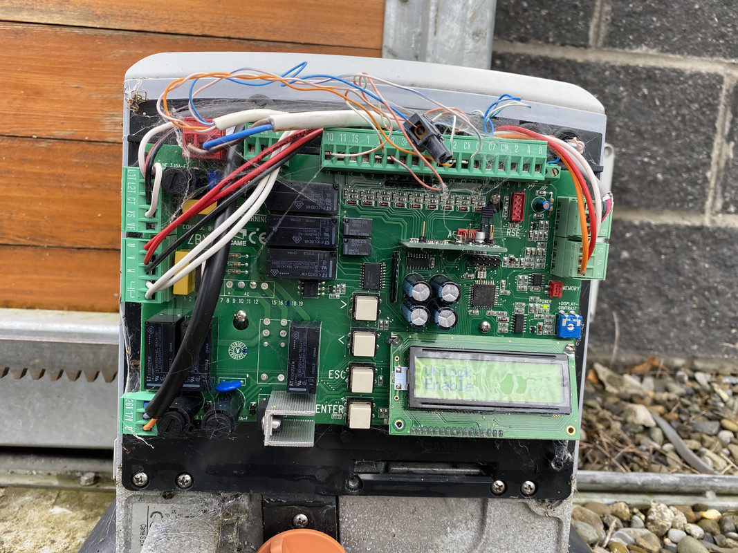
    I have a CAME gate motor (pictured below) but cant find the instructions! Picked up a RTU5024 and hoping to install it but need some assistance on wiring if anyone could help!

    IMG-8917.jpg

    is it possible to test the device with the new sim before I try install it? I know it requires a 12v power supply but not sure if its AC or DC or if as simple 12v switchmode power supply will work for testing purposes? 12v 12v 1.25A centre positive?

    Any help much appreciated. Gate was installed 3 years ago but just looking to add the GSM dialling functionality.


  • Registered Users Posts: 56 ✭✭Anj1813


    Diagram to connect rtus relay. Pin 2 and 3 to NO in rtu.
    More details later.


  • Registered Users, Registered Users 2 Posts: 4,330 ✭✭✭Homer


    Anj1813 wrote: »
    Diagram to connect rtus relay. Pin 2 and 3 to NO in rtu.
    More details later.

    Thanks for that. I have the unit setup in the house and switching a lamp on and off with the phone so just need to get it wired up to the came unit now.


  • Registered Users, Registered Users 2 Posts: 6,555 ✭✭✭kub


    Homer wrote: »
    Thanks for that. I have the unit setup in the house and switching a lamp on and off with the phone so just need to get it wired up to the came unit now.


    A NO connection across terminals 2 and 3 on the Came board should see you right


  • Registered Users Posts: 56 ✭✭Anj1813


    Homer wrote: »
    Thanks for that. I have the unit setup in the house and switching a lamp on and off with the phone so just need to get it wired up to the came unit now.

    Together with rtu, take ps and connect in gate box to 220V. Better to use independent ps than power from pcb. Your pcb has 24V. Dont use it!


  • Registered Users, Registered Users 2 Posts: 4,330 ✭✭✭Homer


    Wondering is it possible to use some of the existing wiring inside the house at the intercom location and use that for the COM/NO as there is a push button that triggers the relay to open the gate? Would be an easier install than outside at the gate location?


  • Registered Users, Registered Users 2 Posts: 6,555 ✭✭✭kub


    Homer wrote: »
    Wondering is it possible to use some of the existing wiring inside the house at the intercom location and use that for the COM/NO as there is a push button that triggers the relay to open the gate? Would be an easier install than outside at the gate location?

    Yes as it is a NO trigger you can indeed connect up with the cabling at the push button.


  • Registered Users, Registered Users 2 Posts: 4,330 ✭✭✭Homer


    kub wrote: »
    Yes as it is a NO trigger you can indeed connect up with the cabling at the push button.

    Excellent thanks. Think this will be a much easier install.


  • Advertisement
  • Registered Users, Registered Users 2 Posts: 4,330 ✭✭✭Homer


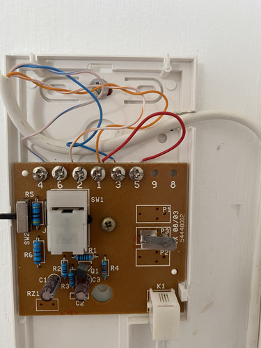
    No manual for the intercom. Any idea which two I need to use for COM/NO? Thanks for all the help!

    dY3TyF.md.jpg


  • Registered Users, Registered Users 2 Posts: 6,555 ✭✭✭kub


    Homer wrote: »
    No manual for the intercom. Any idea which two I need to use for COM/NO? Thanks for all the help!

    dY3TyF.md.jpg


    Ok when you said push button earlier i was imaging a standalone switch, what you have there looks to me like a Comelit handset.
    As only 4 of the cores on that cable are being used then i am afraid to say, that intercom only sends 12 vac to release the gate, therefore between it and the terminals at the gate controller, there has to be a relay somewhere.


    That cable in your picture, is that a Cat 5 / 6 ?
    Are the green and brown cores spare on that cable and can you trace it outwards.
    I think it mind be as easy now to perhaps use the green cores to send your NO Comm signal from the GSM unit out to the gate, but you will have to trace it.


  • Registered Users, Registered Users 2 Posts: 4,330 ✭✭✭Homer


    Will take a look at the cable. Hopefully it’s a cat5/6 with two spare cores that I can bell out and locate. Will update once I can do that. Many thanks.


  • Registered Users, Registered Users 2 Posts: 2,851 ✭✭✭tech


    It just looks like phone cable with 2 pairs?


  • Registered Users, Registered Users 2 Posts: 6,555 ✭✭✭kub


    tech wrote: »
    It just looks like phone cable with 2 pairs?

    Good point but I have a feeling the cores in phone cables are different colours


  • Registered Users, Registered Users 2 Posts: 4,330 ✭✭✭Homer


    Turns out it is indeed only 4 core phone cable so that’s that option rules out!
    On to plan B.. wired the gsm dialler up to the came unit right beside it using a long power extension cable and it’s all working so just need to house the gsm dialler elsewhere and run out a 2 core cable for the relay which should be an easy enough job! Thanks for all the advice


  • Advertisement
  • Registered Users Posts: 56 ✭✭Anj1813


    Show this board from back side.


  • Registered Users Posts: 56 ✭✭Anj1813


    The C/200 call tone is electronic, in
    addition ER/12 buzzer, figure 7, can be
    fitted into the handset.
    Function of each terminal Terminal block C 5 ground 7 call 8 audio from entry panel 9 audio to entry panel • button for • auxiliary services


  • Registered Users, Registered Users 2 Posts: 4,330 ✭✭✭Homer


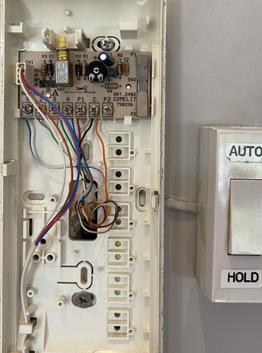
    So, have mine sorted finally yay! Got a second gsm dialler for a neighbour and they have a slightly different system from mine. Picture below of their handset where I think I may be able to hook up the gsm dialler?
    They definitely have a cat6 with all cores seem to be connected up?
    Just wondering which connections on the handset circuit board are common and NO? Promise this is the last time I’ll ask lol

    damsiN.md.jpg


  • Registered Users, Registered Users 2 Posts: 6,555 ✭✭✭kub


    Great stuff.

    P and C1, the dry contact link is already cut so hopefully that will sort you.


  • Registered Users, Registered Users 2 Posts: 433 ✭✭coxy123


    Homer wrote: »
    Thanks for that. I have the unit setup in the house and switching a lamp on and off with the phone so just need to get it wired up to the came unit now.

    Hi Homer - Is this easy enough to do with an RTU? Could you supply steps or a link to steps even. Thanks.


  • Advertisement
Advertisement