Advertisement
If you have a new account but are having problems posting or verifying your account, please email us on hello@boards.ie for help. Thanks :)
Hello all! Please ensure that you are posting a new thread or question in the appropriate forum. The Feedback forum is overwhelmed with questions that are having to be moved elsewhere. If you need help to verify your account contact hello@boards.ie

Solar PV Hints, Tips & Troubleshooting Part 2

  • 21-03-2025 12:25AM
    #1
    Moderators, Education Moderators, Home & Garden Moderators Posts: 8,302 Mod ✭✭✭✭


    As some of you may have noticed, there is a bug on Vanilla which is preventing recent posts on certain threads from showing. There is no timeline for the fix, so we're going to create new threads and link to these threads from the last visible post on the old thread.

    Previous thread:


«1

Comments

  • Registered Users, Registered Users 2 Posts: 769 ✭✭✭buzz11


    I've noticed that the load on my inverter doesn't appear to be right, see graph below where the load between 08 to 12 is virtually zero and from 22 to 04 is also virtually zero — this isn't right because the house base load is minimum 300 to 500w whereas the load recorded around is .01

    So is it a faulty meter? Its Acrel ACR10R

    TIA

    image.png


  • Registered Users, Registered Users 2 Posts: 8,936 ✭✭✭10-10-20


    Looks to me like the 'load' CT is installed on the incoming feed from the ESB, so it's reading what's coming off the grid as opposed to showing the showing the load being supplied to the house by the inverter. I think you have the correct setup as the inverter needs to see the grid load so that it can manage the export/import. That's what's implied in the doc for the meter:

    image.png

    It is a three-phase meter though and assuming you're on a single-phase system, you might be able to add a second or third CT, but whether you can do anything with that data and the inverter that you have is a question for the inverter company.


  • Moderators, Home & Garden Moderators Posts: 7,046 Mod ✭✭✭✭graememk


    Load is a calculation on solar and grid import/export - it is reading grid import correctly.

    @buzz11 do you have more than 1 inverter?


  • Registered Users, Registered Users 2 Posts: 797 ✭✭✭Exiled Rebel


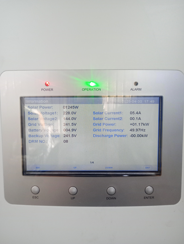
    Beautiful blue sky day but 7.79kWp array and 5kW solis inverter peaked at 2.5kW today. It seems the solar is producing roughly half what it should. I have included a photo from 20 mins ago where you can see the voltages from the two arrays (4.92kWp & 2.87kWp).

    I had a grounding issue a couple of months ago but this time there's no fault code coming up on the inverter screen.

    It should have flatlined at 5.5kW for a few hours but as I said above the highest it went to was approx 2.5kW.

    IMG_20250430_153916.jpg

    Any ideas? Solar current 2 looks to be low.


  • Registered Users, Registered Users 2 Posts: 8,936 ✭✭✭10-10-20


    I was initially going to suggest that the ambient temperature was going to impact production today, but voltage2 and current2 are way too low for that and appear to be indicating an issue as you said. What aspects are the strings on and do you have optimiser modules fitted? Is one string shaded or badly impacted by some obstruction?


  • Advertisement
  • Registered Users, Registered Users 2 Posts: 769 ✭✭✭buzz11


    Yes I have 3 inverters, one hybrid and two ordinary

    Yes the clamp is on the incoming live supply just below the board breaker


  • Registered Users, Registered Users 2 Posts: 797 ✭✭✭Exiled Rebel


    Both south facing aspect. The larger array is a ground mount and the smaller array is on a steel shed. No optimisers and no shading issue before 5pm when the shadow of an ESB pole crosses the ground array.

    I've noticed 4 or 5 large blobs of bird crap on the ground array. I'll get the garden hose and a brush out later but I suspect that's not the issue.

    UPDATE: Panels washed but still an issue with the ground array.

    17460301266058754538356725451400.jpg


  • Moderators, Home & Garden Moderators Posts: 7,046 Mod ✭✭✭✭graememk


    Yeah then that's normal, the hybrid can't calculate the load when there is other inverters


  • Registered Users, Registered Users 2 Posts: 1,025 ✭✭✭Coles


    Very interesting thread. Maybe somebody can give a bit of advice.

    I have a 3.6kwp Solis Inverter on a south facing roof operating as a single string, and I'd like to add a second identical inverter with two strings split between east and west.

    From doing the calculations the total export could never exceed 25A as the South+East would max out at 5.5kW, and then the South+West would do the same, but my question is whether or not this set-up is permitted? Is it common? Does it require a 25A Current Limiting Device? Is there such a thing?

    Thanks for informed advice.


  • Registered Users, Registered Users 2 Posts: 8,936 ✭✭✭10-10-20


    I'd go check or reseat each of the MC4 connectors, or at least start testing voltages with a volt-meter tomorrow.


  • Advertisement
  • Registered Users, Registered Users 2 Posts: 6,451 ✭✭✭championc


    PV2 voltage likely below the MPPT minimum for a string, meaning it won't generate, hence the zero current


  • Registered Users, Registered Users 2 Posts: 6,451 ✭✭✭championc


    Max permitted according to ESBN rules is a 5.5 inverter, irrespective of the ability.

    If you add an East / West, parallel the pair, ensuring both sides have exactly the same number of panels. Then optimizers are unnecessary, and they can be done ne on the one string too


  • Registered Users, Registered Users 2 Posts: 797 ✭✭✭Exiled Rebel


    I had a grounding fault in February after a few days of significant rainfall. The issue went away a few days after things dried up. I wonder is that ground earthing becoming an issue again.

    The cables from the ground array are running through a duct which appeared to be quite fragile and easily cracked if dropped. I wonder has the duct collapsed underground (it's buried about a metre down) and causing the DC cable to earth ....but the inverter isn't registering the fault so I'm a bit at a loss.


  • Moderators, Home & Garden Moderators Posts: 7,046 Mod ✭✭✭✭graememk


    Come to think of it, I've seen something similar on a failed isolator (water got in), it showed some voltage on the inverter but it wouldn't carry any power.

    Possibly a bad connection somewhere


  • Registered Users, Registered Users 2 Posts: 620 ✭✭✭idc


    following on from @graememk answer does your hybrid support monitoring of other inverters?
    I have an AlphaESS Smile5 which is hybrid inverter but has a mode confusingly called "hybrid" where the CT meter is connected to a second CT meter which monitors the output from my second string inverter (or multiple string inverters). This allows my system report the generation from the other inverter and also means grid/generation/load are all calculated correctly


  • Registered Users, Registered Users 2 Posts: 810 ✭✭✭CivilEx


    I don't know if you sorted this, but I had a similar problem with my own system last month (Fusion solar), where the system seemed to be operating at 50% capacity on a blue sky day. I switched off the AC isolators, the DC isolators and the fireman switch for 30 seconds and then turned them all on again.

    A crude solution, but it worked and it was back to normal straight away. If I see it happening more often I'll go back to my installer to check and see what is happening.


  • Registered Users, Registered Users 2 Posts: 6,451 ✭✭✭championc


    So the ground array is PV2 and is larger than PV1 ? So what should it's voltage really be ?

    The first thing that I would do is to measure the voltage of the string at the panels before the cable goes underground.

    Approximately, what should it be ?


  • Registered Users, Registered Users 2 Posts: 797 ✭✭✭Exiled Rebel


    Correct the ground array is pv2. The voltage should be circa 460v. The current reading is hovering around 200v on the inverter screen.

    I switched it off this morning and back on. Now both arrays are x#?#?£.

    17460877660083263019635137227873.jpg

    Edit.....switched it off and on again and pv1 has come back to life. Something really strange going on.

    17460879868849011740041820442383.jpg


  • Registered Users, Registered Users 2 Posts: 1,584 ✭✭✭DC999


    I had a dead fireman switch last year. I have 2 inverters and 2 fireman switches. Meant one inverter was offline. Powering off the AC and DC isolator and fireman switch didn't resolve.

    Installer replaced at no cost. I expected to pay labour but fireman unit has a 5 or 7 year warranty.


  • Registered Users, Registered Users 2 Posts: 797 ✭✭✭Exiled Rebel


    I've no fireman switch so it's not that I'm afraid. I suspect it's a bad connection or one of the DC cables in the underground conduit has been damaged.


  • Advertisement
  • Moderators, Home & Garden Moderators Posts: 7,046 Mod ✭✭✭✭graememk


  • Registered Users, Registered Users 2 Posts: 6,451 ✭✭✭championc


    Step 1. Get a DC multimeter

    Step 2: Check at first + and last - in the string

    Step 3. Check at every link point as you work back towards the inverter


  • Registered Users, Registered Users 2 Posts: 8,936 ✭✭✭10-10-20


    And bearing in mind that ~500v DC is potentially present. 👍️


  • Registered Users, Registered Users 2 Posts: 6,451 ✭✭✭championc


    But it's current that will kill you, not volts.

    You can happily touch a 12v car battery, but I would recommend it when starting the car !!!


  • Registered Users, Registered Users 2 Posts: 8,936 ✭✭✭10-10-20


    Let's be cautious here. That adage is correct to a point.

    While testing a solar system with an MPPT input rated up to 600v DC which would you prefer to receive:- a shock of 50mA at 500v DC, or 100mA at 100v DC?

    500v has the potential to do more damage to skin as it needs to overcome a lower skin resistance to pass through the body. You might have less chance of death due to the lower current of 50mA versus 100mA, but the burns will be deeper because your muscles will seize and the current will remain conducting.

    I'd be making sure that my multimeter test-leads were in good condition and that the probe ends were short and well away from my fingers. 👍️


  • Moderators, Home & Garden Moderators Posts: 7,046 Mod ✭✭✭✭graememk


    Always be on the lookout for the next thing to kill you!

    Id far rather 50v as that's below the touch voltage of skin.

    It's somewhat the reason for the 110v transformers that used to be on job sites, as its a centre tapped transformer, there's 110v between L and N but only 55v L - E. (And of course N-E now has a voltage.. of 55v)


  • Registered Users, Registered Users 2 Posts: 8,936 ✭✭✭10-10-20


  • Registered Users, Registered Users 2 Posts: 2,668 ✭✭✭bullit_dodger


    Didn't know that - that's interesting graememk.


  • Registered Users, Registered Users 2 Posts: 797 ✭✭✭Exiled Rebel


    Thanks guys for all the advice. I think it's best to contact the installer as now both arrays are down. Things were going swimmingly for most of the past 12 months. Error pv-iso-pro-002 is now appearing which is a ground fault code for the positive.

    IMG_20250504_121400.jpg
    Post edited by Exiled Rebel on


  • Advertisement
  • Registered Users, Registered Users 2 Posts: 6,451 ✭✭✭championc


    In rummaging around, you may have a bad connection to an MC4 connector on PV1, and it has now disconnected completely.

    Surely you can somewhat retrace your steps.

    Did you get anywhere at all with checking anything with PV2 ?


Advertisement