Advertisement
Help Keep Boards Alive. Support us by going ad free today. See here: https://subscriptions.boards.ie/.
If we do not hit our goal we will be forced to close the site.

Current status: https://keepboardsalive.com/

Annual subs are best for most impact. If you are still undecided on going Ad Free - you can also donate using the Paypal Donate option. All contribution helps. Thank you.
https://www.boards.ie/group/1878-subscribers-forum

Private Group for paid up members of Boards.ie. Join the club.

Wiring induction hob

  • 01-09-2025 10:11PM
    #1
    Registered Users, Registered Users 2 Posts: 8


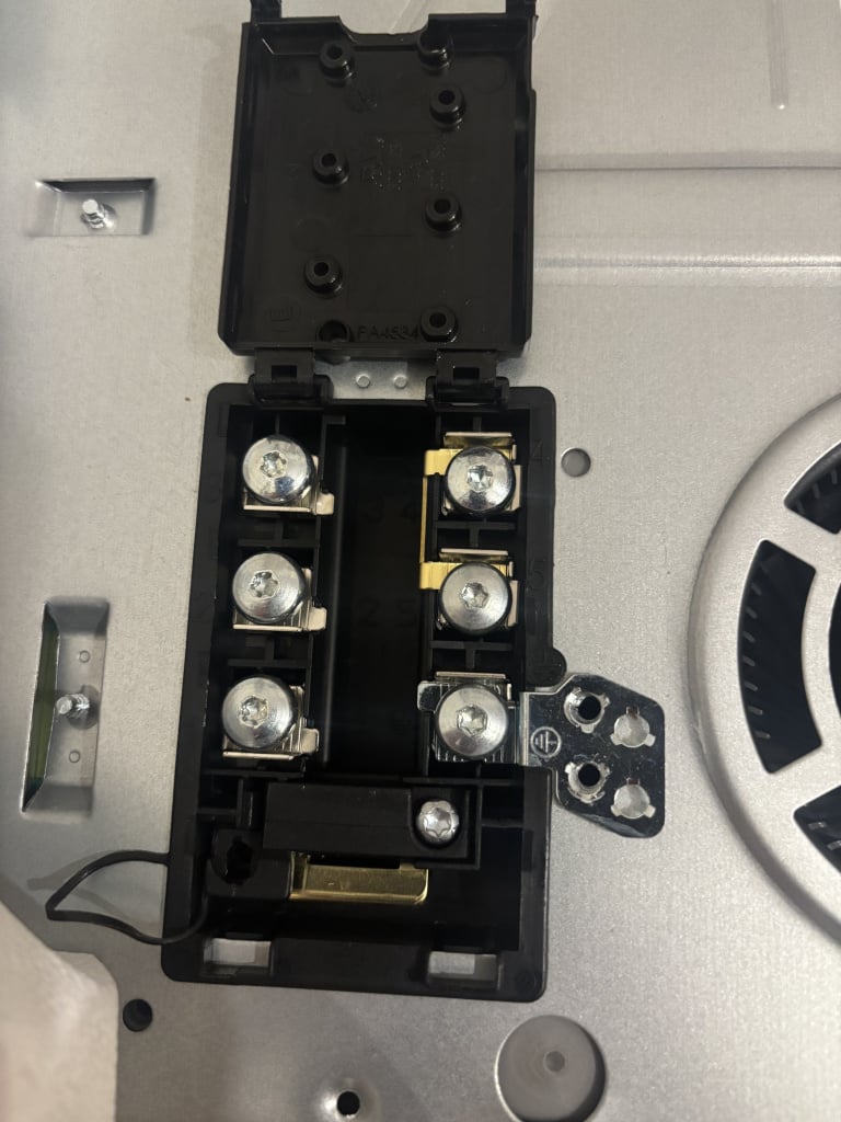
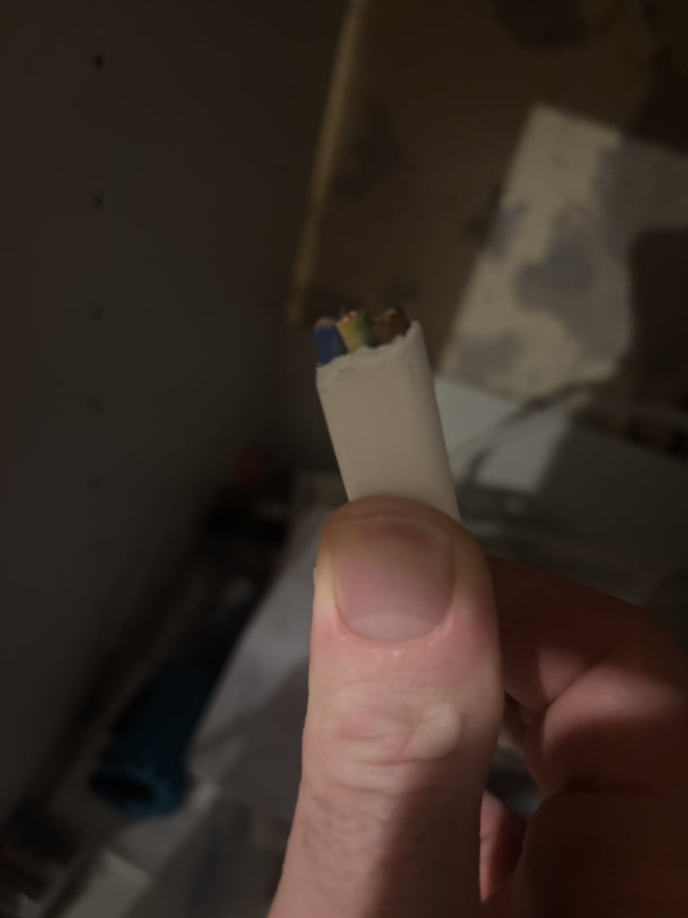
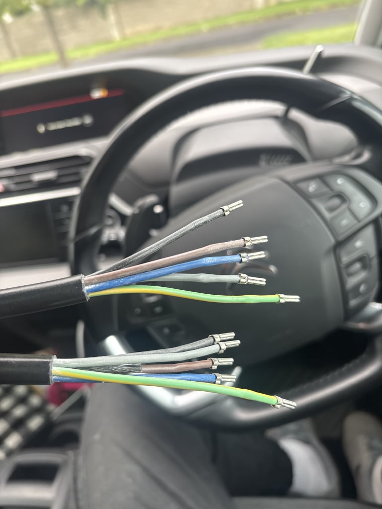
    IMG_4077.jpeg IMG_4080.jpeg IMG_E606D694-9BD3-4C10-A426-B389C53AA132.jpeg

    Can anyone tell me how to wire my induction hob using the new 6mm2 wire I bought, the wire that came with the hob isn’t long enough the picture with 5 wires, I was told that the 6mm2 wire will be perfect to run from my cooker plate outlet to the hob I’ve tried loads of electricians but all too busy any help would be great

    Tagged:


Comments

  • Registered Users, Registered Users 2 Posts: 1,550 ✭✭✭JustJoe7240


    Try more electricians. Not a job for a diyer, Using a 5 core would be bad practice.


  • Registered Users, Registered Users 2 Posts: 211 ✭✭thoneaseessi


    Probably a couple of links to be fitted best leave it anyway


  • Registered Users, Registered Users 2, Paid Member Posts: 9,449 ✭✭✭10-10-20


    Your first mistake was assuming that you need 5-core. Crack out the auld instructions there and we might have a hope.


  • Moderators, Category Moderators, Arts Moderators, Sports Moderators, Paid Member Posts: 53,901 CMod ✭✭✭✭magicbastarder


    how are you going to fit it into the car?


  • Registered Users, Registered Users 2, Paid Member Posts: 9,449 ✭✭✭10-10-20


    It might be an RV with three-phase power! Don't assume!


  • Advertisement
  • Registered Users, Registered Users 2 Posts: 917 ✭✭✭oinkely


    Is the 5 core cable picture both ends of the same cable? I assume it is and this is the cable that came with the hob? The hob instructions will tell you what the 5 cores are for and where they go in the hob connector block. Then you need to figure out which of the five cores match with the three cores in your T&E cable, and connect them in a sufficiently rated connector block. Alternatively you may be able to dispense with the 5 core cable and run the T&E directly to the hob, provided you have the correct connections at the hob with extra bridging cables. Probably best to keep looking for an electrician though.


  • Registered Users, Registered Users 2 Posts: 18,291 ✭✭✭✭AMKC
    Ms


    @Kev1293748 What part of the country do you live in? Are there instructions with this hop? It should relatively simple but before you do anything if you attempt to yourself you need to be 100 per cent sure that you have to power off to the cooker as there is no RCD or RCBO protection on cookers so no protection from getting electrocuted if you get it wrong. However there should be an isolated switch for it and it should look just like a switch marked off and on with a red neon. The best way to be sure is if you know which switch it is have it on and then go to your consumer unit and nock off the MCB marked cooker. If you are not sure or your consumer unit is not well marked then do not attempt this yourself. Also a good idea to have a reliable volt stick just to be sure that you got the right one and no power in the outlet.

    If you do however then it should be relatively simple just Earth, neutral and then live connections into the hop and the hop outlet plate connections.

    Live long and Prosper

    Peace and long life.


  • Registered Users, Registered Users 2, Paid Member Posts: 5,274 ✭✭✭blackbox


    I wired one not too long ago. It had options for 3 phase or single phase.

    The instructions were quite clear and I've had no issues, but I wouldn't have done it without the instructions.

    On single phase it automatically limits power usage - i.e it won't run all plates at max power at the same time.


  • Registered Users, Registered Users 2 Posts: 8 Kev1293748


    I didn’t assume anything that’s the cable that came with the Hob 😂


  • Registered Users, Registered Users 2 Posts: 8 Kev1293748


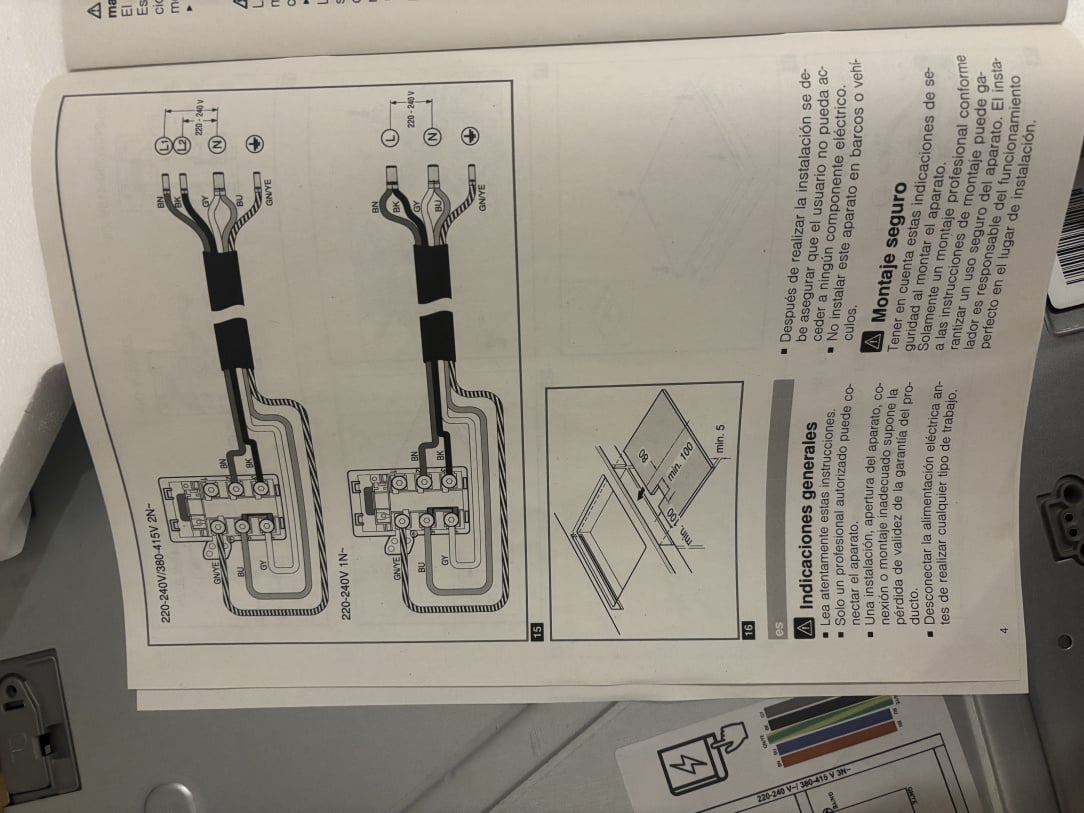
    IMG_4079.jpeg

    diagram

    Side note the wire with 5 ends is the one I got with the hob, I’m not using it as it’s too short, I’m trying to wire the 6mm2 cable what I need to know is what colour goes into them


  • Advertisement
  • Registered Users, Registered Users 2, Paid Member Posts: 9,449 ✭✭✭10-10-20


    Ok, that makes more sense. I thought that the black cable came from some supplier who crimped it for you. The correct guidance here came from @JustJoe7240 - this is not a DIY job due to the many safety issues which are common on hobs, kitchens, liquids and exposed surfaces.

    If one was to do this themselves then they need the wiring marked "220-240V 1N". 1N means one phase.

    The solid-core (white cable) isn't going to work here as it's too difficult to make a safe connection at the hob itself, that's why they supply that 5-core flexible cable. What you need to do is wire the solid core into a suitable enclosure and install a suitably rated screw-terminal block, or into an isolation switch (if not already fitted). The wiring off the solid cable then connects up to the flexible cable as per the diagram - L (brown) to BN and BK, N (blue) to GY and BU, and Green to GN/YE.

    If parts of that don't that makes sense, or/and you cannot obtain a suitably rated terminal block (and know how to use it properly) then you need to get onto an electrician.


  • Registered Users, Registered Users 2 Posts: 4,423 ✭✭✭smuggler.ie


    I am not spark.
    I have wired 4-5 of those back in the day , by instruction supplied - no one electrocuted or burn, however, i have understood in that it was taking responsibility.
    Your own call


    BN (BrowN) - L (live)
    BK (BlacK) - L (live)

    BU (BlUe) - N (neutral)
    GY (GreY) - N (neutral)

    GN/YE (GrouNd/YElow) - ground/earthing

    image.png


    Now, correct me if i am wrong, but as single phase is combining BN and BK at the isolator SW, i'd argue you can use T&E and bridge ports 2 & 3 at the hob, same way 4&5 are bridged, but for a sake of 1m cable cut…

    image.png


  • Registered Users, Registered Users 2 Posts: 4,423 ✭✭✭smuggler.ie


    I wonder, looking at the diagram, how the F*** hob would determine if this is single phase or different?
    BK and BN terminals used and i yet to see hob smart enough to determine if it comes from the same/different live feed on the isolator

    not a spark, so ready to take criticism

    image.png


  • Registered Users, Registered Users 2 Posts: 8 Kev1293748


    I asked chat GPT and this is what it said

    • That 5-core flex is universal (for single, two, or three-phase). Ireland homes = single-phase.

    • For single-phase you just bridge the lives together and the neutrals together — hence why you don’t actually need 5 wires, just L, N, and E.
    • Your 6 mm² T&E is perfectly fine to run directly from your cooker outlet to the hob.
    • Where people got twitchy is that T&E is solid-core, which isn’t as nice to terminate into that hob block (they prefer stranded/flex). That’s why some said “terminate T&E into a junction box, then flex to hob.”

    What you’ve got

    6 mm² T&E (solid core):

    • Brown = Live (L)
    • Blue = Neutral (N)
    • Yellow/Green = Earth (E)
    • Hob terminal block (6 screws, with brass links already fitted):
      • Terminals 1, 2 → Lives (linked together)
      • Terminals 4, 5 → Neutrals (linked together)
      • Terminal 3 (sometimes) → also a Live in multi-phase setups, but bridged already for single-phase
      • Terminal 6 → Earth


    How to connect
    Brown (Live) → into the Live side (usually terminals 1 & 2, which are bridged together).

    1. Blue (Neutral) → into the Neutral side (usually terminals 4 & 5, which are bridged together).
    2. Yellow/Green (Earth) → into the Earth terminal (6).

    Important notes
    Make sure the brass bridges/links are in place between 1–2 (and 2–3 if required) for Live, and 4–5 for Neutral. That ensures both sides of the hob get fed correctly from one Live and one Neutral.

    • Because your T&E is solid core, it’s a bit stiff for the hob’s connector block. Best practice is:
      • Terminate the T&E into a 60 A junction box or cooker outlet plate, then run a short piece of heat-resistant 3-core flex (6 mm² stranded) from the junction into the hob.
      • That way the hob block only sees flexible stranded cable, which grips safely.


  • Registered Users, Registered Users 2 Posts: 211 ✭✭thoneaseessi


    Seems to be 1P or 2P

    6Sq is stranded

    You should have merely connected to the existing flex . Risk damaging the terminal block or ballsing it up


Advertisement