Advertisement
If you have a new account but are having problems posting or verifying your account, please email us on hello@boards.ie for help. Thanks :)
Hello all! Please ensure that you are posting a new thread or question in the appropriate forum. The Feedback forum is overwhelmed with questions that are having to be moved elsewhere. If you need help to verify your account contact hello@boards.ie
Hi there,
There is an issue with role permissions that is being worked on at the moment.
If you are having trouble with access or permissions on regional forums please post here to get access: https://www.boards.ie/discussion/2058365403/you-do-not-have-permission-for-that#latest

Calculating a force applied at a point

  • 30-09-2022 10:50pm
    #1
    Registered Users, Registered Users 2 Posts: 8,593 ✭✭✭


    Hi,

    I'm installing a home gym and I need to figure out what the pull out rating is for the brackets on the wall to ensure I get correctly rated bolts.

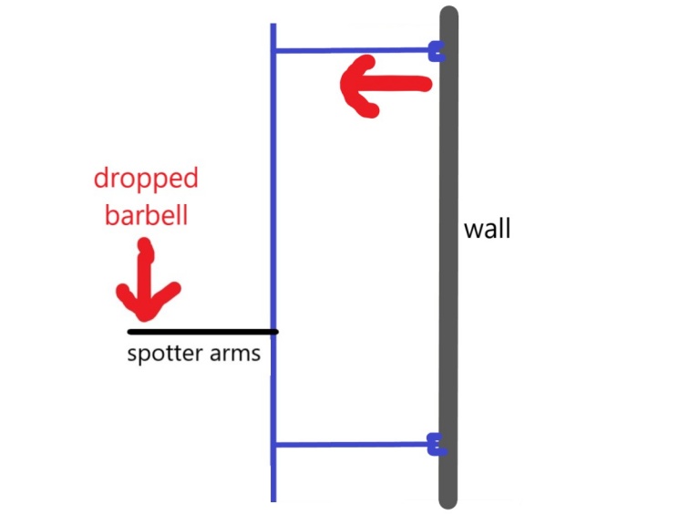
    The setup is as shown in the image below:

    The concern is related to the upper brackets. The lower ones will be fine.

    If I drop a 150kg barbell from a height of 1m it is going to produce a force on the spotter arms of 1471kN. Round this up to say 2000kN for ease of maths and some margin.

    The spotter arms are 0.6m long so working with this as the length at which the force is applied. The horizontal length from the wall to the upright is 0.5m. The distance from the spotter arms to the upper horizontal part is 1.3m. The spotter arms are 0.75m from the ground. Ignore the bottom bracket.

    What is the horizontal force applied to the upper bracket at the wall? I can't remember how to work this out.


    Thanks in advance!


Comments

  • Registered Users, Registered Users 2 Posts: 9,514 ✭✭✭TheChizler


    It's been a long time since I've thought of something like this but I think you could draw an imaginary line between the tip of the blue arrow and base of the pole and use trigonometry to convert the equal downward and upwards forces at this point into components in the plane of this line and perpendicular to this.

    Holding force not applied along this line must come from the pole at 0.75m so get the horizontal component towards the wall and use the law of the lever to convert that to the force at 2.05m.

    I think


  • Registered Users, Registered Users 2 Posts: 8,593 ✭✭✭funkey_monkey


    I hope some genius comes along as I'm not sure how to do that. Been too long.


  • Registered Users, Registered Users 2 Posts: 8,593 ✭✭✭funkey_monkey


    Is it not a moment as there is no strut supporting the horizontal?

    I had looked at example 2 here, but i couldn't get very far in relation to my query:


  • Registered Users, Registered Users 2 Posts: 1,093 ✭✭✭KAGY


    I think this is how it goes, again many years have passed! You need to work with moments, and make a load of assumptions. Let's say structure is completely rigid, and can pivot at the ground, which will give us worst case anyway

    The moment caused by the weight = moment at the wall fixing.

    Work with triangles / pythogoras to get distance from weight to ground pivot, and fixing to ground pivot

    Fd (weight) = Fd (wall)


  • Registered Users, Registered Users 2 Posts: 23,688 ✭✭✭✭mickdw


    There is a question re whether it's a fully rigid structure.

    Even though it's likely rigid, I'd look at it as pivoting at a point 0.75 from the ground as my thinking is this would produce a higher force at wall .... So rigid vertical up to 0.75 then pivot point.

    This simplifies the entire question. If you also delete the 0.5 distance back to the wall, you will simplify more although creating a slight error.

    With those simplifications, 2kN downwards at 0.6m out should produce 0.9 KN outward force at top

    With similar thinking, if you increased the fall distance to the floor and put imaginary arms at floor level, the downward force would be circa 2.5N, pivot at floor, then the outward pull at top would be circa 0.73 kN


  • Advertisement
Advertisement