Advertisement
If you have a new account but are having problems posting or verifying your account, please email us on hello@boards.ie for help. Thanks :)
Hello all! Please ensure that you are posting a new thread or question in the appropriate forum. The Feedback forum is overwhelmed with questions that are having to be moved elsewhere. If you need help to verify your account contact hello@boards.ie
Hi there,
There is an issue with role permissions that is being worked on at the moment.
If you are having trouble with access or permissions on regional forums please post here to get access: https://www.boards.ie/discussion/2058365403/you-do-not-have-permission-for-that#latest

Multiple Inverter with MyEnergi Setup - CT Config

  • 25-08-2022 2:07pm
    #1
    Moderators, Sports Moderators Posts: 19,471 Mod ✭✭✭✭


    Howdy,

    I'm hopefully coming to the end of my PV setup, I have MyEnergi products also and when it comes to CT clamps I don't have clarity in my head of their exact placement.

    I've roughed up a diagram in XL below and would appreciate some comments to see if what I am moving to is correct as I don't have all the bits up and running quite yet (just the Sofar/BMS to go along with recabling)

    CT1 is purely a monitoring CT and will not make any decision, just allows MyEnergi to track PV generation

    CT2 is similiar, just allows MyEnergi to track battery in/out

    CT3 is "functional" to allow me to move PV excess to either EDDI or Zappi (or neither if I switch both off and instead excess should flow to batteries)

    CT4 is "functional" to allow me to export limit from my second Solis PV inverter, I think all I need is one Inverter to do this as the other inverter will max at 6kW so I intent to have the second one to export at zero if it "senses" exporting above 6kW

    CT5 is purely a monitoring CT, just allows Sofar to track PV generation

    CT6 is "functional" to allow the Sofar to push excess PV into the battery or if it senses import to allow flow from the battery to load


    1. Is all above correct?
    2. Specifically, is the clamping of the tails in the correct order? This is the piece that confuses me the most
    3. Given some of the cables being clamped are very short, is there an issue with CT clamps butted up against each other? Tails in particular.
    4. Any issue with two sets of CT clamps extended on the same CAT6 cable?
    5. The potential interaction on the tails, will there be a fight?


Comments

  • Moderators, Education Moderators, Home & Garden Moderators Posts: 8,260 Mod ✭✭✭✭Jonathan


    1. See comments below.
    2. Doesn't matter. They'll see the same current flow.
    3. No.
    4. No, provided that you use a different shielded twisted pair per CT.
    5. No, per 2 above. If you are referring to the interaction between the different devices using those CTs, they'll constantly fight each other but will settle down within a few seconds.


    Comments;

    a) Zappi CT1. Move this to the LHS of the sub unit. This means that your MyEnergi generation monitoring in MyEnergi will show correct readings. In current form, generation will show as being less current Zappi consumption. You can feed both the live wires from the inverters through the same CT if required. You can also use multiple CTs and denote them as generation. MyEnergi will sum them as required.

    b) Zappi CT2. You've no electrical connection in that diagram between the ME3000 and either mini unit or CU. The Zappi CT2 will need to be on that connection, and not on the DC cabling as is indicated above. BTW, Zappi CT2 is "functional" as it is what allows you to add the battery icon in the MyEnergi app, and set priorities Eg. 1) Eddi, 2) Batteries, 3) Zappi etc. An exclusive perk of an AC coupled battery.

    c) Have you confirmed if this dual 6kW inverter/AC battery setup is acceptable to ESBN? Although you are only NC6, there are strict export limiting device requirements for NC7 mini-generation participants. I doubt CT4 qualifies because it isn't failsafe. Lots of UK DNOs require something like this to be fitted.


  • Moderators, Sports Moderators Posts: 19,471 Mod ✭✭✭✭slave1


    b) Zappi CT2. You've no electrical connection in that diagram between the ME3000 and either mini unit or CU. The Zappi CT2 will need to be on that connection, and not on the DC cabling as is indicated above. BTW, Zappi CT2 is "functional" as it is what allows you to add the battery icon in the MyEnergi app, and set priorities Eg. 1) Eddi, 2) Batteries, 3) Zappi etc. An exclusive perk of an AC coupled battery.

    I did not realise that, that is super news


  • Moderators, Sports Moderators Posts: 19,471 Mod ✭✭✭✭slave1


    UPDATED

    CT1a CT1b are purely monitoring CTs and will not make any decision, just allows MyEnergi to track PV generation

    CT2 is "functional", it allows the MyEnergi App to "see" a battery and allow it be included in "priority lane"

    CT3 is "functional" to allow me to move PV excess to either EDDI or Zappi (or neither if I switch both off and instead excess should flow to batteries)

    CT4 is "functional" to allow me to export limit from my second Solis PV inverter, I think all I need is one Inverter to do this as the other inverter will max at 6kW so I intent to have the second one to export at zero if it "senses" exporting above 6kW

    CT5 is purely a monitoring CT, just allows Sofar to track PV generation

    CT6 is "functional" to allow the Sofar to push excess PV into the battery or if it senses import to allow flow from the battery to load

    Does CT5 work for the Sofar in this config, the Sofar only has 1 CT input for PV Generation tracking


  • Moderators, Sports Moderators Posts: 19,471 Mod ✭✭✭✭slave1


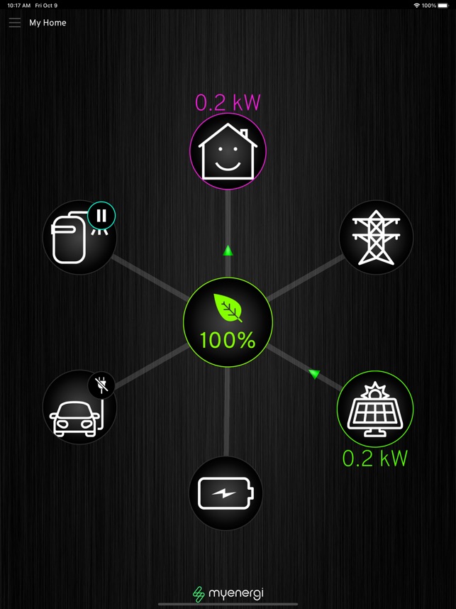
    Essentailly from a MyEnergi App perspective, it would look like this...


  • Moderators, Sports Moderators Posts: 19,471 Mod ✭✭✭✭slave1


    Wait a minute, I can’t have 2 CTs to measure PV generation as the Zappi only has 3 CT inputs, one for grid, one for PV and one for the Sofar AC coupled battery…


  • Advertisement
  • Registered Users, Registered Users 2 Posts: 16,925 ✭✭✭✭Ha Long Bay


  • Moderators, Sports Moderators Posts: 19,471 Mod ✭✭✭✭slave1


    Cheeky monkey😆

    No, my Harvi found another home after I hard wired and all it does in any case is replicate the same 3 CTs as inside the Zappi


  • Moderators, Sports Moderators Posts: 19,471 Mod ✭✭✭✭slave1


    Duh, just reread Jonathan's post

    You can feed both the live wires from the inverters through the same CT if required

    So I can combine CT1a and CT1b into the Zappi feed ..Y/N


  • Moderators, Education Moderators, Home & Garden Moderators Posts: 8,260 Mod ✭✭✭✭Jonathan


  • Registered Users, Registered Users 2 Posts: 16,925 ✭✭✭✭Ha Long Bay


    Sorry was not trying to be smart or unhelpful I thought the Harvi would allow more CT's to be added to the setup.


  • Advertisement
  • Moderators, Sports Moderators Posts: 19,471 Mod ✭✭✭✭slave1


    We’re all good man, just yanking your chain as I sold my Harvi to you so don’t have one anymore👍️


  • Moderators, Sports Moderators Posts: 19,471 Mod ✭✭✭✭slave1


    So I gave MyEnergi a shout on this as I was thinking I could tap into each Inverter output with a separate CT Clamp and then just solder them together to feed into the one CAT6 into the Zappi but they said that would not work with CT clamps, dunno why but at least I know now.

    So my course of action will be the same CT clamp around both Inverter "out" cables (live feed) to Consumer Unit, they are SWA so not going to be pretty


  • Moderators, Education Moderators, Home & Garden Moderators Posts: 8,260 Mod ✭✭✭✭Jonathan


    Might be easier to get a Harvi. @Ha Long Bay might have one for sale. 😉


  • Moderators, Sports Moderators Posts: 19,471 Mod ✭✭✭✭slave1


    LOL, I have an EDDI so I can always feed into that, but that still does not sort out that I need a PV Generation feed for the SOFAR.

    Cut into the SWA in the attic is the answer I think, just an annoying task cutting into that stuff is all


Advertisement