Advertisement
If you have a new account but are having problems posting or verifying your account, please email us on hello@boards.ie for help. Thanks :)
Hello all! Please ensure that you are posting a new thread or question in the appropriate forum. The Feedback forum is overwhelmed with questions that are having to be moved elsewhere. If you need help to verify your account contact hello@boards.ie

Solar Install; the on-going saga

Options
11113151617

Comments

  • Posts: 5,238 ✭✭✭ [Deleted User]


    Alternator pulley field testing inconclusive. Something squiffy is afoot. My numbers are lower across the range than last test and there's reduced inrush of late. As far as I can tell the belt isn't slipping because it maintains charge load under varying duty and there's no squeaking.
    I dropped to 40% SOC and the results are underwhelming and odd.
    Perhaps there's more hard starting slip on the new pulley, or my regulator is feeble or my measurement taking interval has increased.

    I can get impressive figures momentarily.

    435081.JPG

    But across most of the SOC range, the last few runs nominal current after 10mins is in the realm of 25A to 15A at ~ 45% - 70% SOC

    435082.JPG

    Adding a 10A refrigeration load reduces available charge current by 3A.

    Oddly my alternator for all the world behaves like a TriStar and they get along great. I want the alternator 2X more aggressive.

    There's potential, it has the powah, just not the gumption. This is clearly a job for two alternators. whistling.gif
    Zolotnik 2.0 coming soon!


  • Posts: 5,238 ✭✭✭ [Deleted User]


    I've "temporarily" marmaladed my new 16V 20A Constant Current Adjustable PSU in place of my tried and trusted 32V 5A. Direct swap no drama.

    435083.JPG

    I can run peak load from shore power and still maintain 110W charge to the service battery while split charging the starting battery. :cool:

    I've dialled the PSU down to 16A because it get's right toasty running at full load for 3 hours (55°C chassis temp.), circumstances will demand 12 hours full load from it, I won't be dialling it back up until after a little cooling mod.
    At 16A it holds about 40°C chassis temp.

    16A's loads..sher I usta only have 5A!

    I have the output protected with a schottky diode so the voltage drop across this means my loaded battery absorption ceiling is 15.5V
    Right now it's target is 15.1V.
    Alas.... 165W current adjustable, full duty capable, cough cough, "bolt-on" upgrade: €68 gardener.gif

    And now I have a leftover 32V PSU for the lab. :cool:

    435084.JPG

    ....with a towing rectifier from having spent 3 years service installed vertically in a MH. :o


  • Banned (with Prison Access) Posts: 63 ✭✭thedeere


    Are you mcyver?


  • Posts: 5,238 ✭✭✭ [Deleted User]


    141a7n.jpg


  • Posts: 5,238 ✭✭✭ [Deleted User]


    Readings taken at end of journey only, to allow the load to stabilise and simulate normal operating conditions. Some journeys were longer than others.

    436276.jpg

    New Baseline.

    Odd one out is probably due to foreshorted engine running. My alternator output bell curves for 5 minutes. SOC verified <5% drift.
    Readings taken no load.

    I can load up the service battery and the system will compensate at a proportional loss of charge current.
    10A load (fridge) reduces available charge current by 3A. etc.


    Alternator regulator ceiling reached.

    436277.JPG


  • Advertisement
  • Posts: 5,238 ✭✭✭ [Deleted User]


    Couldn't resist a cut and paste job on these.


    436477.JPG


    Presto USB Christmas Lights.

    436478.JPG


  • Registered Users Posts: 826 ✭✭✭autumnalcore


    Peek inside a danfoss 24v/12v motor controller.

    You've probably seen this already but if not danfoss have accommodated a fan, error led, configurable low voltage disconnect and selectable compressor speeds.
    Kompressor_101N0210.jpg


  • Posts: 5,238 ✭✭✭ [Deleted User]


    Cwaor...double thanks...Nope didn't read the manual I was planning on hacking it. :o

    Check out what I just found. It's got more features than a TriMetric svengo.gif

    1830.png

    Found a potential insulant too.


  • Registered Users Posts: 14,906 ✭✭✭✭CJhaughey


    Found a potential insulant too.

    That Armaflex is commonly used for solar thermal pipework, its good stuff, very durable.


  • Posts: 5,238 ✭✭✭ [Deleted User]


    Always time to do it right the second time..
    I've re-routed my alternator B+ to go direct to my service battery on the 35mm² link that used to serve the engine battery by proxy of the starter motor solenoid.

    I was routing:
    Alternator
    5m x 35mm² -> Starter Motor
    2m x 50mm² -> Engine Battery
    3m x 90mm² -> Service Battery Distribution
    1m x 35mm² -> Split Charge Contactor
    3m x 35mm² -> Service Battery (*Ching*)

    Now re-routed
    Alternator
    5m x 35mm² -> Split Charge Contactor
    0.5m x 35mm² -> Service Battery (*Ching*)
    2m x 35mm² -> Service Battery Distribution
    3m x 90mm² -> Engine Battery
    2m x 50mm² -> Starter Motor

    D+: Stock

    Cwaor that's a lorra contact resistance & cable impedance removed and delta voltage is gonna be a lot more interesting.

    nerd-face_1f913.png

    Probably shoulda run a ground to the gearbox too alas...nah!

    436640.JPG

    B+ landed under driver seat. Mercedes were kind enough to pre-drill two M20 holes in the floor and plugged them with a DIY cable grommit kit.
    Don't mind the filth that's a proprietary blend of battery antacid. angel.gif

    I decomissioned the Frankinductor...then recommisioned the bulk cap...it does actually reduce noise even though I was keeping it around as a battery wedge.

    436641.JPG

    New Wedge, 100A split charge contactor relocated, some soon to be redundant cables tidied..kinda..
    Albright SW80 Magnetic Latching, 100A with 800A Instantaneous. Manual Control.

    I'm still using mains colours on extra low voltage because it's all coming out soon enough and it's what I have to hand. My current anchorage isn't as well stocked as Sir Liamalot Laboratories..

    Mostly this job is just rearranging the conductors but I found myself in need of a massif crimper and a 35-8 lug....:(:rolleyes:

    436642.JPG

    It's temporary I promise! I need to chop 1m off the Cable anyway...
    tomatosplat.gif

    436643.JPG

    Find Copper Pipe - Cut - Sand - Vice - Lump Hammer - Universal Drill Bit - Flame Thrower & Solder - Grinder. Don't do it....it's barbaric!! :o

    ...works grand though...whistling.gif

    436644.JPG

    Needs a tidy when I get to back to the ranch. ...er Master Fuses?!
    - Starting circuit!....Ahem...yes, no fuses on starting circuits!...er fuses are the future!


  • Advertisement
  • Posts: 5,238 ✭✭✭ [Deleted User]


    That had the desired effect.

    I'm not sure what to write in the Zolotnik patent. "Be smarter than the Copper!" confused.png
    There's no secret sauce, no €400 boxes of electronics involed and yet it performs better.
    Anyone wanna buy a bag of boost regulators? Some blown up, some not...job lot!...the perfect stocking filler!
    New record set for peak charge current.

    436737.JPG

    It's been broken twice since. It's resting at 114.9A atm.

    Kfp.jpg
    30A @ 80% SOC and my work here is done.


    436740.JPG

    Close Enough!

    Here's the data.

    436823.jpg

    Engine battery is doing fine, it still gets positive charge current even with the autoelectrics at the far side of the starter motor.

    436739.JPG

    Engine Battery @ Full Load

    I'll keep an eye on it, if it's not 1.275 SG per cell like every other time I've tested it then I'll run the auto-electrics from the alternator B+ terminal.

    very-nice-high-five.jpg


  • Posts: 5,238 ✭✭✭ [Deleted User]


    Reworked System.
    Less is more philosophy.
    First make it work then make it simple.

    437427.jpg

    I've got a source of super-cheap 10mm closed cell polyethylene flexible foam insulation for the fridge mod.


  • Posts: 5,238 ✭✭✭ [Deleted User]


    Almost have enough stock and time to reftit the 12v distribution.

    438110.JPG

    Cable Reels and Scraps, + Major Players. Not shown are crimp terminals, crimp lugs, heat shrink and cable management.

    438112.JPG

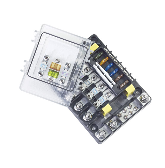
    I bought a 12-way fuse block because it was only €5 more than a 6-way.
    5mm studs are a pain in the hoop find lugs for. 6mm studs would make life a hellova lot easier.

    I like the dual positive bus they're far more versatile. I'm plumbing this one to be B1 / B2, but you could wire it Hot 12V / Switched 12V or 12-Way Common if you prefer.
    This one is complete with a naughty self resetting 20A I'm using to current limit the Smartgauge Auto Split Charge Relay but this is part of a fuse cascade and has a 25A ATO on the other side so it's an entirely acceptable application.

    438111.JPG

    My 60A Single Pole Double Throw contactor for discriminating selection between PV and 16V PSU inputs to the TriStar.
    I heart Albright Contactors they are one of the few that you can run at full rated load without melting. I'll post a photo of this beside a Durshy*e "70A" later and you'll understand what I mean.
    Albright call this a SPDT but it's contact configuration is a more versatile Normal Open, Normal Closed.

    438113.JPG

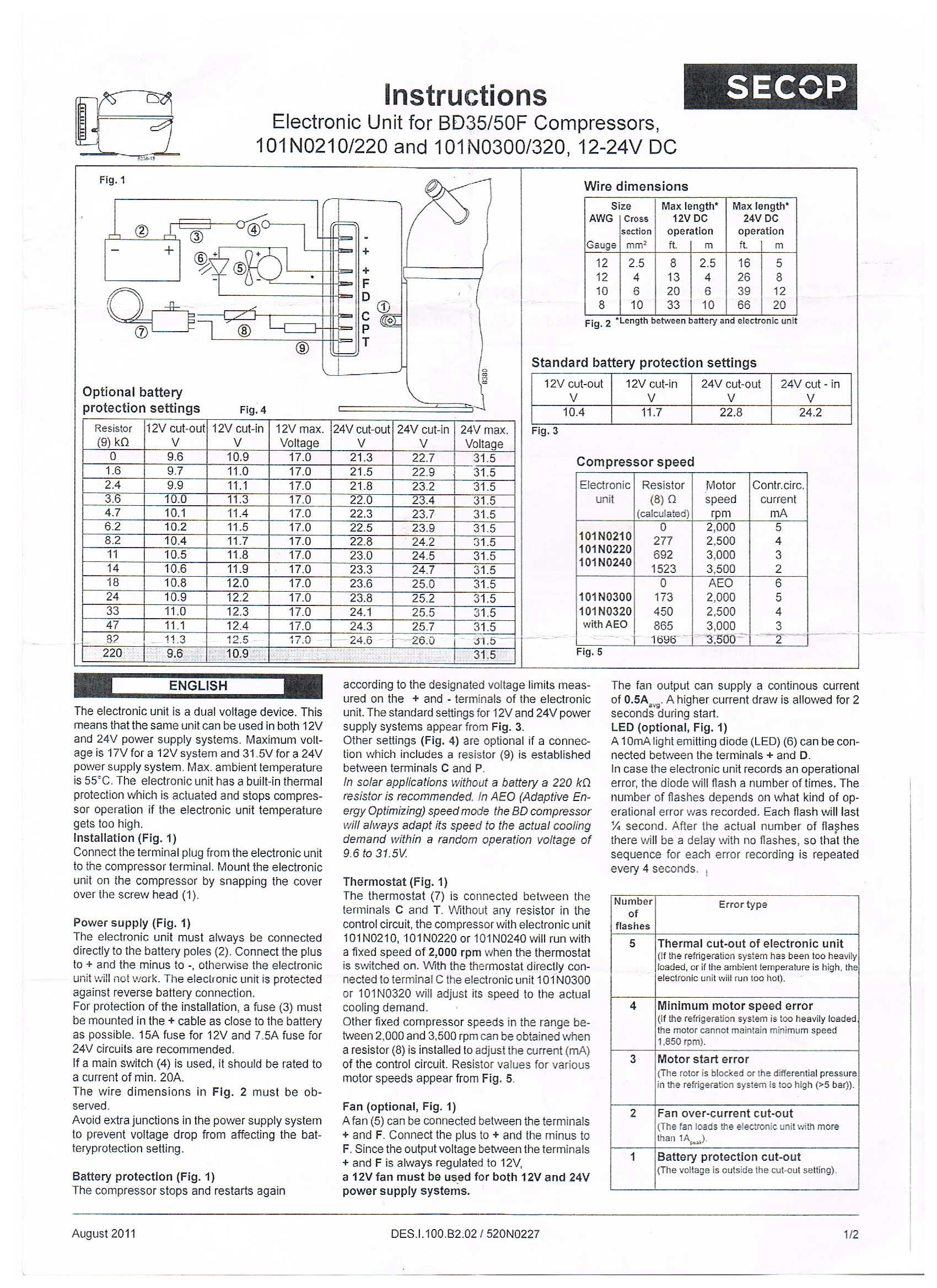
    DC MCBs and an upgraded Smartbank realay.
    The MCBs are for telecoms recently adopted by the renewables industry. The black one is polarised. Feeder to bottom.

    This is another style you can get but meh they're space hungry.
    617k%2BIhuXoL._SY355_.jpg

    I use breakers where I want the capability for no-load isolation (eg. PWM solar controllers), or the ciruit it's protecting is liable to trip due to unreliable elements like human interaction (eg. sockets).

    CCP-1-30CC-2.jpg

    438114.JPG

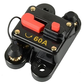
    This is a DC Rated Switch Disconnect. As you can see it bares the brand of worthiness "UL listed" from Underwriters Laboratories (the highest standard imo, head and shoulders above CE or ETL). The highlighted symbol means Switch Disconnect if it doesn't have that symbol it's only for turning on, it's not safe to turn off while operating at it's rated load.
    It's my on-load isolator for the new solar panel. Which doesn't try to weld itself when you break it thanks to preload and magnetic blow-outs.

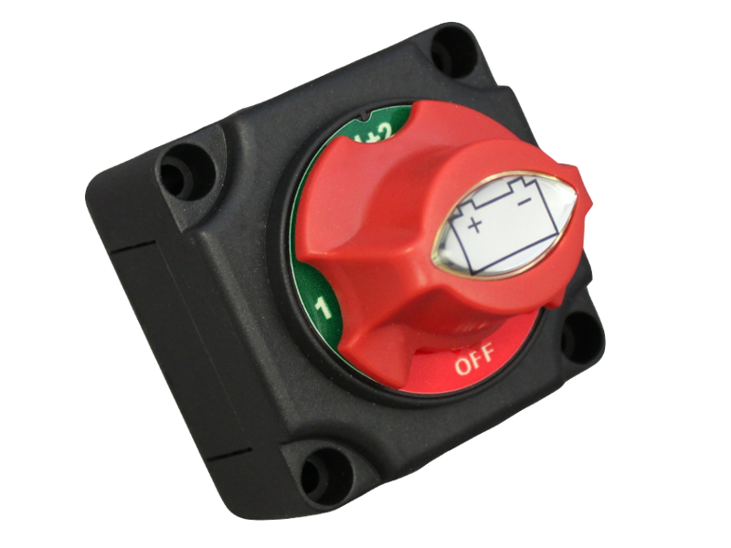
    Unlike these more ubiquitous switches that are generally kinda muck.

    Marine-battery-isolator-switch-4-positions-300A-continuous.jpg

    1 - Both - 2 - Off switch.
    Make before break. Usually nothing better than a self-assigned CE.
    Unsuitable for load breaking.
    Make before break gets pitted and worn then fails with use. Good for starting alternator fires.

    p1365_2.JPG

    These yolks are atrocious too. They like to weld closed or the contacts become heavily carbonised and high resistance. Usually not ignition protected and often fitted in the battery locker where the rearside that likes to spark is in the hydrogen containment vessel. :rolleyes:

    Garbage..if you see them delete with prejudice.

    If you're running an inverter you cannot turn it on or off no-load. Even with the output turned off the capacitor bank inrush is massif. My 2.5kVA blows chunks off my bus bars when I connect it from storage. Same goes for mid to large sized MPPT Solar controllers. So it's not ok to assume that it's not hammering your switchgear just because it's not under load.

    The difference between a DC Switch and a DC Switch-Disconnect is safety and a tenfold price difference. I can't see the economy of saving a few quid to jepardize a vehicle worth 10k's of quids...


  • Posts: 5,238 ✭✭✭ [Deleted User]


    At that rate a modern r600 mains mini fridges plus inverter losses might be better

    Your favourite spoofer engineering company brings you science! ...and of course product plugging on the matter. a_stir_it_smiley.gif


    6 o wan, half dozen o thuther.

    Assuming a 7.5W inverter quiescent....of course the datasheet for that inverter says 11.25W quiescent..&#27;onpatrol.gif


  • Registered Users Posts: 826 ✭✭✭autumnalcore


    Hadn't seen those telecoms breakers in the wild nice. The red and black boaty ones I've seen reek of shenzen chop shop fakery presumably they're badly cloned from some worthwhile original?


  • Registered Users Posts: 14,906 ✭✭✭✭CJhaughey


    Hadn't seen those telecoms breakers in the wild nice. The red and black boaty ones I've seen reek of shenzen chop shop fakery presumably they're badly cloned from some worthwhile original?

    Probably a clone of these
    http://www.vehicle-wiring-products.eu/product.php/180/battery-isolator-switch-10mm-studs


  • Registered Users Posts: 826 ✭✭✭autumnalcore


  • Posts: 5,238 ✭✭✭ [Deleted User]


    Hadn't seen those telecoms breakers in the wild nice.

    Wholesale Solar.
    If you know where they corral the captive ones drop me a link please. I know industry aren't paying those prices.

    Midnite Solar do them under their own name except they are claiming theirs can handle a higher voltage and can be used as disconnects....They don't seem to be UL listed like the rest though for some strange reason. Just ETL..the mark of expedited knock off grade...

    images?q=tbn:ANd9GcR1B6npSKje7VjAcyCuwfsl86EDCv4NAk14EbUupmSZDcGHfyPt5A
    The red and black boaty ones I've seen reek of shenzen chop shop fakery

    Yurp that's exactly what I said when I saw them too, but I'd trust Cooper Bussmann.
    Blue Sea just rebrand them and up the price. You should see what they charge for Kraus and Naimer Cams too...

    285_CB.jpg

    CJhaughey wrote: »
    Probably a clone of these

    Why would you clone that? It's muck!
    Where's the interrupt rating?
    Does it have magnetic blow-outs?
    Anti-weld contacts?
    What's the disconnect time...looks decidedly slow, like...ambiguous....:rolleyes:
    That's a switch for the control electronics of a genset. Not an electrical installation.

    Ok this is an extreme example but please let this reinforce the power of DC and the reason we need to take it a little more seriously.


    This is a DC (Limited Use) Disconnect ...look it's certified by reputable institutes!

    This is another.

    I'd strongly recommend nothing in preference to a battery isolator if you are not going to get the right type, it's just enabling the user to operate it inappropriately.

    Once one of those start to atrophy they're a liability.

    You won't find a 100A DC rated Switch Disconnect for <€100.
    I just use ex-service magnetic latching contactors with reversing switches as an affordable solution.


  • Posts: 5,238 ✭✭✭ [Deleted User]


    I was thinking about the dilema of the M5 studs. Actually it's some sortov old money 'Murican fraction thing, so are the screws and the thread pitch...anyways..ahem..M5 problem finding non-standard lugs and what a pain that would be.

    Then it dawned on me...just make it better.

    This is not a shink the hole situation. Clearly we need to embiggen the stud.

    I make busbars. I can't make them cheaper but I can make them better for the same price. I don't do it often because it's rare I actually need >300A (mostly because problems like that are better solved with higher voltage). Usually, it's a case of I need 60A, with M8 studs, decent conductivity and tinning is a plus. So I buy "250A" busbars.

    Here's a set I made earlier:

    438172.jpg

    That's what I call a 400A busbar set. :cool:

    Well errr...sher I still have the leftover M6 brass bolts with brass nuts, washers and copper spring washers. M6 like the Albright SW61 I already have a bag of lugs for...thinking-face_1f914.png

    What's on the fuse block currently? "M5" A4 stainless steel bolts....doesn't oxidise, great. Doesn't really conduct either though does it?!

    Which dya reckon is better?

    438171.JPG

    One screwdriver, lump hammer, pliers, universal drill bit, flamethrower, flux and solder later...

    438169.JPG

    I like where this is going!

    Lather, rinse, repeat.

    438204.JPG

    Ain't no kill like overkill. :D


  • Registered Users Posts: 6,522 ✭✭✭Tow


    Just don't replacement car fuses from Euro Giant, all the values are stamped out of the same diameter metal. ;-)

    When is the money (including lost growth) Michael Noonan took in the Pension Levy going to be paid back?


  • Advertisement
  • Posts: 5,238 ✭✭✭ [Deleted User]


    ....and we're back.
    5 day refit to pull out the old power centre and refit a 200A one, in preparation for a new controller (same footprint), +110W PV, a tilting mount and to shore up my new alternator potential...
    The old system was requiring streamlining and could do with upgrading.
    It was at the limits of expansion, I had nowhere to add anything except to the battery terminals.
    Most of the mains coloured cable has been removed although a lot of my 10mm² positive has a decidedly brown hue...it's red! Definitely! whistling.gif

    Here's some of the new versus old elements.

    439339.JPG

    Master Fuses. ANL versus Mega-Blade.

    I don't like those Mega-Blade holders, there's no way to install them without a janky butt crimp and 10mm² cable is a mite light for 100A anyway.

    439340.JPG

    3U Consumer Unit versus a 6U

    439341.JPG

    4-Way Blade Fuse Block versus 12-Way

    439342.jpg

    Solar / Power Supply TriStar Input Changeover Relays


  • Posts: 5,238 ✭✭✭ [Deleted User]


    A lot of a low voltage electric installers' job is metal fabrication.

    Copper is a very forgiving soft metal to work. Real basic, heat it, beat it, tap it with a drill.

    Rather than holding up the show ordering a bus bar for my circuit breakers

    391143_PIC_500-500.jpg

    I elected to make one. :rolleyes:


    I rolled out some copper pipe with a vice and lump hammer.
    The pipe is >1mm thick 6mm fingers x 5mm will give me 35mm² a breaker capability of 150A per.

    439366.JPG

    Three-ply solder sealed for bulk and corrosion protection.
    You can solder copper lam bar using a steel vice as a heat sink to differentially cool the workpiece circumnavigating the sides and wick it to centre.
    Grind to fit with a dust mask because leaded solder dust.

    Or just cut and heat shrink together is the easy option.

    439380.JPG

    Tapped M6 Brass Stud for Feeder.


    The Shunt best live on the Negative Bus.
    The only cables between the shunt battery side and the battery is the Main Battery Negative.

    439369.JPG

    You get one fold from brass then it's work hardened and brittle.
    M6 Stud filling M6 hole in middle of linking bar.


    439370.JPG

    Finally, we have the Albright SW61 Sporting a Commoning bar.
    A 2-ply, 30mm² heat shrink insulated link to common the outputs.


  • Posts: 5,238 ✭✭✭ [Deleted User]


    Two of the finest this week

    Top Tip #1
    Ctrl +Z-ing yer flat bar hole.

    Fill yer hole what's in the wrong place with a sliver of shaving. Fill with solder. Grind, measure second time. :D

    439383.JPG

    Top Tip #2:
    Don't leave your bag of heat shrink beside the space heater. :o


  • Posts: 5,238 ✭✭✭ [Deleted User]


    That's an interesting brand on the fuse block cover.

    439384.JPG

    Ah it matches. I bet the same company made that poly-blade fuse, made the cover too!

    439385.JPG


  • Posts: 5,238 ✭✭✭ [Deleted User]


    Here we have an off-brand relay from an every-expense-spared business model company, compared to an industry recognised standard.

    439387.JPG

    The SW61 is rated 80A and I can put 150A cable on it. The off brand model is rated 70A I can only fit 40A cable onto it, on a crimp terminal rated for 24A and it's half the physical size with an inflated surge rating because they know you'll never get there if you use junk like that. smiley-bangheadonwall.gif


    *(served me well running 10A the last three years).
    Upper picture is 100A, 16mm² cable beside the recommended terminal. :rolleyes:

    What's on the inside?...big contact resistance.

    Out of my charge circuit you!


  • Posts: 5,238 ✭✭✭ [Deleted User]


    I was going to reporpoise the off-brand relays for the solar actuator power controls but as they're different voltage coils I might just stick them in the gubbins pile and get a single DIN mountable relay.

    439390.JPG

    The holders come with oxidised aluminium non-insulated crimp push-on 24A terminals for installation. Not tinned copper, not tinned brass...aluminium.


    439392.JPG

    Compression gland entry grommet access drilled and fittings installed in 6U enclosure.


    439391.JPG


    Enclosure populated. Assignment has changed since. The second lighting circuit is on a fuse and that 10A DC MCB is for the solar tilting mount.


  • Posts: 5,238 ✭✭✭ [Deleted User]


    439399.JPG

    Finally someone brought a gun to a gun fight. :pac:


  • Posts: 5,238 ✭✭✭ [Deleted User]


    Day 3
    Old Electrics pulled.
    Service lighting and kitchen running from PSU (Janky Chocy-block)
    Layout mounted

    439410.JPG


    Day 4
    Main feeders and load conductors laid. Master Fuse Mounts installed.

    439416.JPG

    Buses Loaded. PE installed.

    439415.JPG

    Night 4
    SmartBank Standard wired to parallel double breaking relay terminals installed. In the weather..hrmmm...sad.gif
    Dual Snubber installed with anodes linked externally with copper plate.
    SW61 wired.

    439417.JPG

    Service powah at that point was from the PSU feeding the breaker enclosure bus bar. I kept the adapting lead I made because it means I can run the all electrics without a battery or charger in times of need. cool.png


  • Posts: 5,238 ✭✭✭ [Deleted User]


    B1 Sense. Exclusive non-load carrying sense wires to chargers and meter sense terminals. Twisted pair. Own fuse, own route direct to battery. Fused Negative Sense in case of Bus Ground failure.
    You can wind them with a drill if you are gentle.

    439421.JPG


    Day 5
    Post testing. Commissioned.

    439419.JPG

    Tidied.

    439420.JPG

    Some issues. Currently, have a moratorium on mains charging because the SW61 coil is running hot under the collar and refusing to delatch with the TriStar input live on the battery side. I have to decide where the best place for a series diode is methinks. That'll need a heat shink if it's on the charger and not just the relay coil line. The SW61 might just get that hot normally, it's a thug I can heat sink that too..sortov. I'll run it from an isolated supply and see. 12V coil at 16V...hrmmm...
    I suppose I could switch it from the shore powah instead of the PSU. Ho hum...

    Radio stopped working...nothing to do with anything...different fuse board 2 meters away. I reckon I pulled the power lead reinstalling the engine cover (to get the driver seat out). I'm taking it as a sign to run multicore to the centre console for two switched lines, B1, B2, 2 x Shunt Sense, and a B1 radio feed.

    Knocked the dirt off my shunt (didn't touch the blades or the solder). I've now got the TriMetric accurate down to -0.6W.

    I don't like the Main Distro layout. Dual ANL holders would be better

    fhd.jpg

    ..or a safety hub 150. Expensive option.

    safetyhub-150.jpg

    The chinesium holders are a flimsy, the fuses are offering mechanical support, the covers don't seat.

    439425.JPG


  • Advertisement
  • Posts: 5,238 ✭✭✭ [Deleted User]


    Somewhere between Mk-10 and Mk-11 I lost half my powah. smiley-bangheadonwall.gif

    440006.jpg

    0.25m extra 35mm², a 150A fuse and 5 extra interfaces.
    Mk-10 was a vice crimped soldered lead. Mk-11 was a screw terminal automotive battery post.

    Bring on Mk-12!

    0.5m less cable to battery.
    Double series fuse to load removed.
    Better mechanical support and cable stress relief.
    The radio is back and now on the Service Battery along with 6 other cores sent to the centre console. Whoop, no more using engine battery for service loads. ballspin.gif
    B1+ terminal filled with copper strands cauterized with an angle grinder and soldered.

    440008.JPG

    Legacy wiring removed/brought up to standard.
    Janky butt joint jump leads from Mk-3 deleted.

    440007.JPG

    SW61 is a hot potato...seems normal. I need sinks and shields.
    Still have a diode to add, to solve the delatching issue and I'm thinking a low pass filter too for audible noise reduction.

    Dual flyback diodes up and downstream TriStar fitted.

    440010.JPG

    Common anode. It's cheaper buy a dual diode and add a commoning bar in that package rather than get a common anode.


Advertisement