Advertisement
If you have a new account but are having problems posting or verifying your account, please email us on hello@boards.ie for help. Thanks :)
Hello all! Please ensure that you are posting a new thread or question in the appropriate forum. The Feedback forum is overwhelmed with questions that are having to be moved elsewhere. If you need help to verify your account contact hello@boards.ie

Media centre pc for approx €500

Options
2»

Comments

  • Registered Users Posts: 509 ✭✭✭PyeContinental


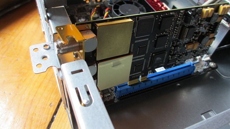
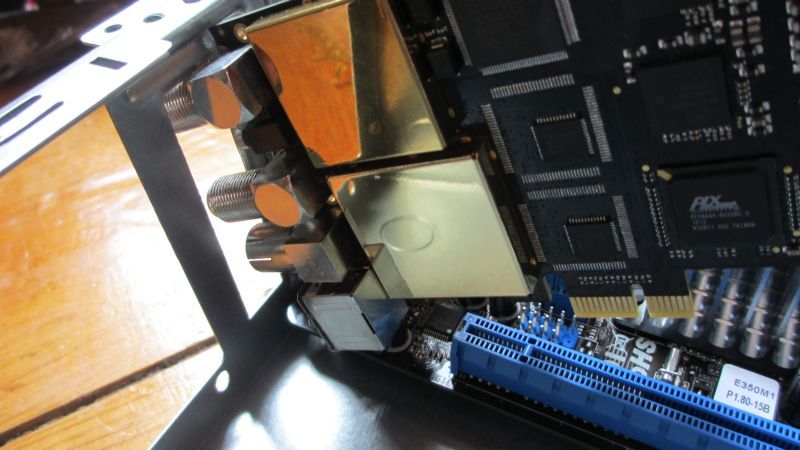
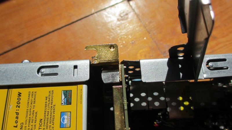
    Straight away there was a problem when going to fit the card.

    BGT3595_03_zps509a0f0a.jpg

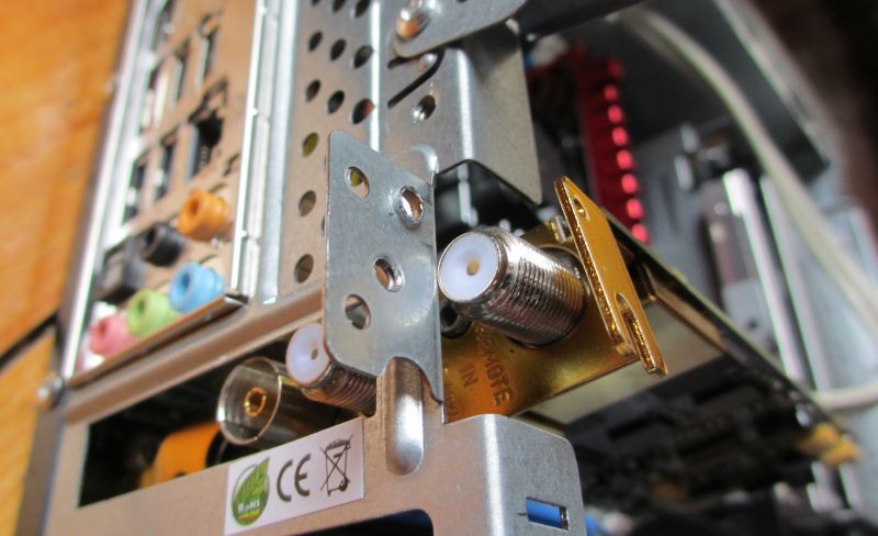
    The upper satellite cable input connector is too close to the top of the half-height bracket, so that it is impossible to fit it into the PCIe slot at the same time as get it through the expansion slot opening at the rear of the case. Basically, this is a design oversight. It would seem that they probably only tested this card in its full-height format and it didn't occur to them to test for any problems when fitting to a half-height physical format.

    BGT3595_04_zps5e93590a.jpg

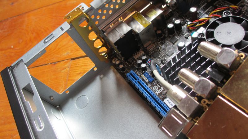
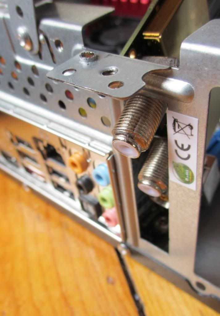
    You might think that the solution is to remove the motherboard, fit the card, and then re-fit the motherboard-with-card back into the chassis. Unfortunately, even this won't work as the satellite connector is so close to the top, it does not even have enough room to fit through the back at all.

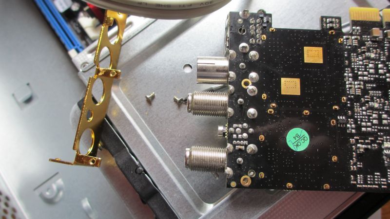
    Removing the bracket from the card and offering it up to the slot at the rear of the chassis demonstrates this:

    BGT3595_05_zps93682660.jpg

    The top satellite connector simply will not have enough room. The chassis covers about half of the aperture.

    BGT3595_06_zpse749e9b3.jpg

    I would make a good guess that the original purchaser of this card encountered the same issue and that this is why it was returned and was available to me in an "as new" condition.

    BGT3595_08_zps8f66d50c.jpg

    BGT3595_07_zps0a5595af.jpg

    Well nothing ever really goes without a hitch from start to finish, so I was prepared for this, having encountered similar issues with limited space when fitting tv-tuner and other expansion cards populated with awkward ports.

    The prospect of cutting off bits of the chassis might not be appealing to some people, but this is what needs to be done, and it's no big deal if you take your time and don't cut off any more than you need to. The metal is not very thick, and it is relatively soft. It can be done easily enough with a snips, and once you cut through one side, you can make a score in the other side and use metal-fatigue to break off the section you need to remove.

    BGT3595_11_zps527a5fe8.jpg

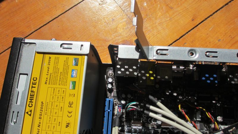
    The PSU back in the chassis restores some physical integrity, and the folding flap on this particular chassis will make sure that the card doesn't move about when it's closed over it.

    BGT3595_10_zpsc802bb7c.jpg

    I also found I needed to snip a little bit off the card's bracket to stop it fouling on the side of the chassis.

    BGT3595_13_zps14c7dac0.jpg

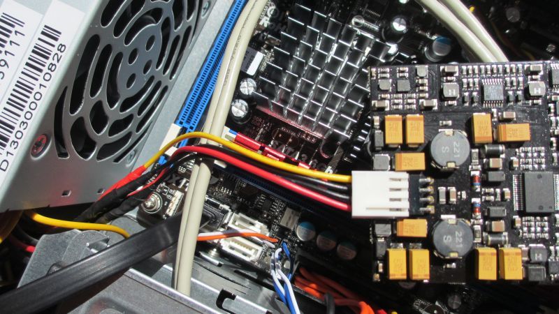
    In a similar way to many performance graphics cards, this card needs more power than can be drawn through the PCIe bus alone. It takes extra power from the type of connector usually only used in the past for 3.5" floppy disk drives. As these are now something which are very rarely used anymore, it's not surprising that a PSU designed for only a limited number of modern internal devices should no longer have one of these connectors.

    Luckily, I'm someone who keeps lots of electronic junk about the place, so I snipped an FDD power connector off an old failed PSU. I snipped off one of the older Molex type power connectors on this PSU and joined the wires.

    BGT3595_12_zpsd671e5d6.jpg

    There are Molex to FDD converters available on ebay but I think this is neater and quicker if you don't want to have to wait for another small item to arrive in the post. Of course you might later find that you need two legacy Molex power connectors for something else, but it's highly unlikely in this situation.

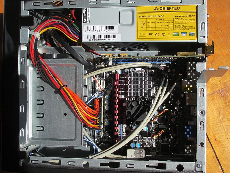
    Now here's the tv-tuner card fitted.
    BGT3595_14_zps404b8d8c.jpg

    With the expansion card flap closed over, you'd never know any part of the chassis had been cut away.
    BGT3595_15_zps3e734910.jpg

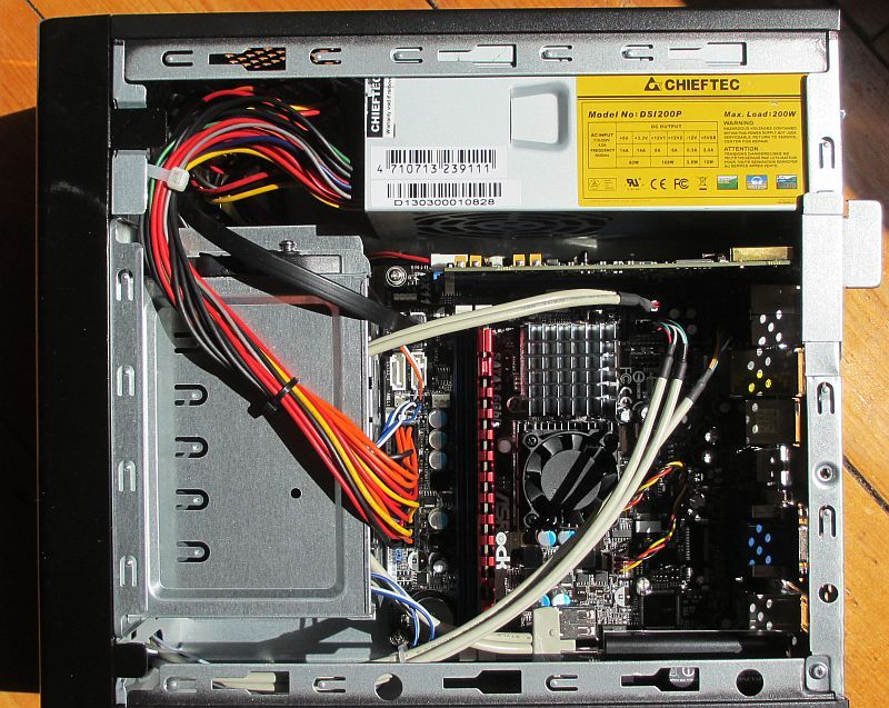
    As you can see, I have connected the other various cables such as main power connector, power button, power LED and disk LED wires, USB front ports cable to the second USB header (each header gives two USB ports) and sata cable to SSD (I'll show where the SSD goes later) and fitted the memory module. There's nothing unique to this build about any of that though, so I don't think there's any point in going into much detail there.

    Next post will be completing the hardware assembly and finishing touches ...


  • Registered Users Posts: 509 ✭✭✭PyeContinental


    I'm quite a perfectionist and I'm rarely able to leave something alone that will "just do".

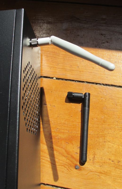
    Internal_USB05_zpsacd54850.jpg

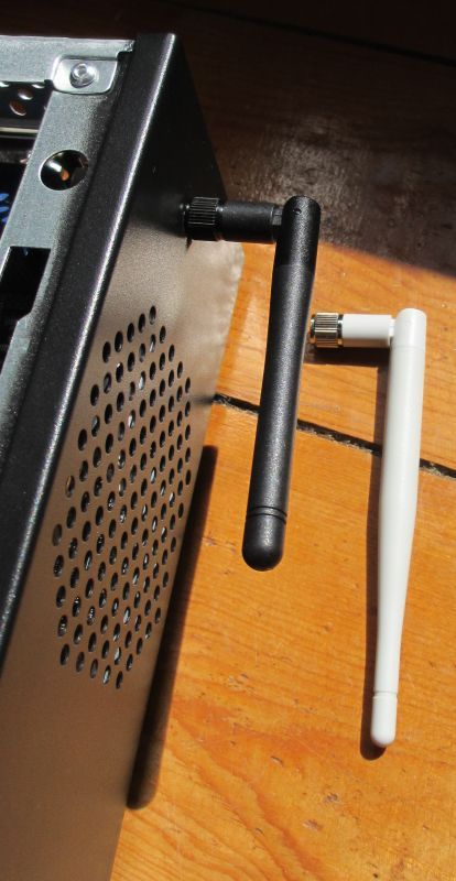
    The white wifi aerial didn't look right and I wanted it to look like it belonged there, so I swapped it for a black aerial that I had spare from an old wireless router. Again, if you don't happen to have one lying around, this is something that costs less than a fiver on Amazon.

    Internal_USB06_zps21b87fb4.jpg

    It's a small detail but I think it makes it look much better, and appearances can be important sometimes, especially for a living room device.

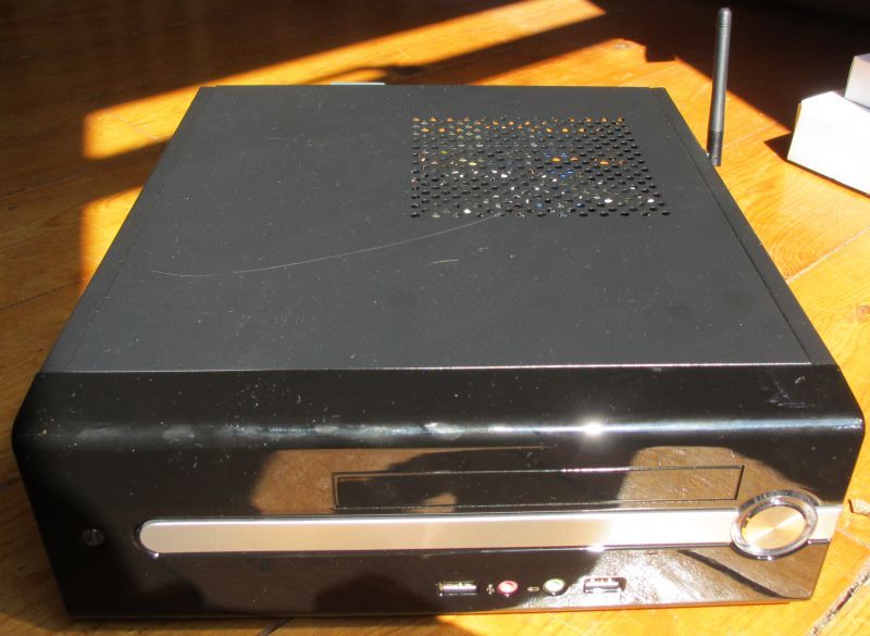
    assemble06_zpsea70e60b.jpg

    Despite my talk about appearances, I've managed to put a scratch in the top cover however. :o Hopefully it'll "polish out with a bit of T-cut", but don't make the same mistake as I did and lay it flat on a wooden floor. :pac:

    My next post will be completion of the hardware build, and a bit about the wireless keyboard.


  • Registered Users Posts: 114 ✭✭JJDoherty


    ...My next post will be completion of the hardware build, and a bit about the wireless keyboard.

    Hi PyeContinental, I have a quick question for you, if you don't mind.

    The button on the left hand side on the front panel of the Chieftec FI-01B case, what is it?

    I can't find anything anywhere, including the Chieftec website, that describes it and the photos don't give any clues away either. I think it could be a reset button or maybe a HDD activity LED!

    Thanks.


  • Registered Users Posts: 509 ✭✭✭PyeContinental


    No problem -yeah, it's a HDD activity LED, not a button.

    I've been meaning to get back to this for a while and complete the thread including OS comparison between W7 and W8 on it. I'll try to pick this up again very soon.


  • Registered Users Posts: 114 ✭✭JJDoherty


    No problem -yeah, it's a HDD activity LED, not a button...

    Ah right. then maybe I could remove the LED and use the hole for an IR receiver. The ASRock mobo I've ordered has a CIR header and a IR receiver can be got from this crowd so it's might be something worth pursuing.

    Thanks for getting back to me, I've found this thread to be really useful so far too.


  • Advertisement
  • Registered Users Posts: 509 ✭✭✭PyeContinental


    Yeah, the hole left if you took out the HDD LED could work well for that.

    This is something I intended to talk about actually, as the Asrock board used in this media centre also has a header for one of these too. I read up on it, and it seems that it was something that was never really implemented properly. The funny thing is that being a header, it implies that what's needed should be just wires to extend an IR sensor from the header to the front of your chassis. Clearly though, there's a certain amount of electronics on the board that the sensor is on, and the header, although requiring drivers, seems to be little more than a dedicated USB port.

    It's an interesting aspect though, and I would like to hear how you get on with it.


  • Registered Users Posts: 114 ✭✭JJDoherty


    Yeah, the hole left if you took out the HDD LED could work well for that...

    ...It's an interesting aspect though, and I would like to hear how you get on with it.

    That sounds good then. I've ordered all the parts for my HTPC, expect for the Inteset CIR receiver and a blu-ray slimline internal optical drive (for a later date!) so just waiting now for delivery to get started. Parts list is:

    From Hardwareversand.de
    - Chieftec FI-01B
    - Intel Celeron Dual-Core G1610
    - ASRock H61MV-ITX
    - Seagate Barracuda 7200 1TB

    From Amazon.co.uk
    - Hama MCE Remote Control
    - Kingston 4GB 1333MHz DDR3 DIMM
    - Kingston 120GB SSD
    - MS Windows 8 64 bit

    From Scan.co.uk
    - Blackgold BGT3600

    Like yourself tried to keep the cost as low as possible but getting as much bang for my buck as I can, let's see...


  • Registered Users Posts: 1 JaggedSK


    Good day. Also, I want to buy Chieftec FI-01B. What is HTPC consumption W? Source is really too noisy? A fan on the processor?


  • Registered Users Posts: 509 ✭✭✭PyeContinental


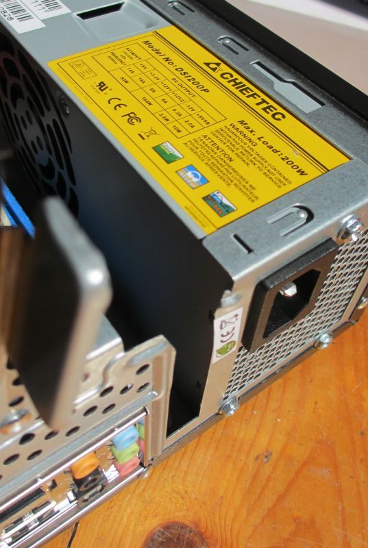
    The PSU is rated at 200 watts. I don't know what power this actual build consumes, but there have been no apparent issues with power.
    As you can see in the pics above, the CPU has a fan on it on this motherboard (other implementations of this chipset by other manufacturers are passive cooled only), but the GPU part has only a heatsink. It's a small fan and therefore makes a louder noise than a larger one spinning more slowly would. It is not completely silent, but does not make what I would call a significant amount of noise. Neither does the fan in the PSU.

    Sorry I haven't yet got around to finishing up this write-up. Hopefully I will before it becomes obsolete.


  • Registered Users Posts: 509 ✭✭✭PyeContinental


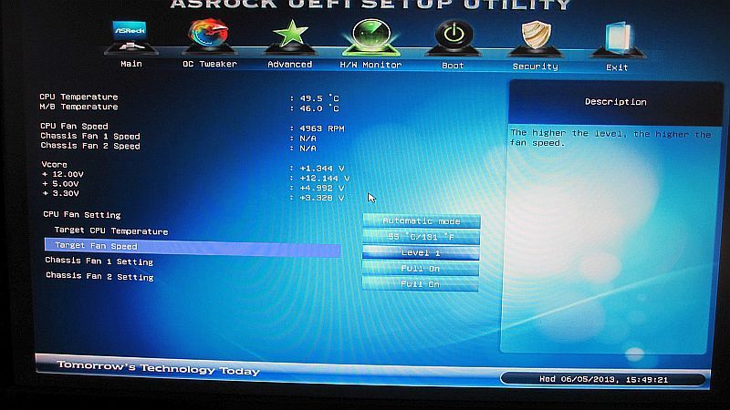
    Actually I should mention something about the CPU fan:
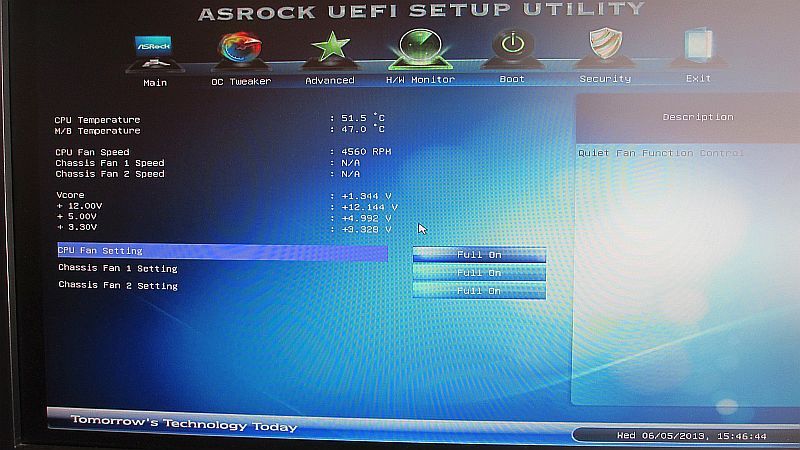
    The default settings is that it is on full speed all the time, which I thought was unusually unhelpful. At this setting it is intrusively loud.

    BIOS_fansettings01_800_zpsc73c4401.jpg

    Changing it from full to automatic, and setting it to the lowest fan speed of 1 and a target temperature of 55 degrees C (131 F) hasn't had any problems with cooling.

    BIOS_fansettings02_800_zps25f10114.jpg


  • Advertisement
  • Registered Users Posts: 893 ✭✭✭U_Fig


    Actually I should mention something about the CPU fan:
    The default settings is that it is on full speed all the time, which I thought was unusually unhelpful. At this setting it is intrusively loud.

    BIOS_fansettings01_800_zpsc73c4401.jpg

    Changing it from full to automatic, and setting it to the lowest fan speed of 1 and a target temperature of 55 degrees C (131 F) hasn't had any problems with cooling.

    BIOS_fansettings02_800_zps25f10114.jpg

    I've mine set up the same way.. I used an after market heatisink with a lot of passive cooling fins and it never reaches above 47 degree let alone 55 so the fan never comes on and keeps it silent


Advertisement