Advertisement
If you have a new account but are having problems posting or verifying your account, please email us on hello@boards.ie for help. Thanks :)
Hello all! Please ensure that you are posting a new thread or question in the appropriate forum. The Feedback forum is overwhelmed with questions that are having to be moved elsewhere. If you need help to verify your account contact hello@boards.ie
Hi there,
There is an issue with role permissions that is being worked on at the moment.
If you are having trouble with access or permissions on regional forums please post here to get access: https://www.boards.ie/discussion/2058365403/you-do-not-have-permission-for-that#latest

DIY guitar effects/stomps - Any enthusiasts?

  • 07-07-2011 5:30am
    #1
    Registered Users, Registered Users 2 Posts: 126 ✭✭


    Hey,

    I have recently picked up a few parts to build a stomp box and see how I get on. Another boardsie got me into the idea so I am wondering if there are any other boardsies out there who have tried this as abit of a hobby?

    If there are I would love to know how you got on and what you built? Maybe this thread could turn into a good source of information from what has worked for some from experience and what hasn't. Or possibly if people are interested in spending time making a particular pedal we could work on it as a group. Just throwing ideas out there anyway!

    Hope to hear from any stompers!


Comments

  • Registered Users, Registered Users 2 Posts: 1,506 ✭✭✭shizz


    Hey man. I used to be mad into this. recently I just haven't had the time but I plan to build a small solid state amp over the summer. I've made 4 pedals and one that didn't turn out to great haha. Ill try dig up the photos and post them here.

    Heres a good site for you to look through. It pretty much taught me. http://www.diystompboxes.com/smfforum/

    Some great stuff in there.

    What are you building?


  • Registered Users, Registered Users 2 Posts: 1,506 ✭✭✭shizz


    main.php?g2_view=core.DownloadItem&g2_itemId=41855&g2_serialNumber=4
    This is the first pedal I made. It's called a BSIAB 2 (Brown Sound In A Box). It is supposed to emulate that old plexi sound. Its my favourite sounding distortion real marshall sounding.

    main.php?g2_view=core.DownloadItem&g2_itemId=43598&g2_serialNumber=2
    This is Basically an 808 tube Screamer. Could be any of the tube screamers really. Its real name is Son of Screamer though. It doesn't have the Input and output buffers in it like the other tube screamers, and if I remember correctly the only difference between them is in the output buffer it's not really the exact same as any of them but IMO, and many others, there is no difference in sound. Sounds great.

    main.php?g2_view=core.DownloadItem&g2_itemId=43613&g2_serialNumber=2
    This is a digital delay pedal designed to emulate the sound of an analog one. It's designed by one of the members of that website I linked you to and the PCB was made by another member. Great quality PCB and an easy build. Lovely pedal too.

    main.php?g2_view=core.DownloadItem&g2_itemId=43622&g2_serialNumber=2
    I don't use this pedal alot. It's designed by the same member that built the PCB for this and the last pedal I think. Not to sure. Unfortunately You can here ticking in this which I have never managed to sort out. Works fine though. Im sure all I need to do is shield the input/output wires or the tempo LED.

    All the pedal box designs were designed and etched by me (loads of fun) haha And yes I am aware I spelled Tremolo wrong. oh well. :)

    Here's a link to where all these pictures are kept. I've a lot more there and a few in the process of building pictures. http://www.aronnelson.com/gallery/main.php/v/diyuser/hupla/?g2_page=1

    Keep it up man. It's well worth it.


  • Registered Users, Registered Users 2 Posts: 888 ✭✭✭quicklickpaddy


    Those cases look phenomenal! I was gonna get into this a while ago but decided I didn't have the time and I know absolutely nothing about electronics so it was a bit above me. Congrats though... They look unreal.


  • Registered Users, Registered Users 2 Posts: 1,557 ✭✭✭Knifey Spoony


    Been messing around with ideas for circuits for a year or two now, but only got around to building my first pedal last year, a tube boost pedal:

    img9681q.jpg

    Looks very "homemade" compared to shizz's stuff. Still need to get a footswitch for it, a proper case and relocate the position of the tube so I don't end up kicking it everytime I wanna switch it on and off. Been saying that I'm gonna fix it for the past year or so, put just been hard to find time to do.

    Also have a circuit for my own design for a tremolo pedal. I have it simulated and think it should kinda work, but not sure if I can produce an oscillator that will give me a low enough frequency to modulate the guitar signal. But, if I ever get around to doing it I should have three modulating options, sine wave, square wave and triangular wave. That's if I can find the time to sort out the simulation and source the right parts.


  • Registered Users, Registered Users 2 Posts: 1,506 ✭✭✭shizz


    Those cases look phenomenal! I was gonna get into this a while ago but decided I didn't have the time and I know absolutely nothing about electronics so it was a bit above me. Congrats though... They look unreal.

    Thanks man. It's not all that hard when you use the right equipment. There's a big thread on how to do it at www.diystompboxes.com. There's a downloadable PDF file from one of the members who is unreal at doing those etched designs.

    If your just getting started out I'd recommend these two sites www.beavisaudio.com and www.buildyourownclone.com.

    I already had a good understanding of electronics when I started but I bought the Beavis board from beavis audio and it really helped me get started. I would recommend it if you want to start off with building pedals that you don't want to commit to a box. Or if you want to mess around and try your own designs.

    I never used build you own clone but they supply a lot of well known pedals in kit form for you to put together.

    Check them out man. Which ever you pick it's really rewarding to build your own working pedal.


  • Advertisement
  • Registered Users, Registered Users 2 Posts: 126 ✭✭kneeelix


    Hey everyone. Glad to hear there are more people interested and wow shizz those pedals look awesome! Did they take you long to build?

    I have been trying to put a "super hard on" booster style pedal. it has very minimal components and the schematic looks quite easy to put together. I was sent a schematic by nialldabass a few months ago. Im only getting around to trying it now. great chap for sharing diy stuff! If anybody wants the schematic let me know and ill forward it on. I dont know how to upload it like Shizz's pics. Also I can give a list off parts to make it easier for people ordering and who want to give it a go.

    Beavis Audio looks great but as far as i now he has stopped making the kits for sale although I am not sure 100%. would certainly love to get the kit. there seems like alot of stuff in it for learning the basics. I have ordered most of my parts from farnell and ebay. Farnells deliverly was amazing got it the day after I ordered it. very efficient. fairly cheap if you look around.

    Knifey spooney that pedal looks great! how did you get the tube into it? looks abit odd but id say it sounds great.

    Shizz where did you source your enclosures?


  • Registered Users, Registered Users 2 Posts: 110 ✭✭nialldabass


    Hey not checked out boards for a few weeks, thanks for the compliment.
    Thats a great little starter pedal, just go for it, and those other pedals posted are amazing, alas i got side tracked with another project and have not built any more

    I ended up building this instead

    gallery8.jpg
    gallery5.jpg


  • Registered Users, Registered Users 2 Posts: 126 ✭✭kneeelix


    ^^^^^^^DROOLS^^^^^^^^
    As always you have outdone yourself. looks awesome. ever think of making your own guitar series?:p


  • Registered Users, Registered Users 2 Posts: 1,506 ✭✭✭shizz


    kneeelix wrote: »
    Hey everyone. Glad to hear there are more people interested and wow shizz those pedals look awesome! Did they take you long to build?

    I have been trying to put a "super hard on" booster style pedal. it has very minimal components and the schematic looks quite easy to put together. I was sent a schematic by nialldabass a few months ago. Im only getting around to trying it now. great chap for sharing diy stuff! If anybody wants the schematic let me know and ill forward it on. I dont know how to upload it like Shizz's pics. Also I can give a list off parts to make it easier for people ordering and who want to give it a go.

    Beavis Audio looks great but as far as i now he has stopped making the kits for sale although I am not sure 100%. would certainly love to get the kit. there seems like alot of stuff in it for learning the basics. I have ordered most of my parts from farnell and ebay. Farnells deliverly was amazing got it the day after I ordered it. very efficient. fairly cheap if you look around.

    Knifey spooney that pedal looks great! how did you get the tube into it? looks abit odd but id say it sounds great.

    Shizz where did you source your enclosures?

    Ive seen the enclosures in Maplins but this is the site I usually bought from
    www.banzaimusic.com

    It's a great site and they ship to Ireland. I can't remember if there is a delivery charge or not. If there is it wasn't much. But this is the enclosure type I used, the Eddystone B and BB. www.banzaimusic.com/Diecast-Aluminum


  • Registered Users, Registered Users 2 Posts: 1,557 ✭✭✭Knifey Spoony


    kneeelix wrote: »
    Knifey spooney that pedal looks great! how did you get the tube into it? looks abit odd but id say it sounds great.

    The tube just fits into a tube socket and then I have wires coming off of it going to various parts of the veroboard circuit. I then drilled a hole in the metal plate for the tube to fit through. It's nothing fancy, just a temperary holding for it until I get a proper container and come up with a way to house to tube in a safer way.

    Sounds pretty good alright, bit of crackle of it though, but it's a bit hard to test it fully when I don't have a switch for it. I really have to get around to ordering that soon.


  • Advertisement
  • Registered Users, Registered Users 2 Posts: 880 ✭✭✭Paolo_M


    I've not done many pedals but I have built valve amps.
    The last one was a kind of Fender Deluxe reverb clean channel with 5150 dirty.
    It's a got a valve buffered loop, choke/resistor switch, "sag" mode and solo boost.

    Here's some pics.
    CIMG0602.jpgBoard.jpg5.jpg3.jpgTop.jpgHeater.jpgCIMG0885.jpgCIMG0887.jpgCIMG0889.jpg


  • Registered Users, Registered Users 2 Posts: 1,506 ✭✭✭shizz


    Great Amp Paolo. I remember following your thread on it ages ago. Loved the sound.


  • Registered Users, Registered Users 2 Posts: 110 ✭✭nialldabass


    Now why did ya have to go and post that? You'll get Kneelix side tracked from his pedal builds, cause I know he's been looking at kit amps aswell:D

    Looks fantastic, defo on my wish list of things to try my hand at, but your work is super neat, I see you have an amp cradle, homebuilt? and did you make and tolex the cabinet? Super job if you did.


  • Registered Users, Registered Users 2 Posts: 880 ✭✭✭Paolo_M


    shizz wrote: »
    Great Amp Paolo. I remember following your thread on it ages ago. Loved the sound.

    cheers, i'm only now getting around to making proper clips
    here's a go i made today of the night rider theme...
    http://www.netmusicians.org/files/22-knight%20rider.mp3
    i'm not too sure about the stabby guitar part on second thoughts


  • Closed Accounts Posts: 23,718 ✭✭✭✭JonathanAnon


    shizz wrote: »
    main.php?g2_view=core.DownloadItem&g2_itemId=43598&g2_serialNumber=2This is Basically an 808 tube Screamer.

    wow, that's incredible.. where do you get the schema for the pedals?
    I built one as a college project, but it looked a bit more like Knifey Spooney's .. :( .. (no offence)..


  • Registered Users, Registered Users 2 Posts: 1,506 ✭✭✭shizz


    wow, that's incredible.. where do you get the schema for the pedals?
    I built one as a college project, but it looked a bit more like Knifey Spooney's .. :( .. (no offence)..

    Thanks man. Well I did up the layout of that pedal myself on stripboard, but I got the schematic from numerous places. It can be seen at the bottom of this article (which is a good read) www.geofex.com/article_folders/tstech/tsxtech.htm

    It's also found clearer here at beavisaudio.www.beavisaudio.com/bboard/projects/

    It's under the name boutique screamer. Although there is one thing wrong with there schematic which I have emailed them a few times about. If you cross reference the two (besides maybe a few different values) they left out a 47uF Capacitor going from the potential divider of two 100k resistors. (in the geofex article it is a potential divider of 10k resistors, this doesn't matter). Anyway the absence of this capacitor greatly reduces the gain so I highly recommend it is in there.

    There's a wealth of info out there and I know I've pimped this site a lot but it's like the central hub for all of these topics so I highly recommend venturing there.


  • Registered Users, Registered Users 2 Posts: 126 ✭✭kneeelix


    Nice Knight rider theme there paolo! And very nice amp. did you get that from amp maker? The point to point construction looks great and surprisingly sparse of parts? what is the wattage on that by the way?

    Niall you are right. I am so very tempted right now. I have been perusing the websernet for amp kits. Teasing myself.

    My lovely 3PDT swicth arrived today so I cant wait to rig it up and start testing the circuit. Last Time I tested it all I got was buzzing and I the input diodes got fried so I am not sure what Im doing wrong there. Any ideas? Luckily I bought a tonne of them on special offer at 0.004 Euro each!So I have plenty of spares.

    Cheers for that shizz I am going to pick up some enclosures from that site. they are much cheaper than the ones I saw in Maplin. Roughly the same size for about 15 euro.


  • Registered Users, Registered Users 2 Posts: 1,506 ✭✭✭shizz


    kneeelix wrote: »
    Nice Knight rider theme there paolo! And very nice amp. did you get that from amp maker? The point to point construction looks great and surprisingly sparse of parts? what is the wattage on that by the way?

    Niall you are right. I am so very tempted right now. I have been perusing the websernet for amp kits. Teasing myself.

    My lovely 3PDT swicth arrived today so I cant wait to rig it up and start testing the circuit. Last Time I tested it all I got was buzzing and I the input diodes got fried so I am not sure what Im doing wrong there. Any ideas? Luckily I bought a tonne of them on special offer at 0.004 Euro each!So I have plenty of spares.

    Cheers for that shizz I am going to pick up some enclosures from that site. they are much cheaper than the ones I saw in Maplin. Roughly the same size for about 15 euro.

    Input diodes? Does the guitar signal go through them? Can i see the schematic and maybe a shot of your wiring?


  • Registered Users, Registered Users 2 Posts: 126 ✭✭kneeelix


    shizz wrote: »
    Input diodes? Does the guitar signal go through them? Can i see the schematic and maybe a shot of your wiring?

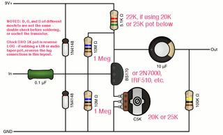
    Sorry my terminology isn't clear her. I mean the Diodes at the input end of things. I forgot I didn't post the schematic originally. I keep smelling burnign and they heat up pretty hot pretty fast. I have the 5.1kohm resistor in series with a 5k pot. I will try get a pic of my breadboard. Another possible problem is I didn't have a 0.1uf cap so I salvaged one from a circuit board i had in my bits drawer (c'mon we all have one:p).
    It is possible I have wired up the inputs and out put wrong too as I wasn't too sure how to but I gave it a bash. Its a simple enough Schematic which has me wondering what Im doing wrong.

    sho_mac_2.jpg

    I have a stereo input and a mon output. Is there a standard way to wire each of the probes and the ring on the inputs/outputs? I thought it might be something to do with not having a proper switch so I ordered some. I will get a picture and post it soon. but for the minute here is the schematic. Thanks Shizz


  • Registered Users, Registered Users 2 Posts: 1,506 ✭✭✭shizz


    kneeelix wrote: »
    Sorry my terminology isn't clear her. I mean the Diodes at the input end of things. I forgot I didn't post the schematic originally. I keep smelling burnign and they heat up pretty hot pretty fast. I have the 5.1kohm resistor in series with a 5k pot. I will try get a pic of my breadboard. Another possible problem is I didn't have a 0.1uf cap so I salvaged one from a circuit board i had in my bits drawer (c'mon we all have one:p).
    It is possible I have wired up the inputs and out put wrong too as I wasn't too sure how to but I gave it a bash. Its a simple enough Schematic which has me wondering what Im doing wrong.

    sho_mac_2.jpg

    I have a stereo input and a mon output. Is there a standard way to wire each of the probes and the ring on the inputs/outputs? I thought it might be something to do with not having a proper switch so I ordered some. I will get a picture and post it soon. but for the minute here is the schematic. Thanks Shizz

    I would check the orientation of the diodes alright. Its possible you are short circuiting the 9v to ground and causing a high amount of amps to go through the two diodes. Did you damage the transistor?

    And yeah there generally is a standard way to wire them. Specially if you want the battery disconnected when you unplug the guitar lead on the input. That's why a stereo plug is used on the input jack, for the extra pins. Generally this is the set up, StompboxWiring96.gif

    Hope this helps. Are any of the jacks attached to a metal enclosure? If the metal enclosure isn't properly grounded this can cause buzzing.


  • Advertisement
  • Registered Users, Registered Users 2 Posts: 126 ✭✭kneeelix


    Oh very nice! thats a really helpful diagram. I dont have a dc power jack input but it does look like a nice addition.

    I will double check the diodes and check the amps through it using some sacrificial diodes:D and the multimeter. As far as I know the transistor is grand. It hasnt been exposed to heta or static. I will change it out though just to be sure. My wiring currently looks like a rats nest so I will try clean it up and make it abit easier to spot mistakes. An extra set of eyes would be great incase I am doing something horrendous. The jacks also are not attached to any enclosure. How do you ground them normally? just attach them to the metal casing?

    Also this is a real noob question but does it matter what the orientation of the switch is? for instance in that schematic if you turned the switch 90 degrees to the right so the top left lug which is shown as a horizontal line (metal attachments for the wires - Incase there are any other noobs reading;)) looked vertical but is now in the top right position and all the wires were the same would it work the same? I only ask because I have seen numbered references for the lugs and also some stuff about the poles (3PDT switch has 3 poles but what way do they go?)


  • Registered Users, Registered Users 2 Posts: 1,557 ✭✭✭Knifey Spoony


    kneeelix wrote: »
    Also this is a real noob question but does it matter what the orientation of the switch is? for instance in that schematic if you turned the switch 90 degrees to the right so the top left lug which is shown as a horizontal line (metal attachments for the wires - Incase there are any other noobs reading;)) looked vertical but is now in the top right position and all the wires were the same would it work the same? I only ask because I have seen numbered references for the lugs and also some stuff about the poles (3PDT switch has 3 poles but what way do they go?)

    I hope that I can explain this without really confusing you.

    The 3PDT switch has three poles (like you said) which switch between two different positions. So, in shizz's diagram above, the middle row of pins would be the base of the pins. The poles can then be switched from the top row to the bottom row of pins (which could be the input or output of the switch, depending on which way you wire it), hence double throw (DT).

    So, it would make a difference which way it is wired because you would no longer be wiring to what you think the input or output of the switch is. So, turning it 90 degrees the top row (from left to right) would be an output pin, pole base and input pin, not what you would want at all. I hope that is clear.

    There should be some sort of marking on the switch to let you know which side is which.


  • Registered Users, Registered Users 2 Posts: 126 ✭✭kneeelix


    Thanks Knifey Spooney, That explains things pretty well. So am I correct in saying that by 3 Pole it has two "on" positions and one "off" position? if this is the case, how come we need two on positions? would it not be better to use a 2PDT switch instead?

    Shizz your diagram really helped me with trouble shooting and wiring. I realised that my circuit appears to be right but the polarity of the battery was reversed so the +9V was where ground should be and thats why the diodes where getting fried! I now have sound passing through the pedal when its not on (which Im guessing is correct?) but I need a new battery before I can test it when its on...:D I will post pics of the circuit if its still not working after the new battery. I was thinking I may turn it into a beavis inspired board to aid with future builds to save time!


  • Registered Users, Registered Users 2 Posts: 1,557 ✭✭✭Knifey Spoony


    kneeelix wrote: »
    Thanks Knifey Spooney, That explains things pretty well. So am I correct in saying that by 3 Pole it has two "on" positions and one "off" position? if this is the case, how come we need two on positions? would it not be better to use a 2PDT switch instead?

    Your not really correct in saying that. The switch only has two positions which it can switch between, the top row and the bottom row. Hence the name Three Pole Double Throw 3PDT. So, really only one "on" and "off" position.

    Say if you just take one column of pins on the switch, say the left hand column, then the middle pin would be the connection to the base of the switch. Now, the signal that is applied to the middle pin can then be sent to either the top or bottom pin. Changing which pin the signal is sent to from the middle pin is what happens when you push the switch.

    Looking at just one column of pins is the same as having a single pole double throw (SPDT) switch. So, if you place three of these SPDT switches side by side you get your 3PDT switch.

    You could use a 2PDT switch instead, but I think that you might not then be able to use an indicator LED and I think that 3PDT switches can give you true by-pass, but I am not 100% sure about this.

    Hope that this has cleared things up.


  • Registered Users, Registered Users 2 Posts: 276 ✭✭zafo


    Your not really correct in saying that. The switch only has two positions which it can switch between, the top row and the bottom row. Hence the name Three Pole Double Throw 3PDT. So, really only one "on" and "off" position.

    Say if you just take one column of pins on the switch, say the left hand column, then the middle pin would be the connection to the base of the switch. Now, the signal that is applied to the middle pin can then be sent to either the top or bottom pin. Changing which pin the signal is sent to from the middle pin is what happens when you push the switch.

    Looking at just one column of pins is the same as having a single pole double throw (SPDT) switch. So, if you place three of these SPDT switches side by side you get your 3PDT switch.

    You could use a 2PDT switch instead, but I think that you might not then be able to use an indicator LED and I think that 3PDT switches can give you true by-pass, but I am not 100% sure about this.

    Hope that this has cleared things up.

    You're right about the led with the 3dpt for using an led, general consensus is using the middle row for the indicator led and the outer ones for input and outputs. However if you skip the led a 2dpt will also give you true bypass.

    Here's a few nice layouts for the super hard on layout. I find the vero to be the easiest to work with.

    main.php?g2_view=core.DownloadItem&g2_itemId=23465&g2_serialNumber=2

    and here's what I consider the best resource for explaining all the off board wiring, ie switch, jacks, power, led etc, although there's nothing wrong with the one shizz posted above.

    http://gaussmarkov.net/wordpress/thoughts/wiring-up-a-1590b/

    I'd also recommend madbeanpedals.com for printed circuit boards and using a socket for the transistor to make sure you don't fry it while soldering.

    I've made a **** tonne of pedals for myself and friends at this stage, it's highly addictive! Enjoy!

    Also freestomboxes.org is a great website for explanations and layouts.


  • Registered Users, Registered Users 2 Posts: 1,506 ✭✭✭shizz


    Yes Guassmarkov's site is very helpful. It can be addictive alright :) GET MAKING


  • Registered Users, Registered Users 2 Posts: 126 ✭✭kneeelix


    This is great! thanks guys. I have been away from boards for too long and have not progressed too much further all though I have made a makeshift Beevis board to help speed up the DIY process. biggrin.gif

    Thanks alot knifey thats cleared up my confusion. So when "off" the circuit board is bypassed and the input routes to the output and when its "on" the led lights up and the input routes into the input of the circuit board and outputs from the circuit board. seems simple now.

    Very Nice zafo. where did you get that layout? its nice to have all the possibilities summarised so concisely. Also great tip on the IC sockets to prevent component damage. I will have to put a few of them on my next order. I really like that gaussmarkov site. He explains things very clearly.
    I did happen to find a nice piece of veroboard/stripboard so I might have a go at that once I get the circuit working properly. (this has to be the slowest SHO ever built tongue.gif)

    Your right this is quite addictive. I dont have the SHO working yet and I am considering a red llama. It sounds pretty good and relatively simple compared to some stomps. at least for the beginner.

    I have actually been meaning to ask what pots you guys use in general. I dont want to buy pots that are way over specified for the job. I have read to buy audio pots for volume controls and linear for gains and other knobs. There is alot to choose from and quite abit of variation prices. I dont want to fry the pots so I have been wondering about the power rating and what would be commonly used etc. Most of the parts lists seem to just say a 500k pot / 5k pot etc surely the voltage rating or current rating are important as well as the tolerances?


  • Registered Users, Registered Users 2 Posts: 1,557 ✭✭✭Knifey Spoony


    kneeelix wrote: »
    I have actually been meaning to ask what pots you guys use in general. I dont want to buy pots that are way over specified for the job. I have read to buy audio pots for volume controls and linear for gains and other knobs. There is alot to choose from and quite abit of variation prices. I dont want to fry the pots so I have been wondering about the power rating and what would be commonly used etc. Most of the parts lists seem to just say a 500k pot / 5k pot etc surely the voltage rating or current rating are important as well as the tolerances?

    The actual type of pot that you use shouldn't really matter if you are just powering it from a battery since the amount of current that you would draw would be no where near enough to fry the pots. Actually, if a power rating is given, then it is probably for high current applications and you really won't need them. As for tolerances, they shouldn't matter unless you are looking for a very specific range, but it normally shouldn't matter and you probably won't be able to tell the difference from a lower tolerance pot and a higher tolerance one.

    Generally, audio pots are used for volume alright, and linear for tone etc, but there is no real difference in them, only that the audio pots have a logarithmic increase in their value as oppose to a linear increase.

    The actual values that you use depends on the application though and really what you want it to do.

    Really putting my degree to good use here :P.


  • Registered Users, Registered Users 2 Posts: 276 ✭✭zafo


    I pretty much always use Alpha 16mm pots. http://www.banzaimusic.com/Mono-Full-Shaft/

    I'm not 100% sure where I got that sho layout but google is handy, just type in "sho vero layout" and you'll get a nice choice, same goes for other pedals. Fuzz face variants are also a fairly easy beginners project.

    http://www.google.ie/search?q=fuzz+face+vero+layout&oe=utf-8&rls=org.mozilla:en-GB:official&client=firefox-a&um=1&ie=UTF-8&tbm=isch&source=og&sa=N&hl=en&tab=wi&biw=1280&bih=660

    These two guys generally do great layouts.

    http://static3.nagi.ee/i/p/609/11/15227811ed62e0_o.jpg

    http://www.aronnelson.com/gallery/main.php/v/DRAGONFLY-LAYOUTS_0/album17/album06/

    They can be found between diystompboxes.com and freestompboxes.org

    I prefer the later myself.


  • Advertisement
  • Registered Users, Registered Users 2 Posts: 126 ✭✭kneeelix


    Haha cheers knifey. The power ratings I saw on farnell and radionics are just there for completeness i think alot of the smaller pots are rated in the mW region so I was unsure and i didnt want to spend a fortune as some of the pots listed are like 22euro a pop.

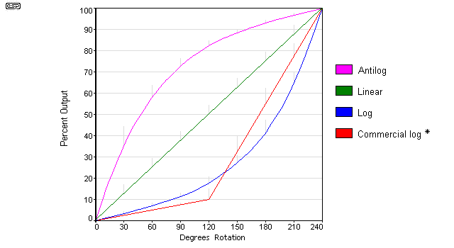
    What do you use reverse log pots for? I know the reason for log pots is to try and match the way the ear percieves an increase in sound. we think its linear but its not. I can see the difference clearly from the graph but is there a physical or noticeable difference between them or when to use them or does it really matter? pots-f4.gif

    Thanks zafo. I decided to buy a decent supply of parts off banzai today. their pot prices are excellent compared to anywere else ive seen especially maplin and peats. I have a feeling the reason mine hasnt been working is that some of the parts were salvaged from old circuit boards from radios and computers etc so I got some new parts and will go from scratch and eliminate all of the problems step by step hopefully that helps.

    Ive heard aron nelson mentioned all over the place. he seems to be some sort of stomp diy guru!

    Also just on the enclosure side of things radionics have a great supply of hammond enclosures which i think work out a little bit cheaper than banzai when you factor in shipping etc although all prices are ex VAT. (sneaky buggers :rolleyes:). I bought a few so hopefully they will arrive monday at the latest. cant wait to start building. Pics to come soon!!


  • Registered Users, Registered Users 2 Posts: 1,557 ✭✭✭Knifey Spoony


    kneeelix wrote: »
    Haha cheers knifey. The power ratings I saw on farnell and radionics are just there for completeness i think alot of the smaller pots are rated in the mW region so I was unsure and i didnt want to spend a fortune as some of the pots listed are like 22euro a pop.

    What do you use reverse log pots for? I know the reason for log pots is to try and match the way the ear percieves an increase in sound. we think its linear but its not. I can see the difference clearly from the graph but is there a physical or noticeable difference between them or when to use them or does it really matter?

    I think that graph is wrong, it may have mixed up the antilog and log graphs or could just be the varibles that it's plotted with that I can't get my head around. Anyway, this is what I know as a log graph and this is an antilog or reverse log or exponential graph.

    No idea what you would use a reverse log pot for. Just looking at the graphs, one would give you more sensitivity to small changes for a certain range of the pot. Like, the log graph would have a relatively large change in its resistance for small changes of rotation of the pot near the start of its range (low resistance region) and a relatively small change for changes in rotation near the end of it's range (high resistance region).

    But, at the end of the day it won't really matter which you would use, I would imagine, as they both you do the same thing, just a different way of doing it and I would say that you might not notice the difference in them if you are just using them as standard volume controls and not constantly varying the volume for some effect, like a volume pedal.

    ***EDIT: forget the above about the graph being wrong and use the graphs that I provided as a guide to the differences between what log and exponential pots can give for resistance.


  • Registered Users, Registered Users 2 Posts: 1,506 ✭✭✭shizz


    I think that graph is wrong, it may have mixed up the antilog and log graphs or could just be the varibles that it's plotted with that I can't get my head around. Anyway, this is what I know as a log graph and this is an antilog or reverse log or exponential graph.

    No idea what you would use a reverse log pot for. Just looking at the graphs, one would give you more sensitivity to small changes for a certain range of the pot. Like, the log graph would have a relatively large change in its resistance for small changes of rotation of the pot near the start of its range (low resistance region) and a relatively small change for changes in rotation near the end of it's range (high resistance region).

    But, at the end of the day it won't really matter which you would use, I would imagine, as they both you do the same thing, just a different way of doing it and I would say that you might not notice the difference in them if you are just using them as standard volume controls and not constantly varying the volume for some effect, like a volume pedal.

    Both graphs can't be compared as they are of different logarithmic functions.

    The graph you show is the simple log(x) function, where as the human hearing ties in with decibels which can be shown by a different function.

    I'd imagine this is why but I don't know enough to clear it up any more but it can just be said that you cannot treat both graphs as equal.

    This might help, http://www.kemt.fei.tuke.sk/Predmety/KEMT320_EA/_web/Online_Course_on_Acoustics/hearing.html


  • Registered Users, Registered Users 2 Posts: 1,557 ✭✭✭Knifey Spoony


    shizz wrote: »
    Both graphs can't be compared as they are of different logarithmic functions.

    The graph you show is the simple log(x) function, where as the human hearing ties in with decibels which can be shown by a different function.

    I'd imagine this is why but I don't know enough to clear it up any more but it can just be said that you cannot treat both graphs as equal.

    This might help, http://www.kemt.fei.tuke.sk/Predmety/KEMT320_EA/_web/Online_Course_on_Acoustics/hearing.html

    Actually yeah, I should have made it clear that both graphs shouldn't be directly compared. What I should have said is that those graphs are used to just highlight the difference between a logarithmic increase and exponential increase in resistance for the pots.

    Anyway, this is getting away from DIY pedals and into audio engineering. But, I still think that the different type of pots shouldn't matter and might even be worth trying them out and see if there is a noticable difference.


  • Registered Users, Registered Users 2 Posts: 1,506 ✭✭✭shizz


    Actually yeah, I should have made it clear that both graphs shouldn't be directly compared. What I should have said is that those graphs are used to just highlight the difference between a logarithmic increase and exponential increase in resistance for the pots.

    Anyway, this is getting away from DIY pedals and into audio engineering. But, I still think that the different type of pots shouldn't matter and might even be worth trying them out and see if there is a noticable difference.

    The only place i can see where they would matter is if your circuit is frequency sensitive eg. a wah pedal. In a wah pedal the linear pot wouldn't produce the same sound.

    I wouldn't worry about it too much. Linear would be better suited for say changing distortion and log for volume to replicate the human hearing response. But at the end of the day all you are achieving with log over linear is a slower to larger increase of resistance values, or vice versa, depending on which type of log. So if you are designing I would imagine a lot of it may depend on your frequency response or preference.


  • Closed Accounts Posts: 23,718 ✭✭✭✭JonathanAnon


    Hi lads, does anybody know any DIY pedal for wave synth sounds?

    oh and how do you make the PCBs I remember in college they had a special machine for doing this.. But could I do the same by just drilling the holes and joining with wires?


  • Advertisement
  • Registered Users, Registered Users 2 Posts: 1,506 ✭✭✭shizz


    Hi lads, does anybody know any DIY pedal for wave synth sounds?

    oh and how do you make the PCBs I remember in college they had a special machine for doing this.. But could I do the same by just drilling the holes and joining with wires?

    Like a phaser pedal?http://www.youtube.com/watch?v=r3Svjr0tfxA&feature=relmfu

    Ive made my own pcb's, but the crudest ones you can. By etching the design into a copper board using Ferric Chloride. I depends on how well you transfer the design onto the board before etching but it turned out good.

    In my college they made the boards by like milling out the design in a copper board. They had a machine to do it but I never seen it being done, but that's what it looked like happened.


  • Registered Users, Registered Users 2 Posts: 927 ✭✭✭Maybe_Memories


    Hey Shizz, if you don't mind me asking how much did it cost you to build the BSIAB2? Including the casing, electrical components, etc.


  • Registered Users, Registered Users 2 Posts: 1,506 ✭✭✭shizz


    Hey Shizz, if you don't mind me asking how much did it cost you to build the BSIAB2? Including the casing, electrical components, etc.

    Oh mmm I dunno? I had a few parts here and there but I'd say about 20 euro I guess? It's not that expensive as long as you don't count all the things you have to buy like a soldering Iron and such. The dearest parts were the case and stomp switch. Just get the bill of materials and source them from here http://www.banzaimusic.com/

    I'll try do it for you if your not sure but I'm busy at the moment.


  • Registered Users, Registered Users 2 Posts: 927 ✭✭✭Maybe_Memories


    Okay cool. Is the sound quality good from home made pedals? Like say if I got the schematic for a Russian Big Muff would it sound the same as an original if I made it myself?


  • Registered Users, Registered Users 2 Posts: 1,506 ✭✭✭shizz


    Okay cool. Is the sound quality good from home made pedals? Like say if I got the schematic for a Russian Big Muff would it sound the same as an original if I made it myself?

    If you use everything they say to use and you do it correctly. Theres no reason why it shouldnt


  • Advertisement
Advertisement