Advertisement
If you have a new account but are having problems posting or verifying your account, please email us on hello@boards.ie for help. Thanks :)
Hello all! Please ensure that you are posting a new thread or question in the appropriate forum. The Feedback forum is overwhelmed with questions that are having to be moved elsewhere. If you need help to verify your account contact hello@boards.ie
Hi all! We have been experiencing an issue on site where threads have been missing the latest postings. The platform host Vanilla are working on this issue. A workaround that has been used by some is to navigate back from 1 to 10+ pages to re-sync the thread and this will then show the latest posts. Thanks, Mike.
Hi there,
There is an issue with role permissions that is being worked on at the moment.
If you are having trouble with access or permissions on regional forums please post here to get access: https://www.boards.ie/discussion/2058365403/you-do-not-have-permission-for-that#latest
There is an issue with role permissions that is being worked on at the moment.
If you are having trouble with access or permissions on regional forums please post here to get access: https://www.boards.ie/discussion/2058365403/you-do-not-have-permission-for-that#latest
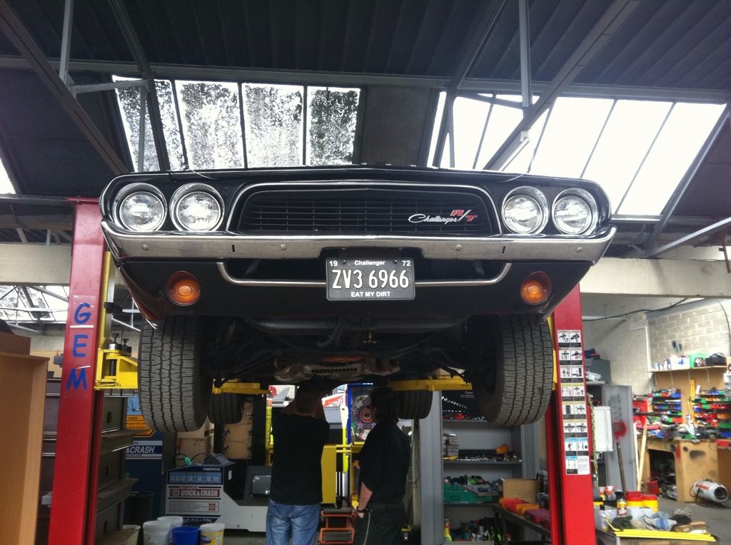
My '72 Challenger project
-
28-03-2014 12:05am#1Ok, so like most have said this is also a project thread I’ve copied & pasted from other forums I posted it in on the interweb & it covers my ownership both in Ireland & now here in Australia & it’s pretty long by now … Also something that will become very obvious to all very quickly is that I am by no means a mechanic & really haven’t got a clue what I’m doing here & most of what I’ve done I learned on the job, so I’m sure that there are better smarter more correcter ways of doing what I’ve done… but I’m having fun playing with it & that’s all that matters.
Right so lets start right at the beginning… this is how she looked the week I bought her & brought her home to my house in Hollystown at the time.. this house had no garage so our time living there post buying the Challenger was very short as we hunted a house with a garage big enough to take the car.

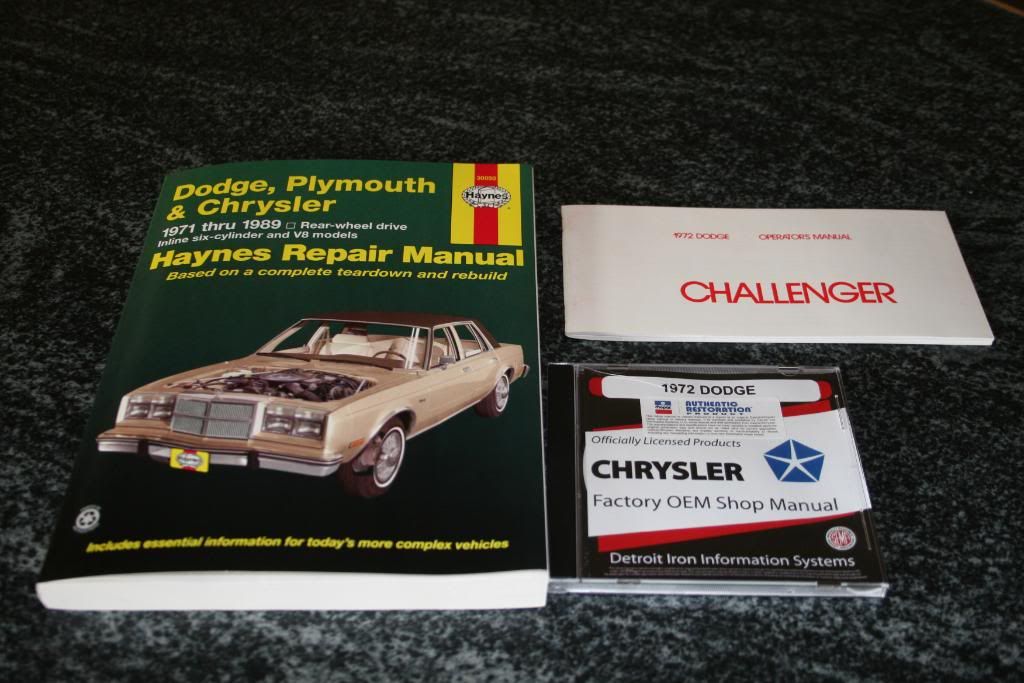
Once I had the car I started to put together a list of the things that I wanted to fix/change & I started to put together a bit of a plan in my head as to what I wanted from the car ultimately & that’s what the US call Restomod & I’ve recently ordered some big bits to kick that change off… but we’ll get to that in time when the pieces I’ve ordered get delivered. The car had a bad vibration when I bought her so I started down the path to find the fault & fix that, I pulled the driveshaft off to check the uni joints & they were very worn, so new uni joints where ordered as well as a new slip yolk… also the steering had a bit of play as you would expect from a 40 year old car & I tried to adjust it out with the built in shim adjuster but the box was too far gone, so I ordered a new quick ratio box for the car as well as some of the manuals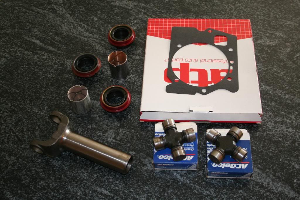

Some the first job was to pull the drive shaft off & have a look at the uni’s… well to say that they were stuffed is an understatement, they were so worn that the end that should be perfectly round looked like splined shafts the needle bearings had worn on them so much…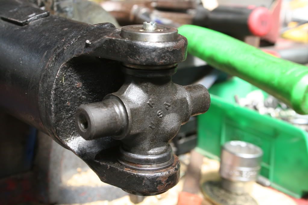
New uni’s where pressed in place to see if that would fix the issue, I had planned to swap out the slip yolk at this time also as I was lucky enough to have access to mate's lift to get easy access to the shaft… sadly the slip yolk they sent me was the wrong one…. So we just had to put the old one back in.. the new Uni’s made a huge difference to the car, but the vibration was still there, now just not as bad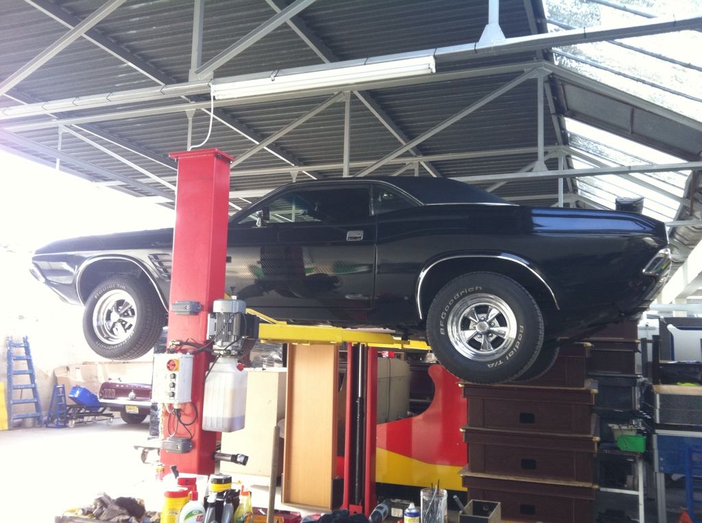
 17
17
Comments
-
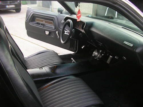
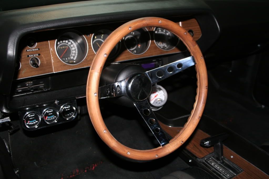
Then I decided to work on some of the simple little details that I felt would make the car what I wanted, I’ve always felt that sometime the simple small detail changes can make a huge difference to a car.. for example I really love the clean lines that my Challenger has from the side because a previous owner decided to remove & fill in both the front & rear side marker lights that a Challenger should have.. I just love how so many people have stared at her & said “it just looks different, I don’t know why it just does”… So I chose to replace the steering wheel which looked & felt like one from an 80’s arcade car racing game & I opted to go with a larger diameter Grant wood rimmed wheel, not only did it look much better now but the larger wheel made the steering feel lighter & easier at low speeds for parking & the likes
Then I decided that I just had to have the famous Pistol Grip shifter for my Challenger, in my mind this is an Iconic image for a Challenger… so out with the old
In with the new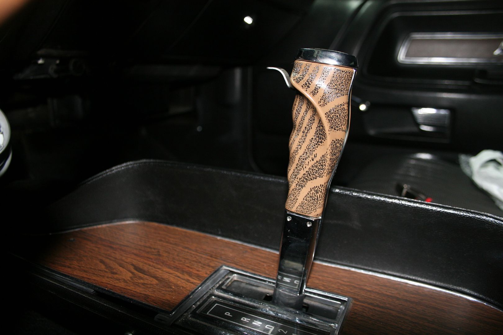
Another iconic image I always had of Challengers was the flip top fuel cap… but they stopped fitting them as standard from ’72 on.. so mine just had a flat cap… so off that went too
& on went the race inspired flip top
I then changed the plain black plates you can see in the first pics for a set of US styled plates… as I said, for me it’s the small details sometimes that outweigh the big ones
By now the correct slip yoke turned up in the post so it off to find somewhere to allow me access under the car to pull the shaft yet again, my mates lift was full of Boss Stang at the time so a pit was found

Now this improved the vibration even further but it was still there, so I went looking for someone to balance the drive shaft & tried another 3 places… all of them told me that they couldn’t help & that none of their equipment could test or balance a shaft like mine…. Now whilst under the car this time I noticed that the inside of the drivers side rear wheel was covered in oil.. looked like the axel bearings has shat themselves… so I decided that this was a job too far for my skills & I farmed this one out… A guy in central Dublin was suggested to me & I was amazed to find a workshop & nearby lockup filled with ‘50’s & ‘60’s American cars in central Dublin… for obvious reasons I’m not going to post up the location here.. but if anyone has an American car that needs work done PM me & I’ll give you a good tip..
So back in the air she went again 3
3 -
By now I had been doing a lot of driving in the old girl & I was feed up with the way the suspension was working, or not working as it was… so I ordered a shiny new set of adjustable shocks for her

Nice easy job, jack up a wheel at a time, pull the old shock off & fit the new one…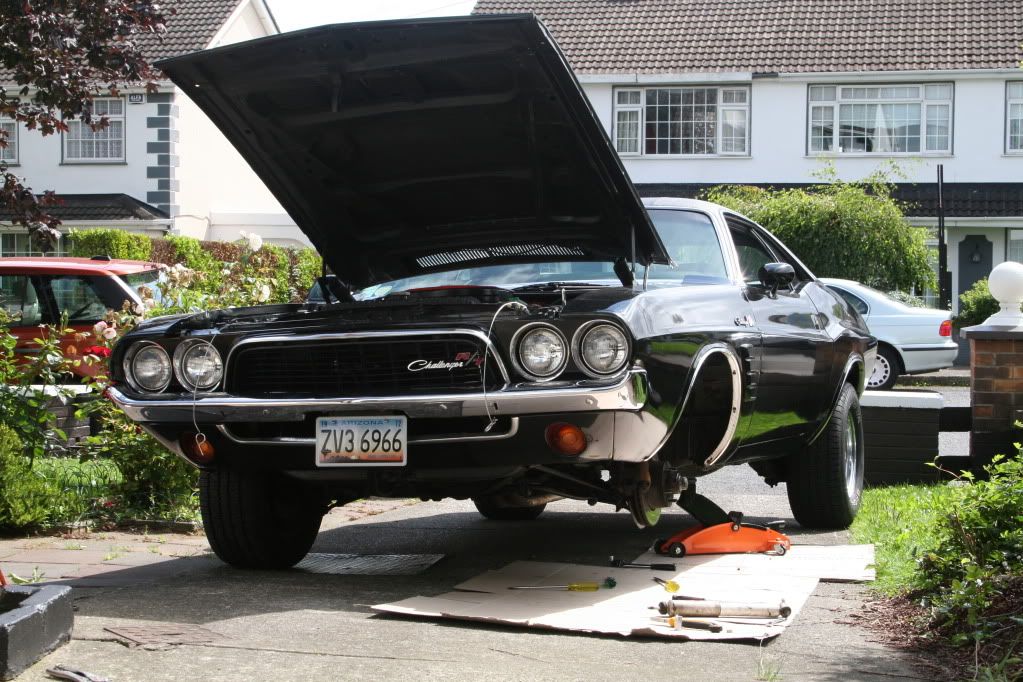
Old front vs new front
Old rear vs new rear
The new fronts made a massive difference & are fantastic I must say.. when the old rears where removed it was noted that they could not be compressed at all really they were almost solid, the new shocks even on the hardest of their 12 settings where way softer & this showed up the fact that the rear springs where shot too…. so a plan was hatched to replace them too, this hasn’t happened yet but the bits are ordered.. to give you an idea of what I’m doing google the Hoskitch E-Max Challenger..
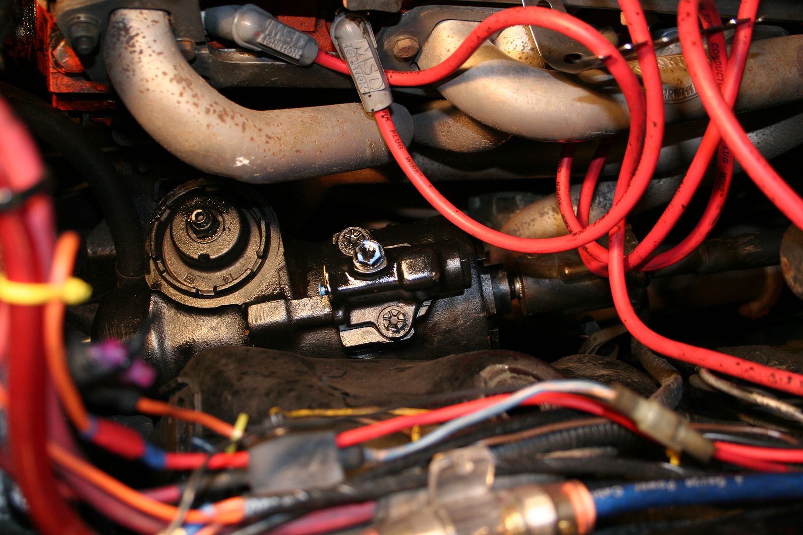
I went for a long drive to the beach one day with my brother & his Camaro & on the way out the M50 the car started to develop a misfire… so whilst we ate some chips on the beach we pondered what that might be
We checked all the leads & noticed that they were badly cracked really & probably should be replaced… then once home I did a bit more poking around & found a cracked plug to be the issue
So I replaced the plugs all round & ordered a new set of leads to make up

Now putting the stupid clip ends onto the leads to make them up is a complete frontbottom of a job if your using the crappy little tool that they give you in the kit that has to be hit with a hammer… but it was all I had so it was round to a mates place for a helping hand to knock up some new leads.. how he still has all his fingers is anyone’s guess. I’m not happy with the lengths of the leads & I was out shopping today & I bought the correct professional crimping tool & I plan on recutting all the leads & making them up fresh again1 -
A few weeks later on another long drive she developed a new noise… I knew straight away what it was, once of the exhaust gaskets had blown… so back on the interweb & a new set ordered.. when I pulled the headers off there was so little of the old gasket left it wasn’t funny..

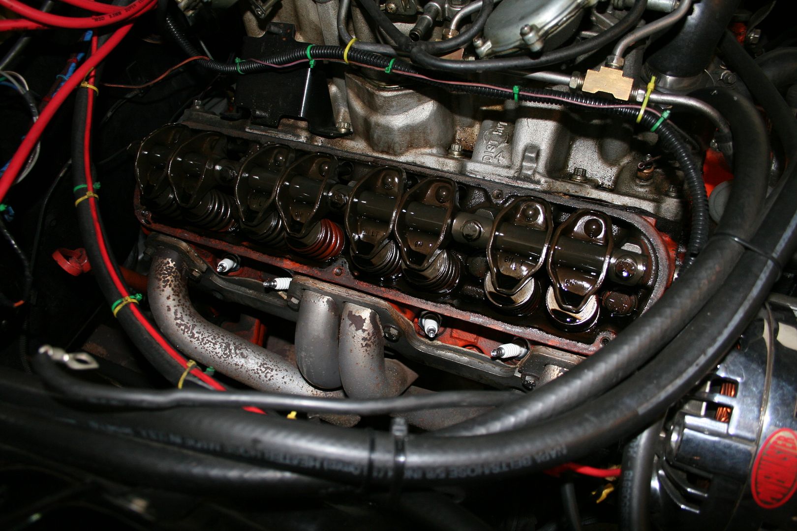
Doing this job whilst leaving the exhaust under the car all hooked up & leaving the engine in was actually very tricky, there isn’t as much wiggle room in the engine bay as you find with a Chev or a Ford of the same era.. whilst I was doing the exhaust gaskets I decided to also do the rocker cover gaskets & to retighten the rockers down to ensure the correct lash was set
That was the last of the work carried out on Irish soil.. I then just drove here the rest of the year before making the decision to leave this fair isle & return back to Melbourne, these are the last pics of her ever on Irish soil…

I took this one, just after I backed her into the container… my last view of Ireland from behind the wheel..
All tucked up for the trip
She must be the best travelled Challenger in the world now… started life in the US, then move to England, then Ireland & now in Australia…. Now whilst I was a bit cramped with her in my garage in Firhouse
I have no such issues with my new house here in Melbourne
So now this has us up to date with her arrival in Australia late last year… I’ll continue the story in a few days of what’s been happening & what’s been done & what’s been planned for her here down under2 -
So a few months passed where I was in Melbourne but the ship that my containers where on was stuck in Europe.. so what should have been 6 to 8 weeks without my stuff become a little over 12 weeks in the end, but all my stuff got here in one piece so I guess I should be grateful of that. The Aussie customs guys where a complete joke, even though both of my cars had been professionally cleaned before going into the shipping containers & when I say cleaned… they were spotless inside & out & undersides & under bonnet… But they deemed that they were dirty & needed to be steam cleaned before they could be released to me... so the costs I was given was:
Steam clean the cars at $656.50 per car x 2 = $1,313.00… yes you read that right 1063 Euro’s to steam clean 2 cars!!!!… clearly they need to get some polish lads over here quicksmart
Towing to & from accredited quarantine treatment location $338.00 per car x 2 = $676.00, as they hadn’t cleared customs I couldn’t drive them to be cleaned
Then the one that really made me feckin mad was a quarantine re-inspection fee of $304.20… yes that’s right after making me pay to get them steam cleaned at the one & only authorised cleaner in Melbourne I then had to pay for them to check that feckers work!!!! Surely if he’s your chief steam cleaning man then he shouldn’t need his work inspected… & for $1,313 I expect the cars to be cleaner than a fecking F1 car..
Oh & how did the cleaning work out I hear you ask…. They came back dirty… yep, they went away clean to be cleaned & came back covered in crap!!! I was going to scream blue murder at the time, but the guys in the warehouse said that if I complained that the cars where dirty then I ran the risk of the inspections guys demanding that I get them cleaned again… so I just took the cars & left..
I’ve since found out on several US car forums here in Australia that it is a well know scam & every single US car brought in gets this special revenue raising “wash”.. they reckon if the Range Rover had been on its own it would have been fine, but as they know how much money can be made importing US Muscle they sting everyone with this bull
Luckily the import taxes where a lot less than I was expecting & as such the total expense for the whole thing was less than I had budgeted for anyway..
I’ve been driving her very little the last few weeks as she’s not registered here yet… I have to get an engineer to sign off that she’s compliant to all the Australian design rules for 1972.. so she needs a bit of work:
The front lights need to be swapped as you’d expect as they point to the wrong side of the road, so I’ve stripped the front down.. interesting to note the colour of the light buckets..
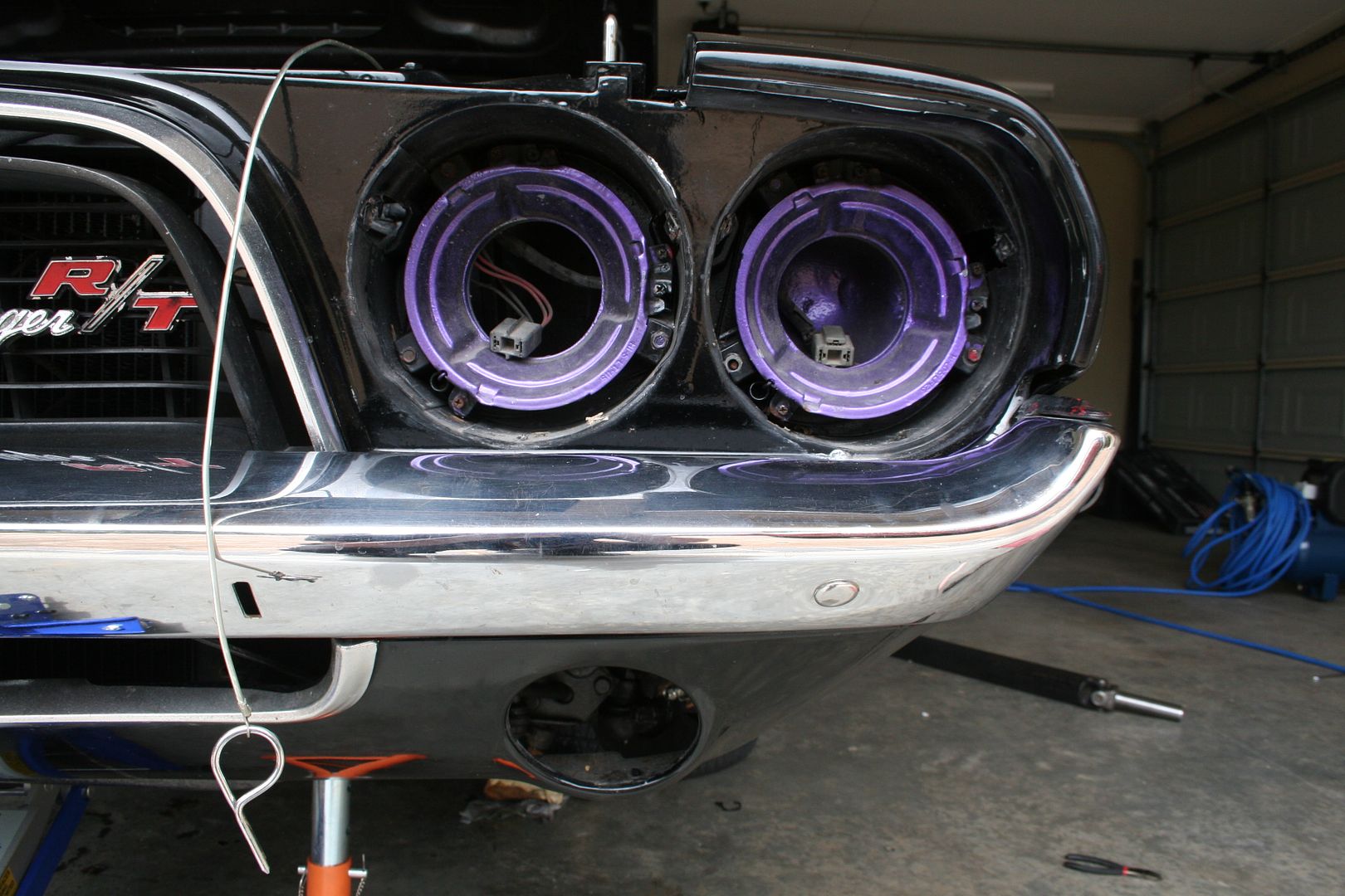
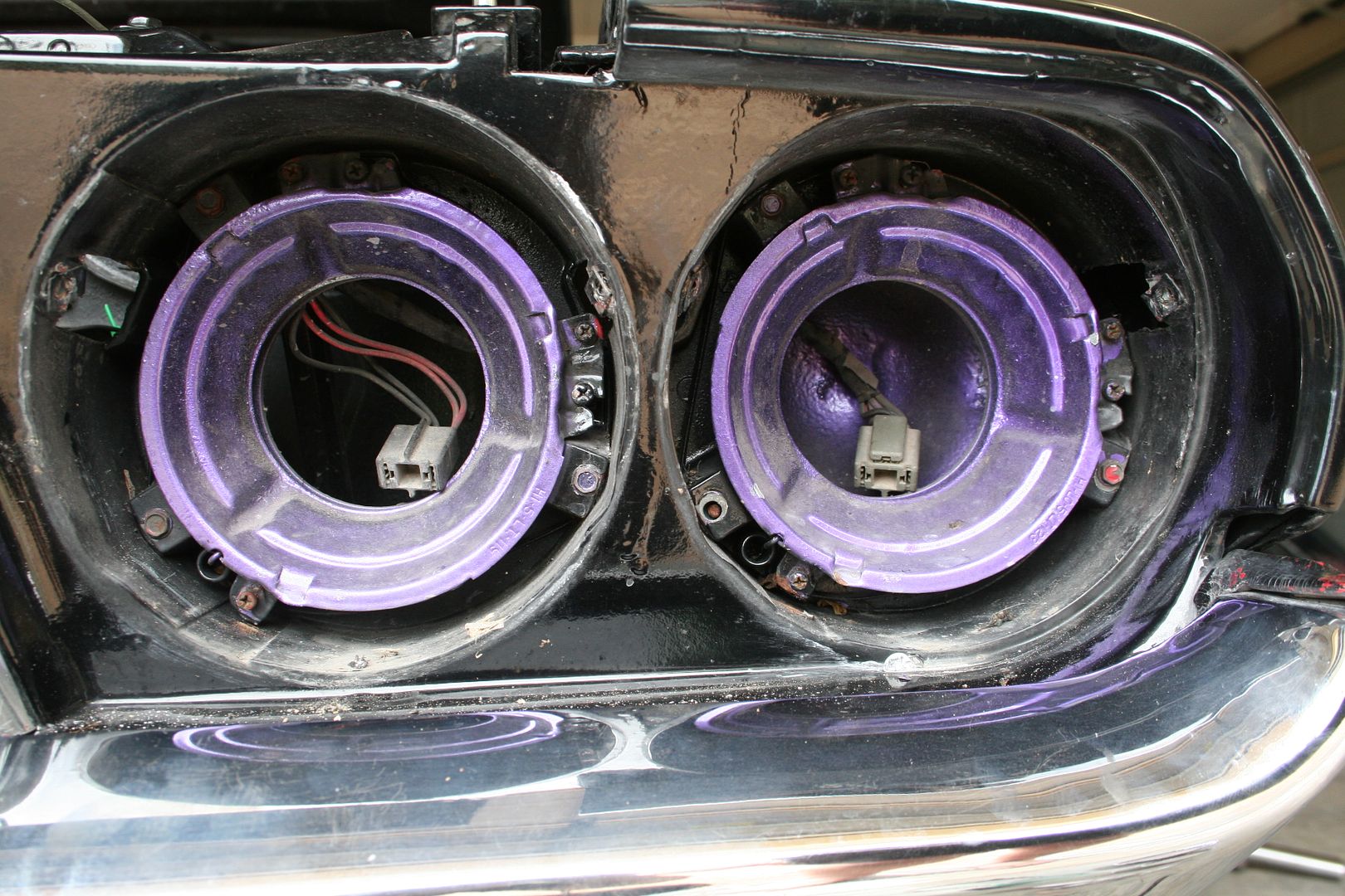
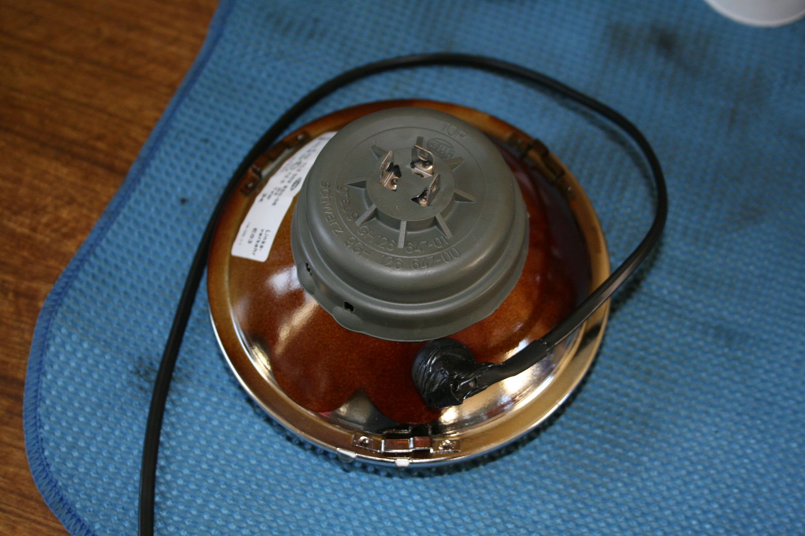
Then I got a new set of Hella H4’s to go in
The issue that I now faced was that the small park light that’s built onto these sticks out to far to go into the bucket without me doing some surgery to the buckets.. something I was not keen on at all… after some further thinking on that, I made up a set of LEDs for them that when fitted almost sat flush with the light & could be just squeezed in without having to touch the buckets at all… happy days..
So now I have bright driving lights that point the right way too..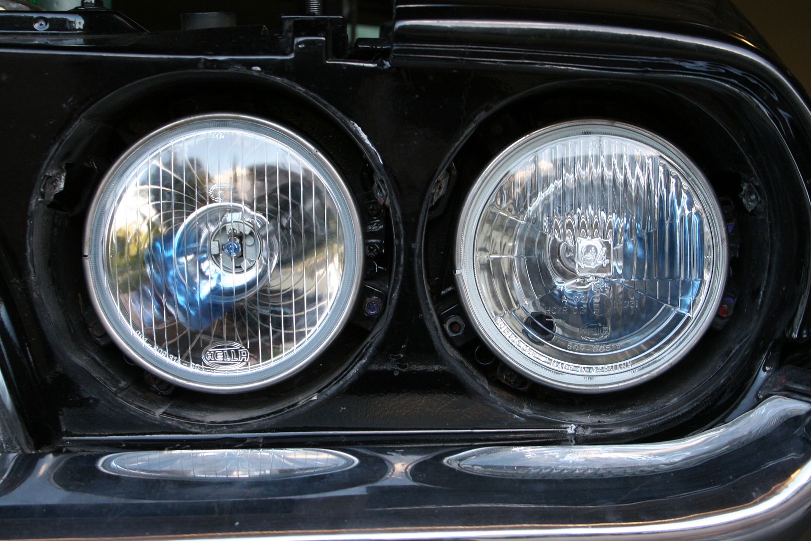
It looks like I also have to rework the rear lights as the US style blinking brake light may a no no here for a ‘72.. so I may have to rewire the car so that the reverse light is the indicator, having two orange lights for the reverse lights is fine (my XB had that from factory in ’75)
 2
2 -
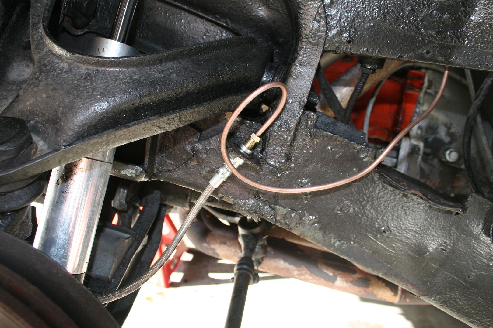
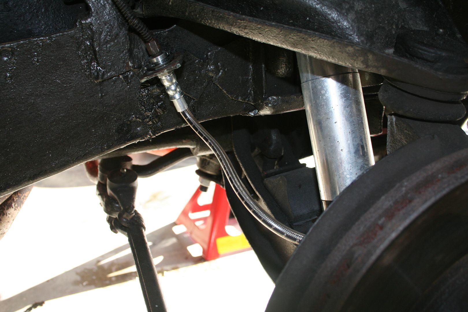
The brake hoses are all have different dates stamped on them & two of them have no standards stamped so they have to go too…

So I got a set of braided hoses made up to replace the rubber ones


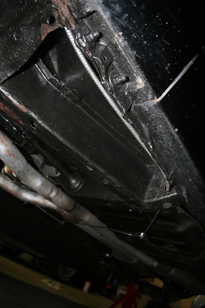
I’ve pulled the tail shaft out again, as I was never able to find someone who could balance it correctly in Dublin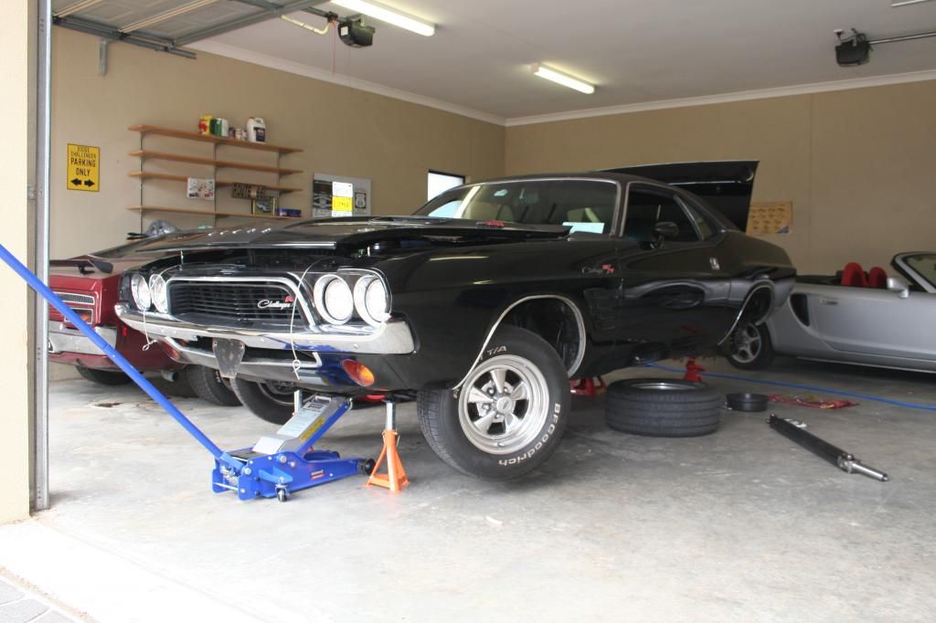
Came back last week from the shop & they confirmed that it was out of balance & it shook their machine at around 2600.. which was pretty spot on to what I was sure was going to be the answer from them… so the newly balanced & painted shaft was back 1
1 -
Advertisement
-
I’ll need to swap back to the original wheels when she’s being engineered as the Cragers are a two piece wheel & they were made illegal here in the 80’s as they can fall apart if you hit a bad enough pot hole (or some I’m told)
So this is how she’s sitting in the garage now for the last few weeks, as more bits are ordered & I find more things that really need to be fixed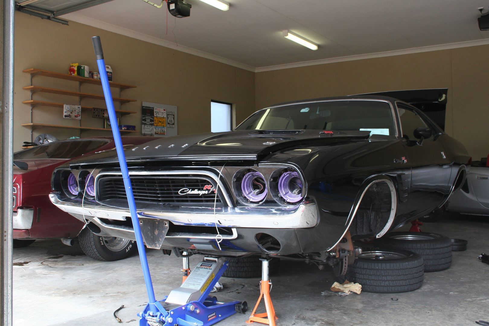

The other thing that I need to do is to fit some extra mufflers to the exhaust as she has to pass a noise test at 3300 RPM & she’s miles over right now… will be fitting something that can be removed after she’s got her plates… sadly I can’t fit cut outs as they are very illegal & they can confiscate your car if your found to have them fitted… where as if I just refit a load exhaust it’s just a fine & I get 30 days to fix it.
I also need to replace the seat belts, the Chally has a set of two piece belts in the front, this means that you can wear them as a lap only belt or as a 3 pointed belt, but as the shoulder part is not retractable they have to go

Well Australia was ahead of it’s time in ’72 as they required proper drop link 3 point retractable belts in the front & 3 point retractable belts in the rear.. I’ve found a place that makes them to suit.. so I’ll be getting a set soon & bolting them in, the fronts will go straight into the existing holes, but as the rears are lap only I’ll have to fit some mounting brackets in the rear parcel shelf & both the belts to them.
I also have to pull the dash to replace the headlight switch as the one in their now only works for the park lights, to turn the lights fully on is a 2nd switch under the dash… I was lucky to find a NOS headlight switch on the net & that’s sitting on the bench in the garage along with the NOS windscreen washer bottle & pump that I need to fit as she’s not road legal without one.
NOS windshield washer kit
I also have a new handbrake cable to fit that came with the car when I bought her... 1
1 -
I was making good progress on the project in the Skunk Works garage, however between lots of travel for work, just general being busy at work & the fact that I keep making the list of things I want to do to the car bigger & the resultant delay that adds not only in work effort but in the weeks it can take for parts to turn up from the states.. I’m still a ways away from having this all done. On the bright side I’ve been having a ball doing the work, it’s been years since I did any sort of big project work on a car & I’d forgotten just how satisfying it can feel when you’ve replaced or repaired something on your pride & joy.. now I’ll be the first to admit that none of what I’ve done is rocket doctorary in any way shape or form but I still get a warm happy feeling at the end of a long day in the garage when I can look at something & say, I did that… it’s a great way to unwind from my normal stressful job & my incredibly understanding better half has even taken to joining me in the Skunk Works to work on the car & I don’t mean just handing me tools, she’s in there getting her hands dirty, she is particularly fond of using the air tools I’ve found.
Anyway, back to the car.. so the lights are now sorted, well on the outside I still have to pull the dash apart to replace the headlight switch as it doesn’t work anymore & then whilst I’ve got the dash apart I have now also bought a new set of gauge lenses as the ones on the car are so badly scratched & foggy now that you can’t really see the gauges at all.. I’ve also ordered a new Quartz movement kit for the original Borg dash clock, these all failed in every Challenger & Cuda ever made, so I’m not going to pull the dash until I have the clock parts too & then I’ll do all 3 repairs at once.
NOS headlight switch
New Gauge cluster lenses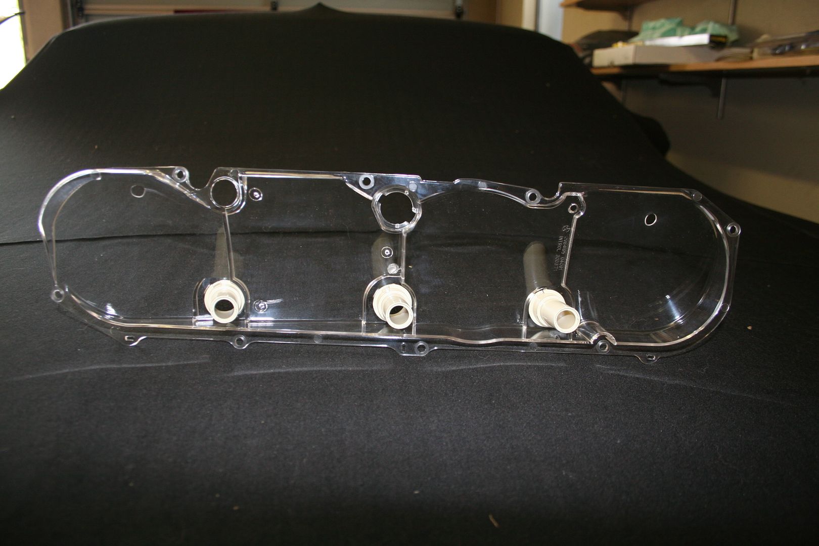
The next thing I figured I’d sort was the windscreen washers, as you saw in a previous post I found a NOS kit & bought that, now all I had to do was fit it into the engine bay & wire it up.. simple.. well no not really the space where it should live is now occupied by my vacuum tank for the brake booster..
A quick trail fit & it actually looked like it might just fit if I removed the vac tank & installed the washer reservoir first & then reinstalled the vac tank next to it
Once I had the vac tank off I noticed that it was rusting a lot around the central join it would need some cleaning up before I put it back in, later that day I happened to be at a car show & I spotted these for sale, so I figured you can never have enough chrome bling in the engine bay of a muscle car, so no need to tidy up the old one now.
Sorry for the pic quality or lack thereof but the camera focused on the wrong point… but you get the idea
The metal pipe that you see dangling in the air is for the charcoal canister that the car would have ran from the factory for emissions, as the canister is long gone & there is no room for a new one, I removed the pipe.. see just like Colin Chapman, I’m applying the lotus principle of adding lightness where I can… 1
1 -
Next on the list of things to fix was to fit the new handbrake cable set that I got with the car when I bought her, now this sounded like a nice simple task, as the only parts of the old cable set-up that where still on the car was the flexi cables that connect into the rear drums & the flexi cable that runs up & into the footwell of the car & connects to the foot pedal that operates the E-Brake as the US would call it.
When I was ordering some new parts from US, I decided to get the full set of manuals for the car, so I have the Chassis, Body & Service manuals now & a complete set of the electrical diagrams.. should come in handy
The old cable had rusted itself to the car where it passes through the bodywork into the footwell, the old grommet had long perished & getting this old cable out took a lot of profanity to do the job properly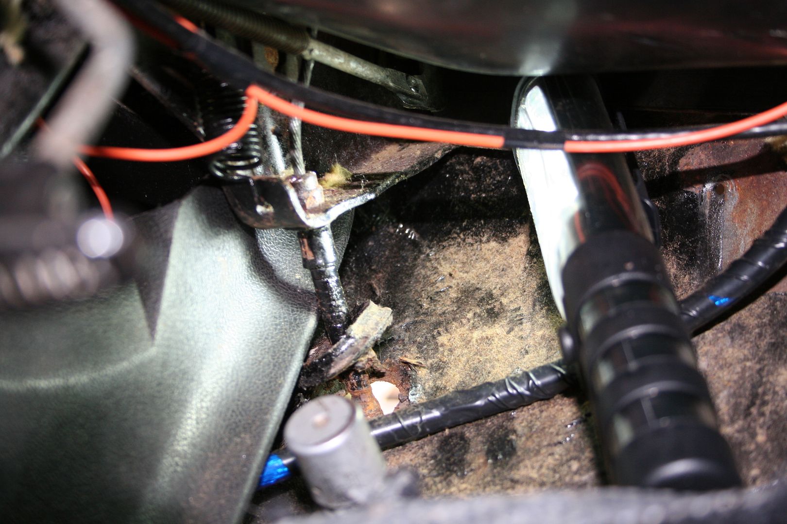
Old cable vs new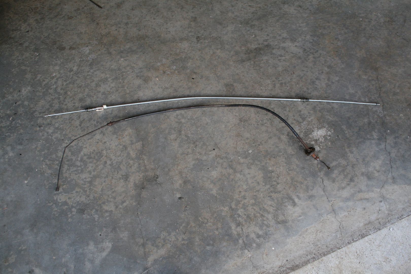
I went shopping for some new grommets so when I installed the new cable section into the footwell the cable would be protected somewhat, once I’ve finished & I’m sure the cable is not coming out again then I’ll fill the gap with some sealer to stop crap getting into the car, but until I’m 100% sure the cable doesn’t have to come out I’ll just leave her as is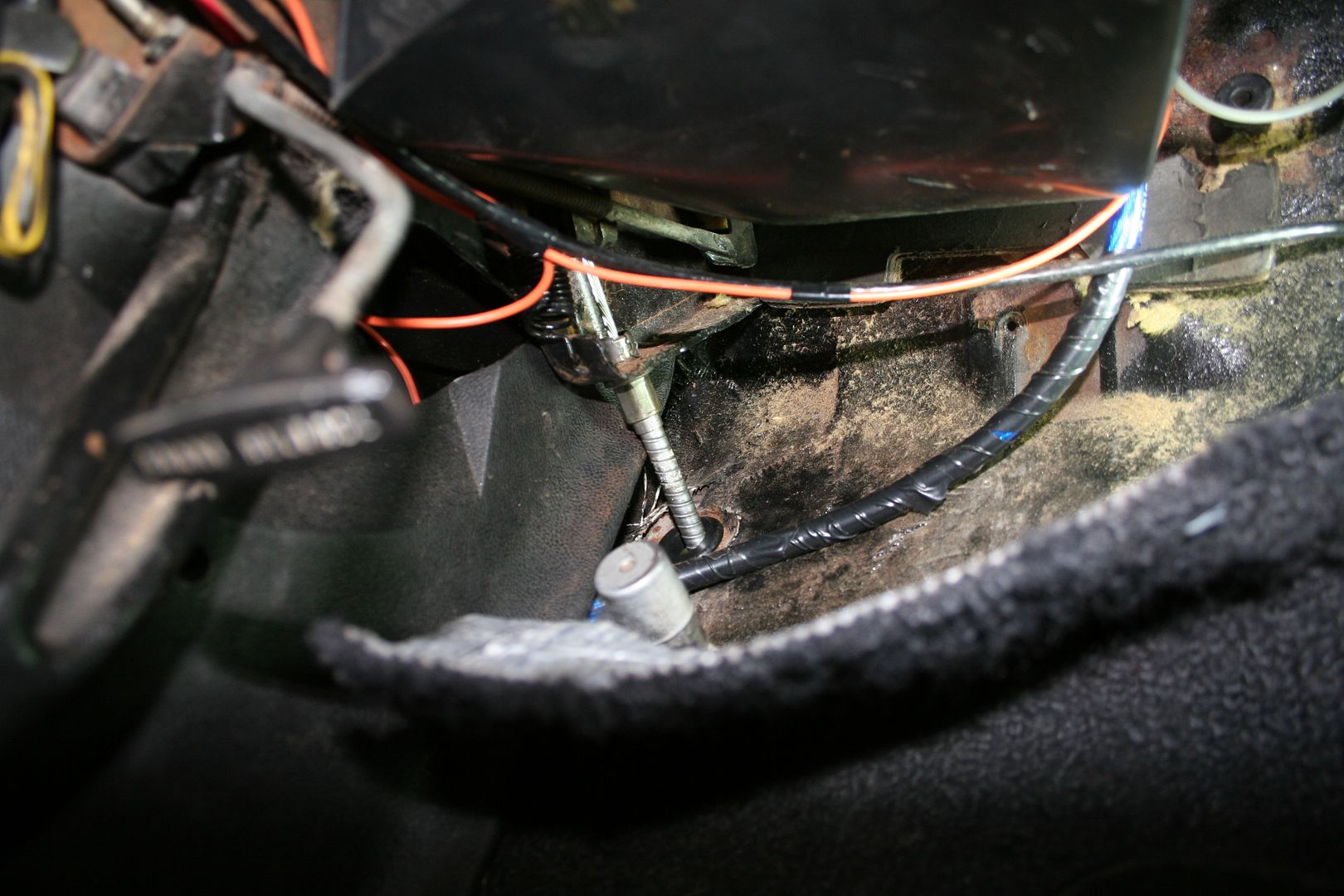

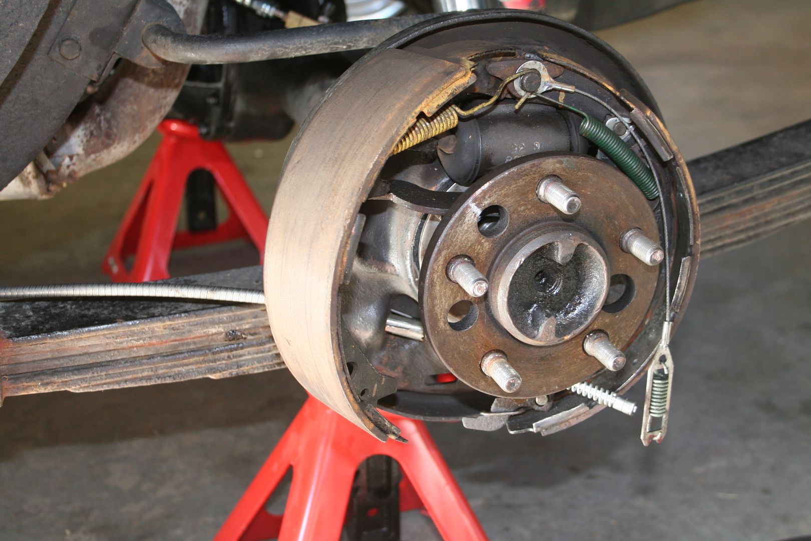
Then it was onto the rears, I had to dismantle the rear drums to disconnect the cable from the handbrake adjuster in the drum
I hate undoing these stupid clips that hold on brake shoes, inevitably one always ends up shooting off into the furthest corner of the garage as the pliers slip off at some stage
Once undone I then removed the old cables, they had now set hard into an immovable shape, this did not ease the removal of them at all oddly enough
 0
0 -
Working with shiny new parts is always a dream, they are clean & tend to fit up nicely, installing the new cable ends was a breeze

Then I just had to install the adjuster bar & the actual cable part of the kit, I suspect that it’s actually supposed to be routed over the top of the exhaust but the exhaust on this car is practically touching the floor so there is no room at all to do it that way.. when I replace the exhaust I’ll sort this then, for now the car has a hand brake as the law requires to get her on the road & it works.. so job done.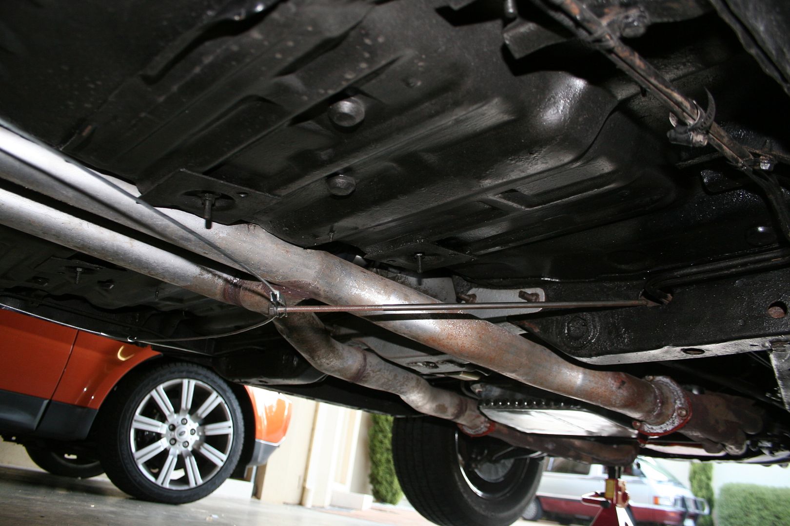
If you look at that picture above you’ll see two fuel lines running the length of the car, one of them is the real fuel line & the other is a dummy as it’s not connected to anything at either end, I’m guessing that this is a safety device to confuse anyone trying to cut a fuel line on my car.. again in the guise of adding lightness & removing crap that’s not needed I’ll rip that off later.
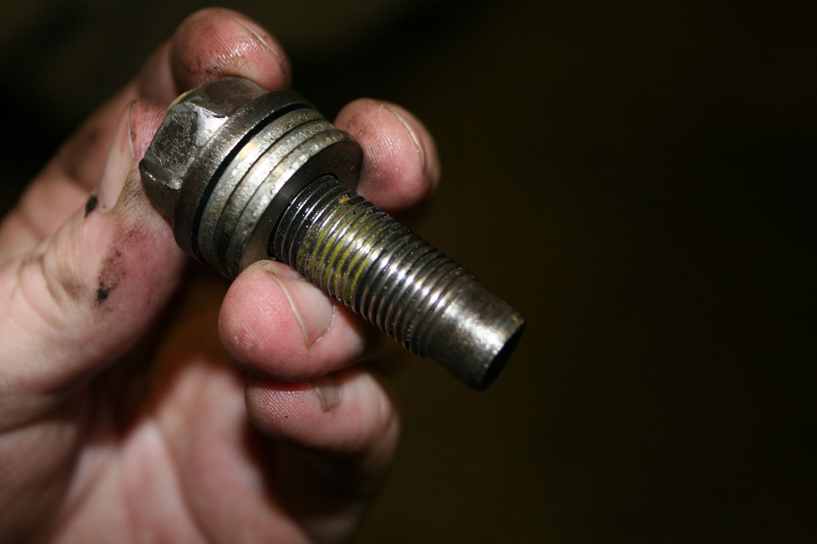
Whilst working on the handbrake cable I decided to finally get around to fixing the very annoying leak that she has from the transmission, upon closer inspection I can see that there are two distinct issues here, one is that some prior owner damaged the drain bolt & rather than replacing it or fixing it opted for some NASA spec silicone to do the job.. this clearly hasn’t worked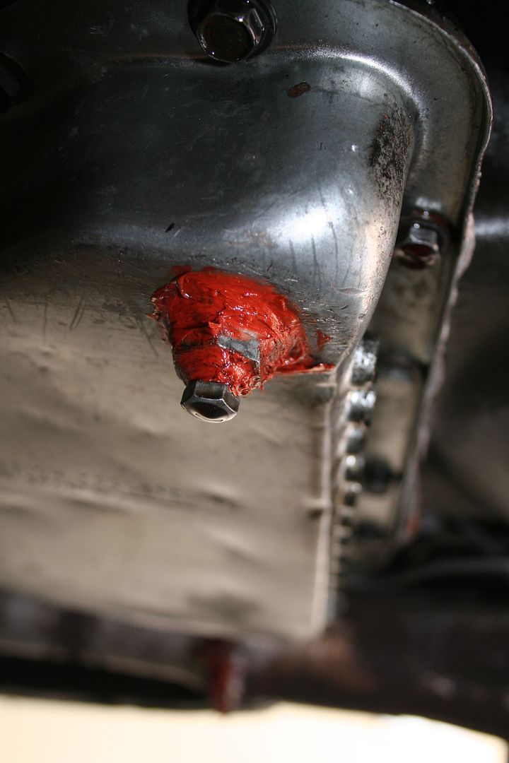
Also they have (I’m assuming it’s the same captain silicone responsible) over tightened the bolts on the transmission pan & this has crushed the gasket & pushed it out the sides.. sorry for the blurry pic, but if you look at the bolts to the right of the in focus bolt you can just make out where the gasket is totally stuffed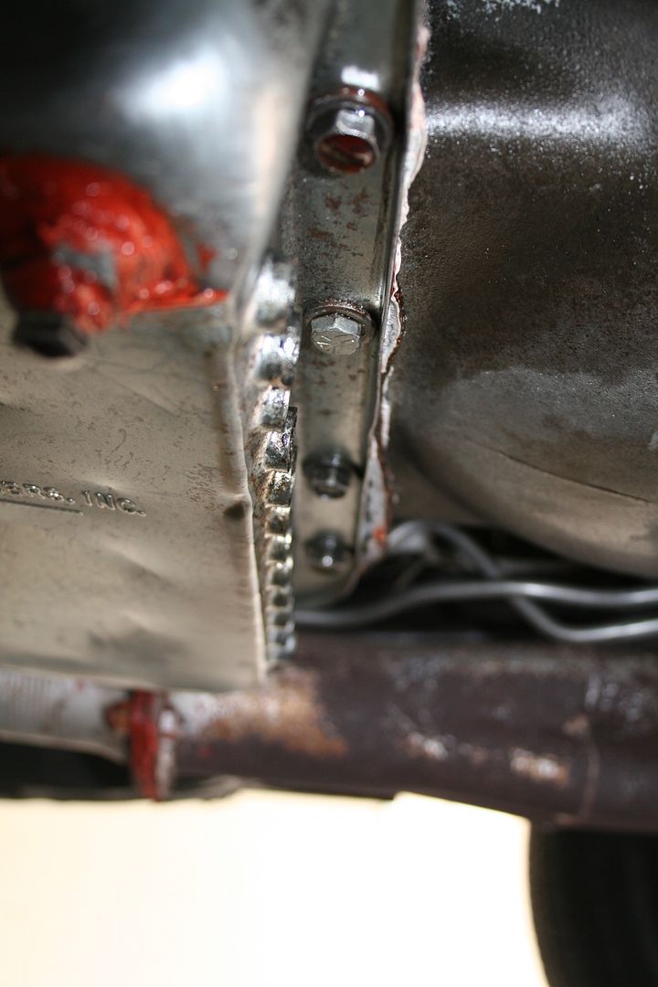
I had bought a new pan for the car ages ago, but had never gotten around to fitting it as the only axle stands I had in Ireland where too small to actually get under the car properly to be able to comfortably work on her, so off came the old pan, you can see now that the old gasket was fully stuffed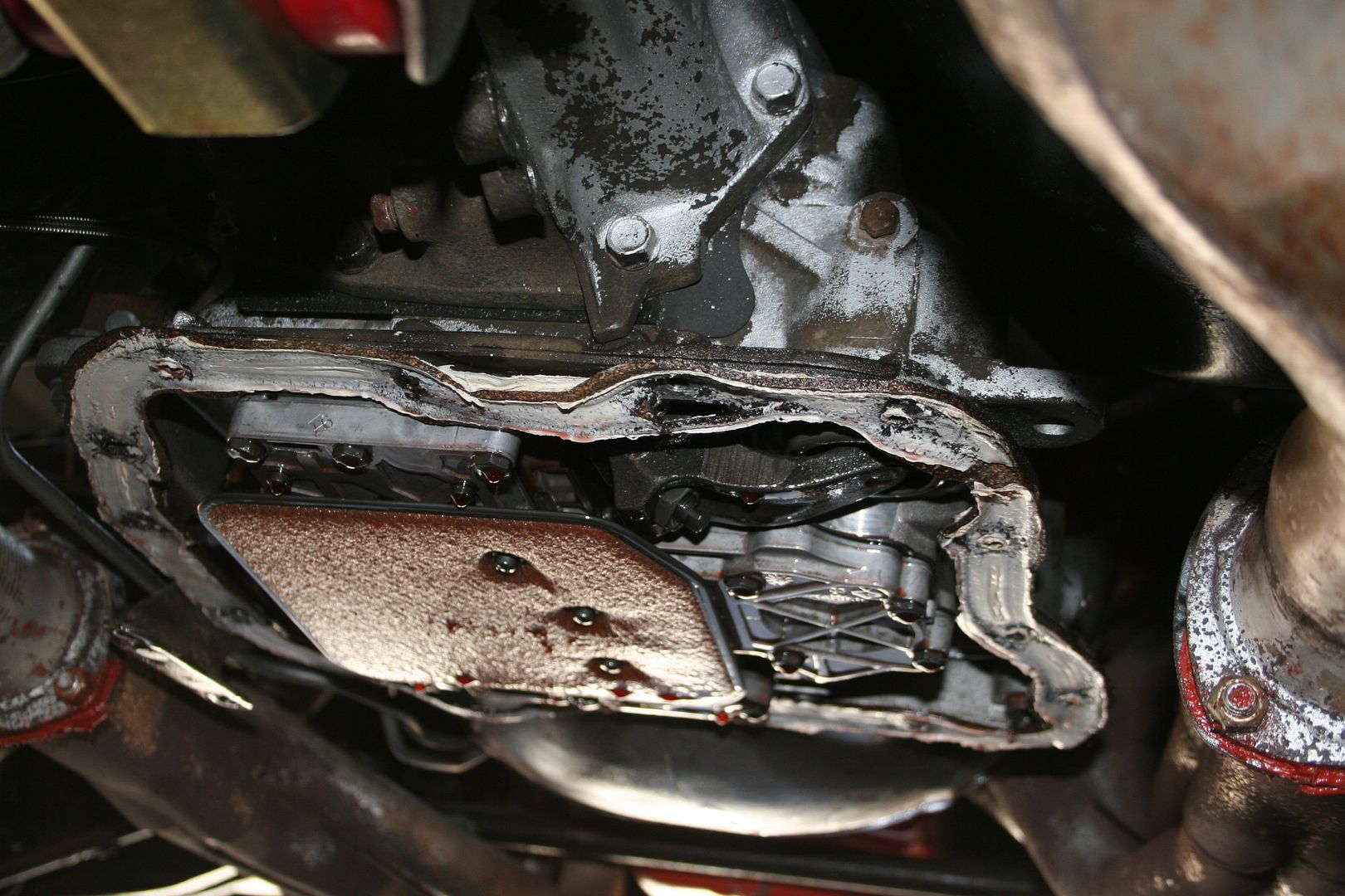

Once the gasket & the filter where removed I cleaned up the internals to make sure that there was no crap in there
The new pan that I have is a deeper pan that the one it’s replacing so I had to fit a spacer block for the new filter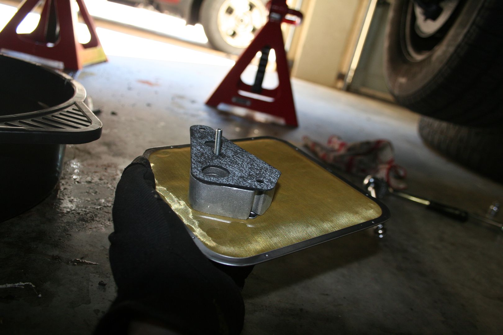
 0
0 -
Job done

The old pan is a fascinating design that I’d never seen before, it actually has cooling channels that run through the base to act as heat exchangers for the oil.. very nifty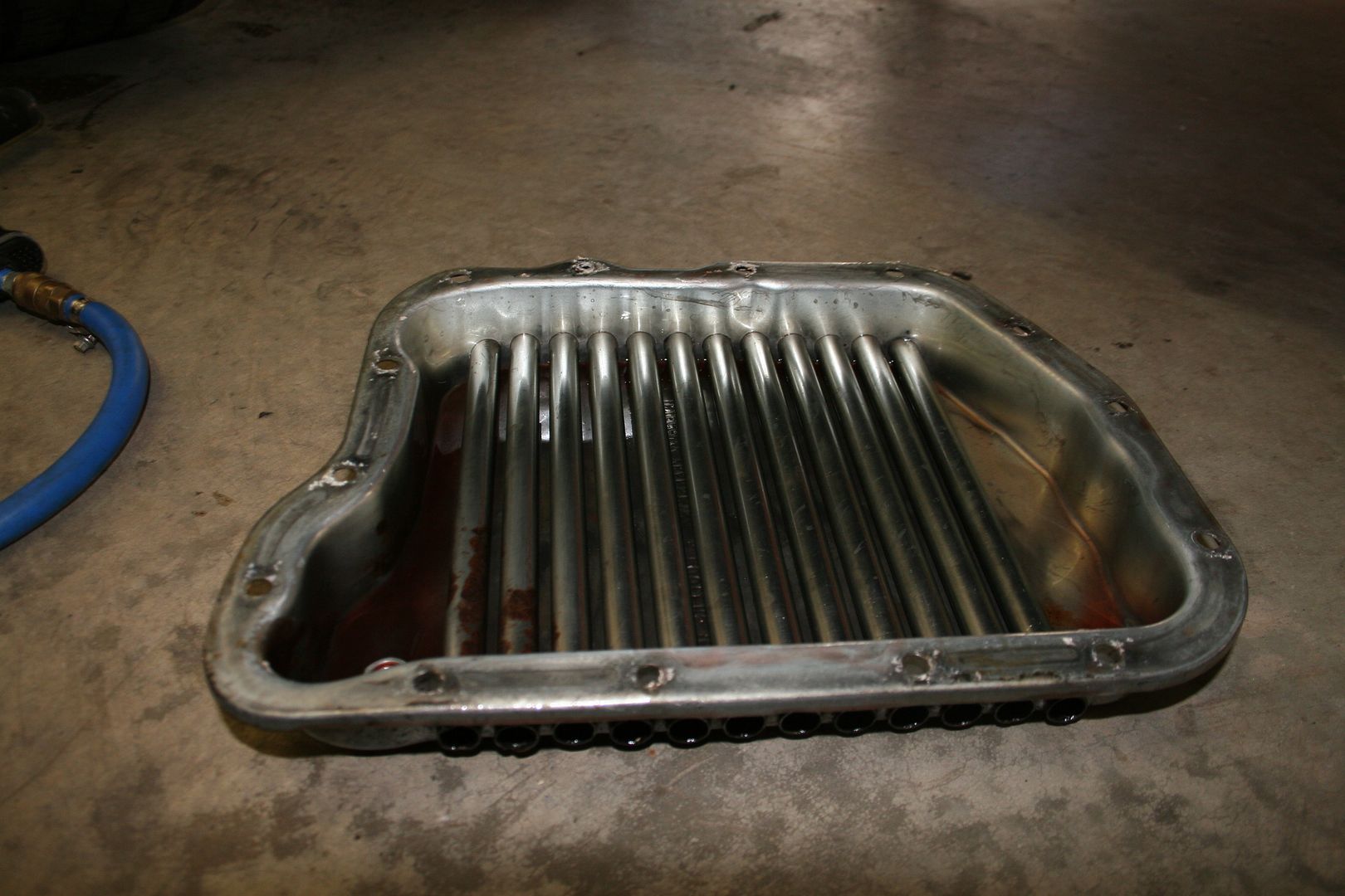
After cleaning off the drain bolt I can see that it sits in a plastic retainer & the whole thing is actually free to spin… this doesn’t seem like the best design in the world for being leak proof if you ask me

Still I might see if I can get someone to weld it in place so that it is then leak free then I might look to reuse it again as it does get bloody hot here in Melbourne.. although she does have a front mounted trans oil cooler fitted already so she should be fine I guess.
I was showing the car off to a mate the other week & he wanted to hear how load she is, so even though she’s up on stands being worked on we fired her up & smiled at that lovely lumpy idle that she has, his girlfriend was sitting in the car & we told her to give the load peddle a tickle & she did… what I then saw chilled me to the bone.. the fuel line that runs up along the engine had perished so much that every time she blipped the throttle it shot a small jet of raw fuel just past the back of the alternator… NOT good.. so we shut the car down right away
With the alternator removed you can see where the fuel has been spraying & then collecting grit & general crap on the front of the engine
So now I had a few options open to me to fix this, I could just replace the hose that was perished with new hose or I could run a metal fuel line like I did on the XB when I was cleaning up that engine bay
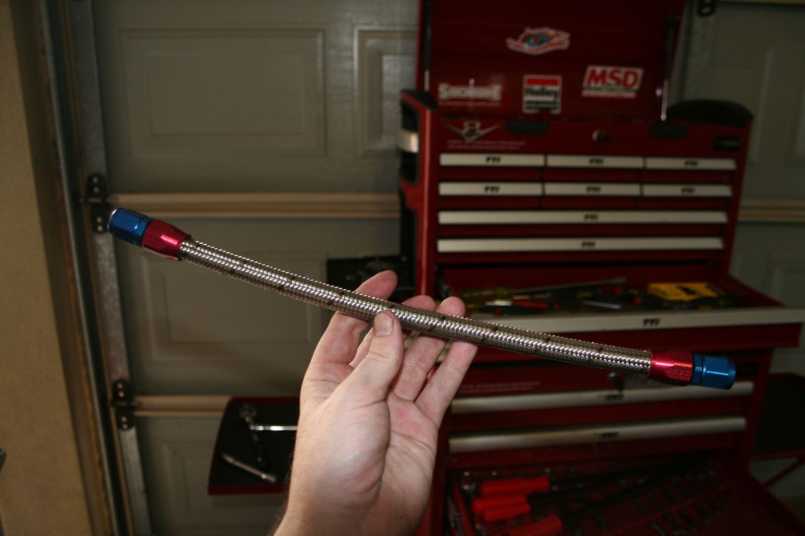
But I didn’t want to do that as I was never mad on the idea of having the fuel run that close to the block for heat reasons anyway, so I figured that I’d re-route the fuel line so it was clear of the engine.. I also decided not to go with rubber tube or with a metal hard line, I decided that I would teach myself how to make up lengths of braided hose & so it was off to the Interweb for an Earls catalogue to order bits from… so I sketched out what way I would run the line & measured it all up working out what adapters & ends I’d need along with an inline filter & enough length of braided hose for me to make up the lengths I needed… it’s amazing how such a small amount of shiny parts can cost so much.. but I was very happy with how they looked.
A closer look showed that a previous owner had done a fantastic job at rounding off the nuts that hold the lines in place & based off the excellent job that the silicone was clearly doing on the transmission pan they opted to gunk these up too..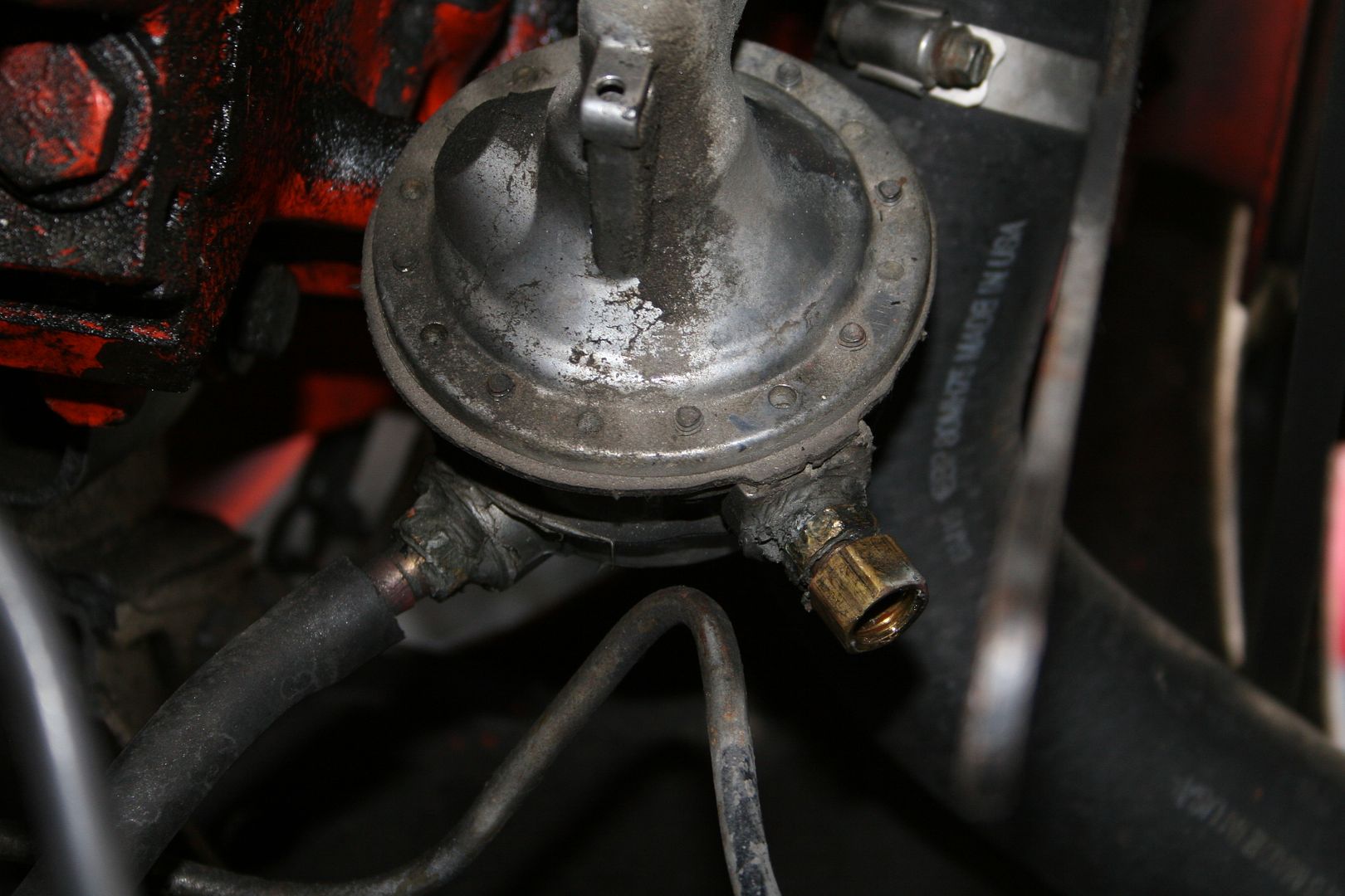
 1
1 -
Advertisement
-
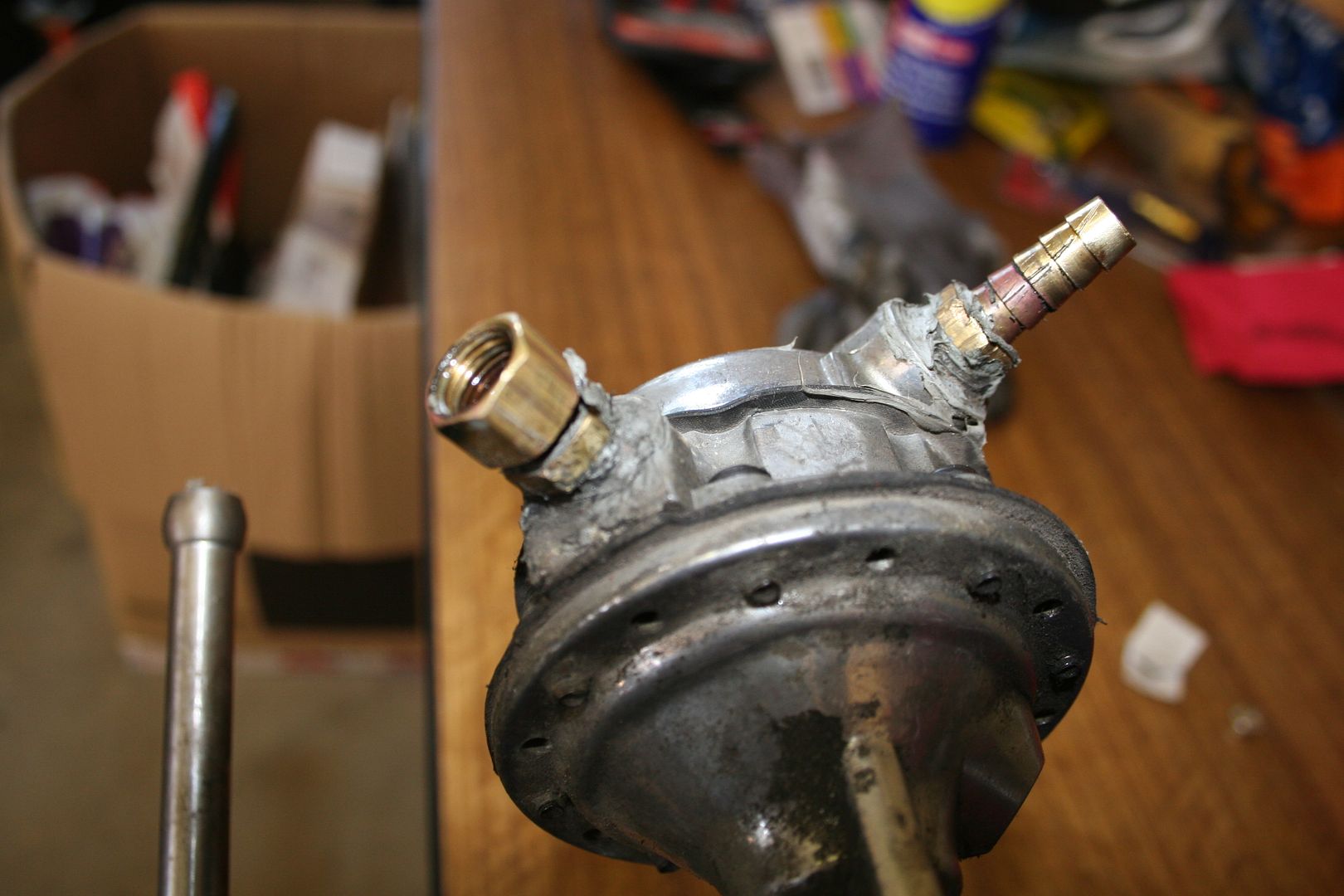
So off I went & I bought a shiny new Holly pump to replace the old one, I opted to use Teflon tape to help seal my new fittings on instead of covering the outside with silicone.. madness I know

New vs old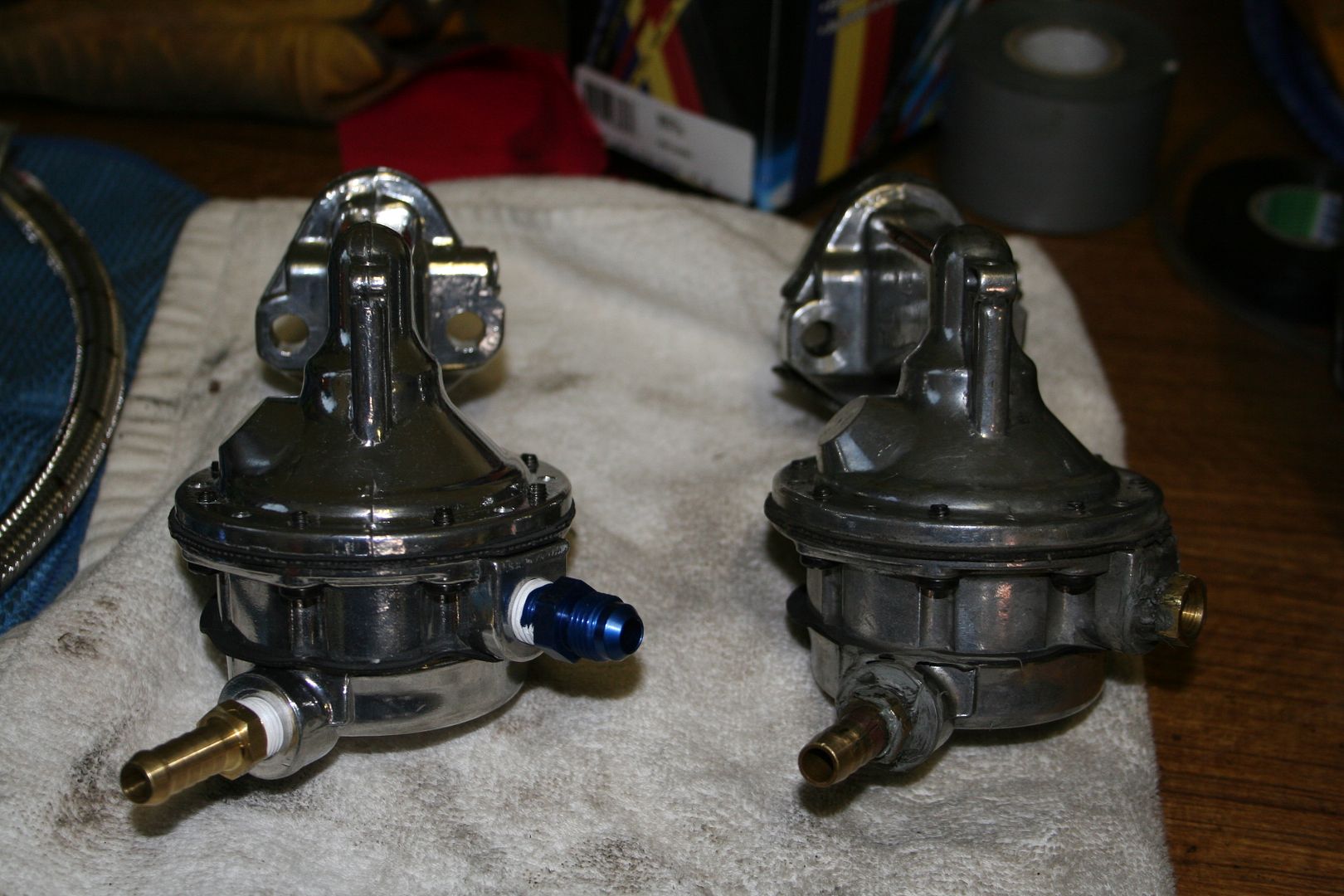
I would also now have clear access to clean off a whole section of the engine that I couldn’t get into before.. 0
0 -
I did a bit of research on the Interweb as to how to assemble up a braided line with Earls AN adapters & it’s luckily very simple (as evidenced by the fact that I was able to do it) When I got my length of braided hose the end wasn’t exactly neat & ready to be used

So I was going to have to cut the end off & make a nice neat end to work with, now there are a few methods listed out there.. the actual people who make the braided hose say to use a very sharp chisel & block of steel to guillotine cut the hose, I didn’t have said chisel & also I was pretty sure that that was a sales ploy from them as I would no doubt have turned my lovely new braided hose into a flat mash of rubber bits embedded with lots & lots of mushed steel strands… the other two options are a hack saw & finally a cut off wheel in a grinder of some sort… the hack saw sounded like manual labour to be & not nearly as much fun as the grinder option. I started by locking the hose in a vice, I don’t own a set of soft jaws for my vice so I used a cloth to stop me from damaging the braided hose, I then taped up the end of the hose very very tightly to stop the steel strands from moving as I cut.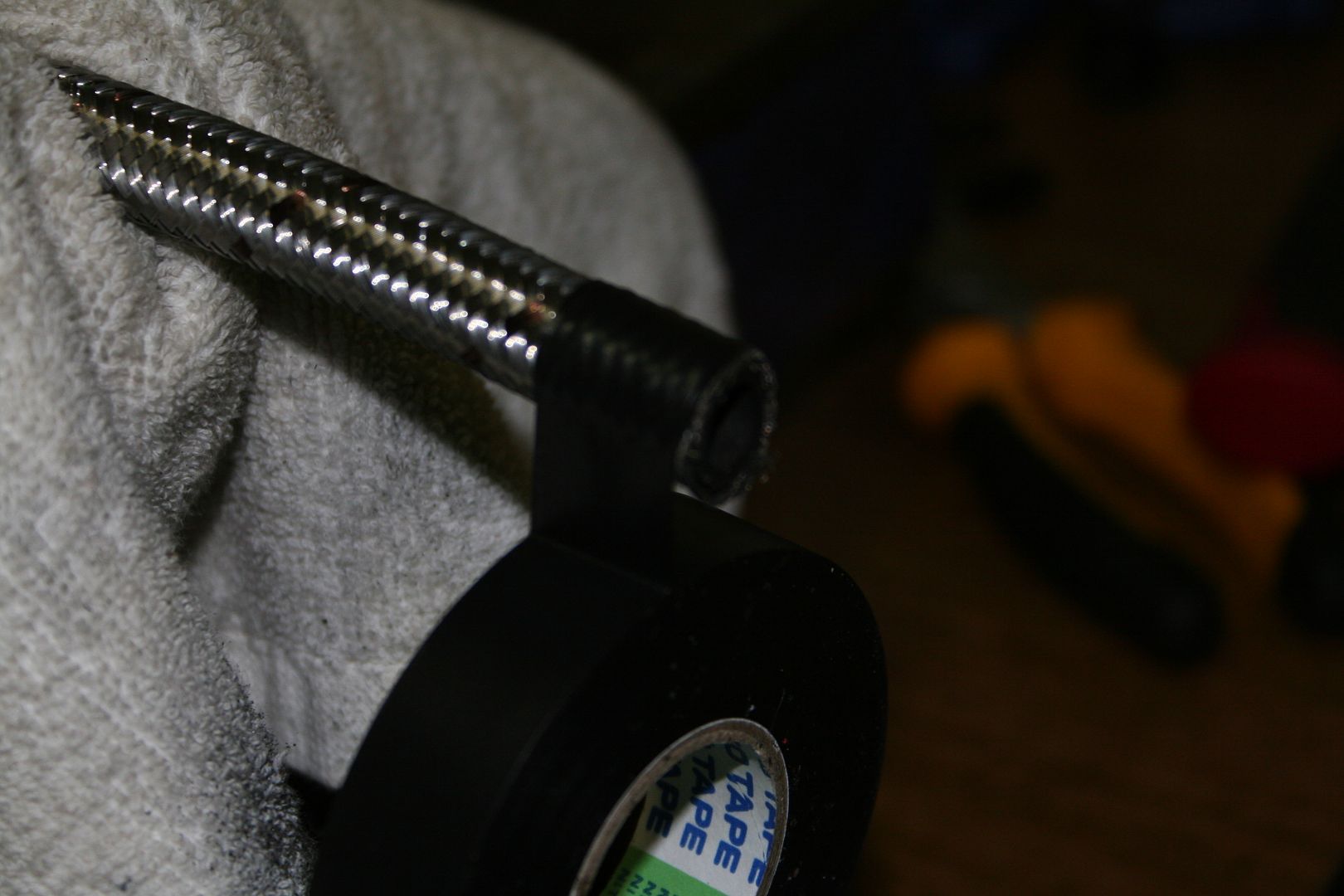
The Earls connectors are made up of two parts the red inner (I call it the inner as it ends up on the inside of the hose if that makes sense) section & the blue outer section
Now of course I cocked up the first cut.. I simply tried to cut right through but as I got to the final bottom section the waste cut off section was flopping around & it pulled some of the steel strands… so for my 2nd attempt I help the grinder in one hand & used a set of pliers to hold the waste section taut as I was cutting & this did the trick. Then I held the inner non movable section of the connector in my vice & slowly press fitted the hose into the connector, being very careful not to allow any stray steel strands to go outside the connector
Once the hose was in the connector far enough, should be just shy of the threads
I then marked the hose so I could see if the hose moved at all out of the connector whilst I screwed in the inner section
Then I applied a little oil to the blue outer connector & placed it in the vice & proceeded to press the red connector onto the threads whilst screwing it on at the same time
Once it was on hand tight I then did it up with a spanner in the vice
I then checked that the hose hadn’t moved from the line I marked earlier & then you’re done.. the first one took me longer than it should of to be honest as I was being very careful not to bugger up the hose or the shiny connector, the rest of the connectors went on in no time
 0
0 -
Once I had mastered the art of hose building I was feeling very chuffed with myself I must say (I know small things, small minds) then I arranged everything out on the bench to ensure that I had enough ends & to be sure I knew where I wanted everything to be in the engine bay

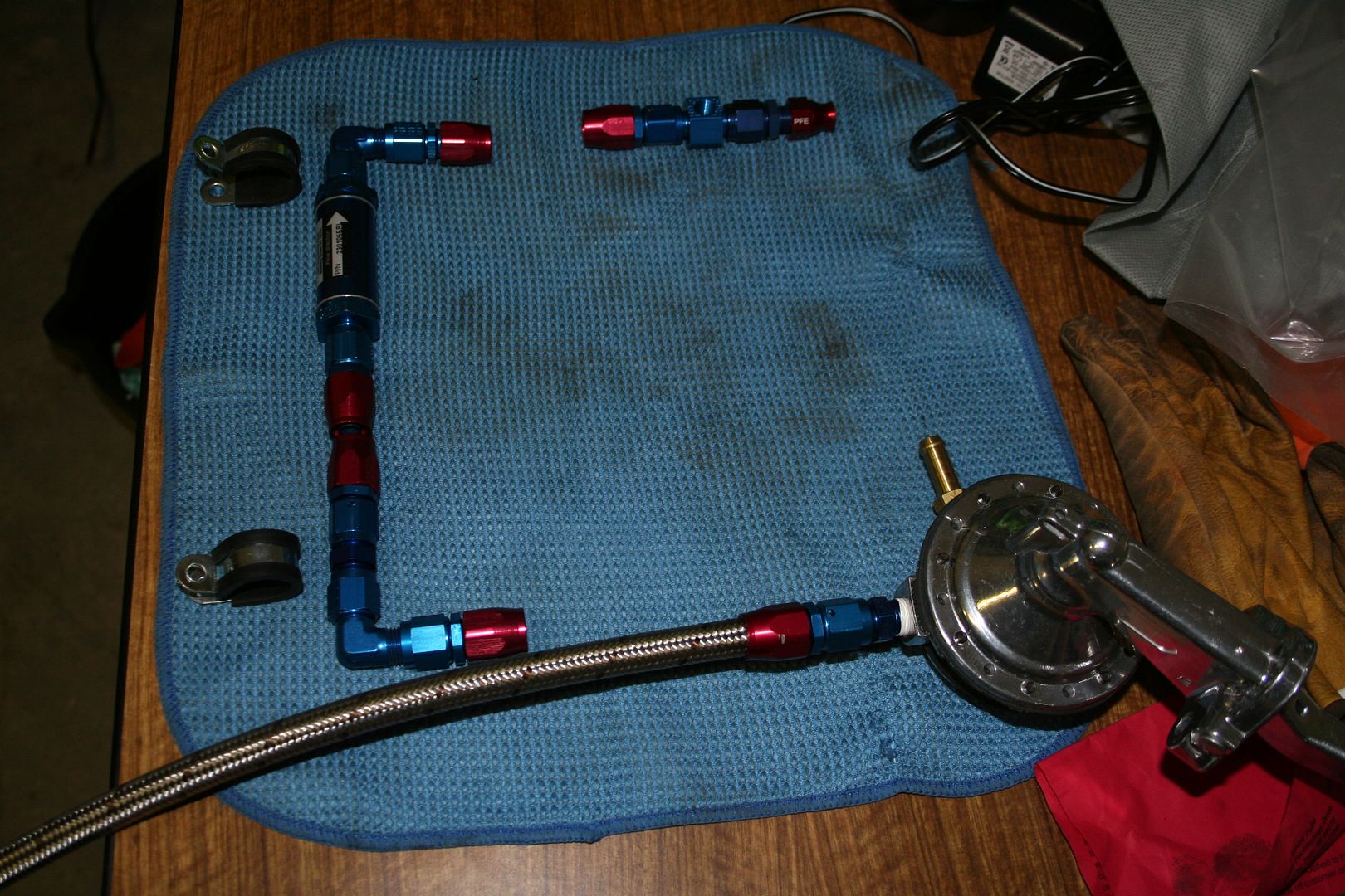
Fitted the new fuel pump & ran a new length of rubber hose from the tank hard line to the fuel pump.. I’m now thinking of running a full length of braided hose from the fuel pump back to the tank… not 100% sure yet, I’m also thinking of fitting an aluminium drop tank to replace the OEM tank & running a proper electric pump at the tank end… we’ll see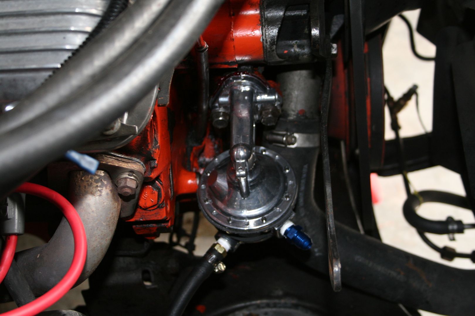
Started to route the new line & filter in, making sure that none of the bends are sharp & that there is nothing for it to catch on or rub against, it is touching the water bottle but I’ll keep an eye on that

The next part of the puzzle was putting an AN adapter piece onto the metal fuel rail from the 6 Pack, you can see the red cover on the end of the rail in the pic above. They do make an adapter than uses an brass olive that forms the liquid tight seal, I had to cut off the existing flared end of the pipe as you can see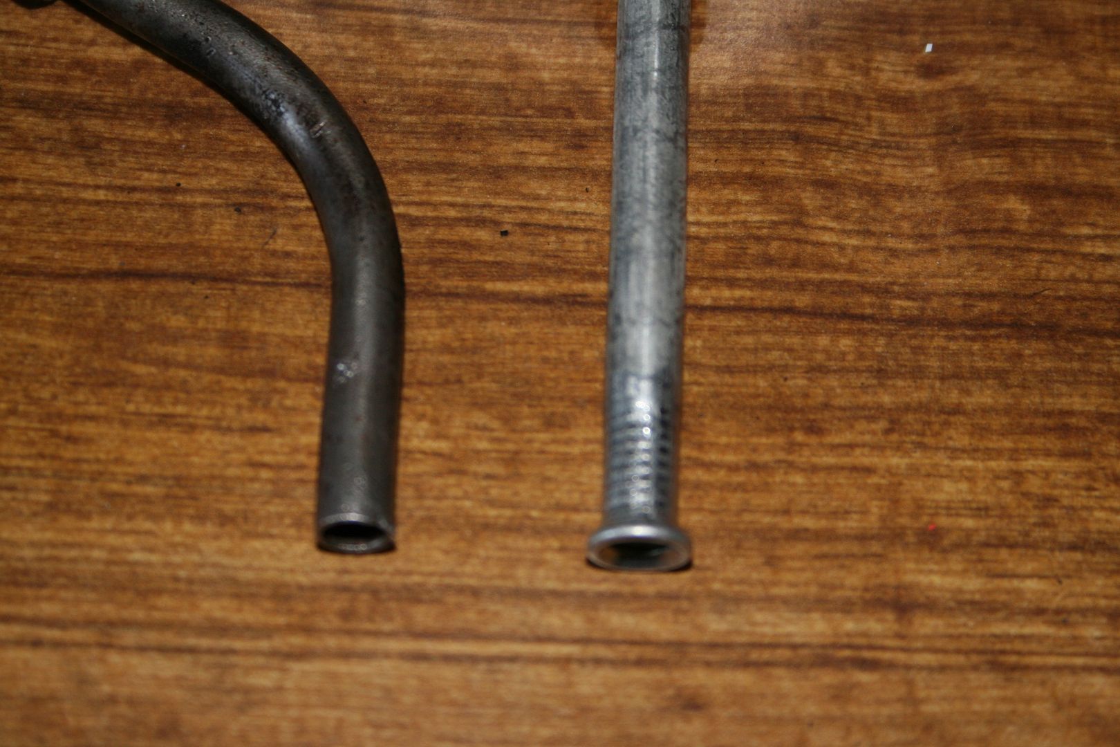

This had to be done so that the red connector end & the olive could both slide onto the fuel rail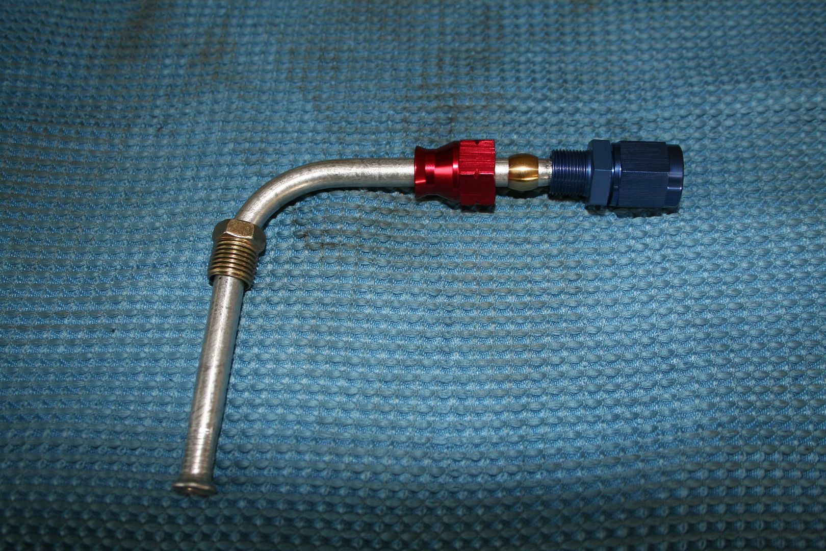
Then you simply push the blue threaded end into the red connector & tighten until they join crushing the olive & making a leak proof seal, sadly I damaged the soft connector in my vice.. note to self but some soft jaws 0
0 -
Then I simply connected up the other sections of hose that I had made up & installed my inline fuel pressure gauge


Now with the alternator reinstalled it’s a very cosy corner of the engine bay, but everything fits & nothing is rubbing or catching so I’m happy 0
0 -
Ok, so I’ve got a long list of things that I want to do/fix on this car & some are near time & other are longer term.. as I know that the car is currently too load to get on the road here in Australia I’ll have to get some mufflers installed, my thinking is that I have these installed in the final section after the diff. I plan on getting some flanges installed so that the section from the diff to the rear hanger can be bolted off easily, to this end I’ve gotten a new set of shiny tips for the exhaust.. so I’ll have two sets of exhaust ends, one with mufflers & one without is my current thinking.

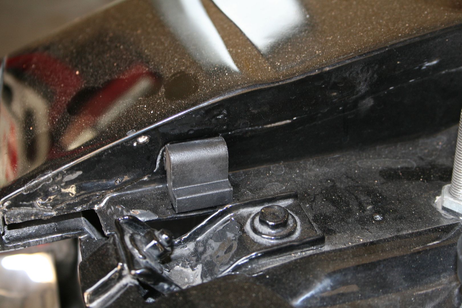
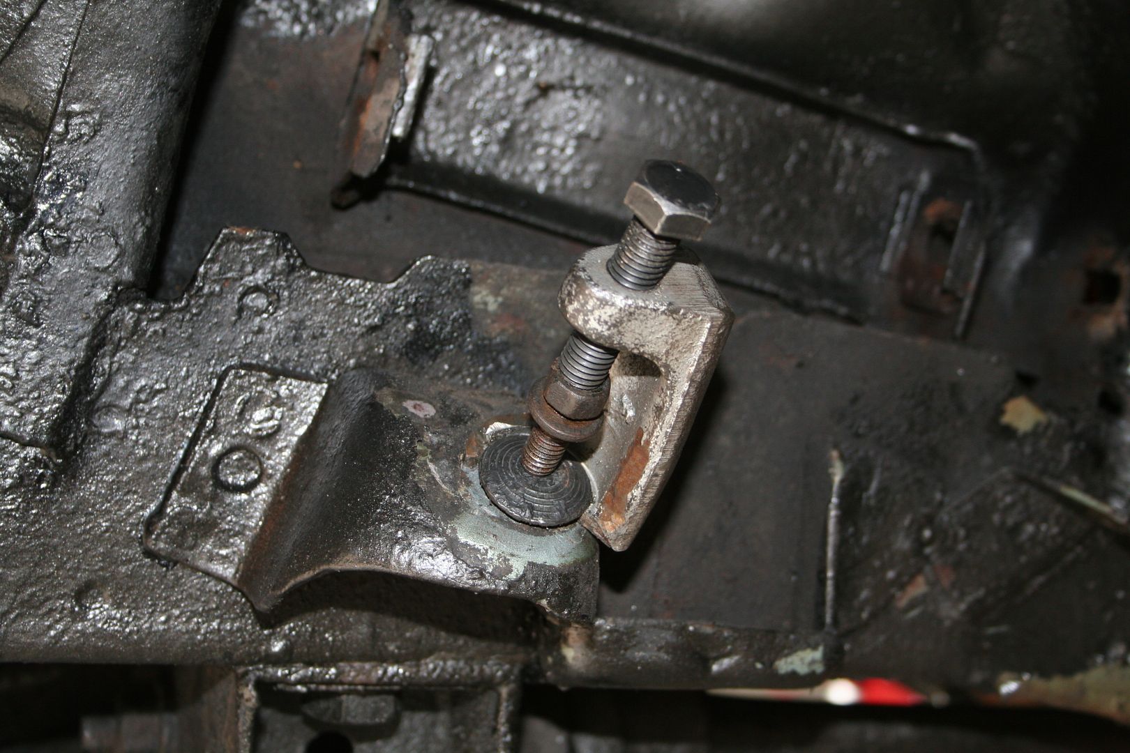
Another thing that has been bugging me since I bought this car is to do with the bonnet, the hinges are shagged, they sag, wobble from side to side & the bonnet moves front to back when your driving also.. so I’ve gotten a new set of hinges to install
I had also noticed that some of the rubber stops that you expect to see along the side of the fender to hold the bonnet in place when it’s closed where either missing or badly perished, so I bought a new set of them
Fitting the front two has a made a huge difference, the bonnet is now snug when it’s closed & it doesn’t move around anymore.. it used to move & rub up against the locking pins & cause a most annoying squeak.. not anymore, job sorted.. a I’ve said before sometimes it’s the little things that make all the difference
On the subject of locking pins, as the bonnet was moving it’s actually bent up a little where the pin protrudes through & I’d never been convinced that the locking pin surrounds where legit, they just looked like crappy disks of 1mm steel screwed onto the bonnet.. so I ordered a new set & what do you know I was right.. once the hinges are fitted, I’ll fit these also
 0
0 -
Now one of my slightly longer term plans is to respray the who car, once I have the car back together & legally on the road I plan to drive her for a few months as I really miss driving her & then once I’ve had my hit on the Mopar 6 pack crack pipe I’ll then look to get the body sorted… sadly the English & Irish climate has not been kind to this old girl.. there are some rust spots showing up just behind the doors, & on the drivers side I think that this is actually the result of a shoddy repair job in the past.. I won’t know until the paint is off but this just screams to me I’ve just 2 inches of bog & chicken wire here to patch up this… so I’ll be ordering some rust repair panels I’m sure to this sorted. The other issue is the vinyl roof that was not fitted correctly, I know it was a DIY job by the last owner & he either didn’t do the prep right or the conditions in his garage didn’t suit the job… but there are more bubbles in this roof than in an aero bar.. I’m not planning on refitting one either, once it’s off I’ll leave it off. Another thing that I plan to do is to change the front & rear valance panels they are shocking.. the rear is a simple one, just buy a new panel & have it installed.. the front I’m going to play with, I’ve bought a set of clear lights from a ’68 Charger to fit in place of the orange ones that she has stock.. now of course they are not even close to being the same size or shape, so I’ll be buying a new front valance & grafting in the correct openings to accept the Charger clear lights
The Cancer bubbles passenger side
The drivers side splitting bog
The vinyl roof… very bubbly

It’s also actually lifting up now around the front windscreen & the wind is starting to peel it back…
These are the ’68 clear Charger lights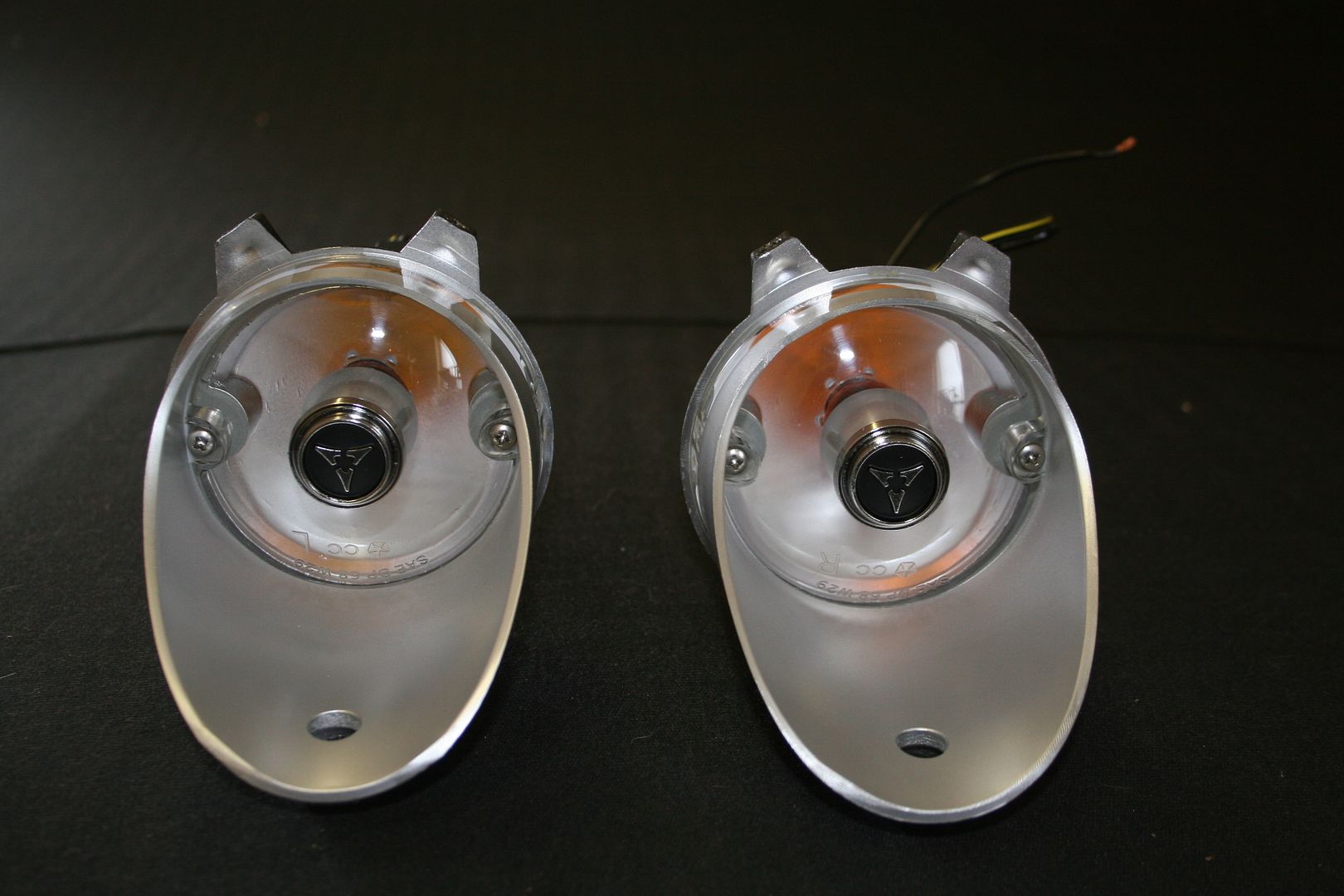 0
0 -
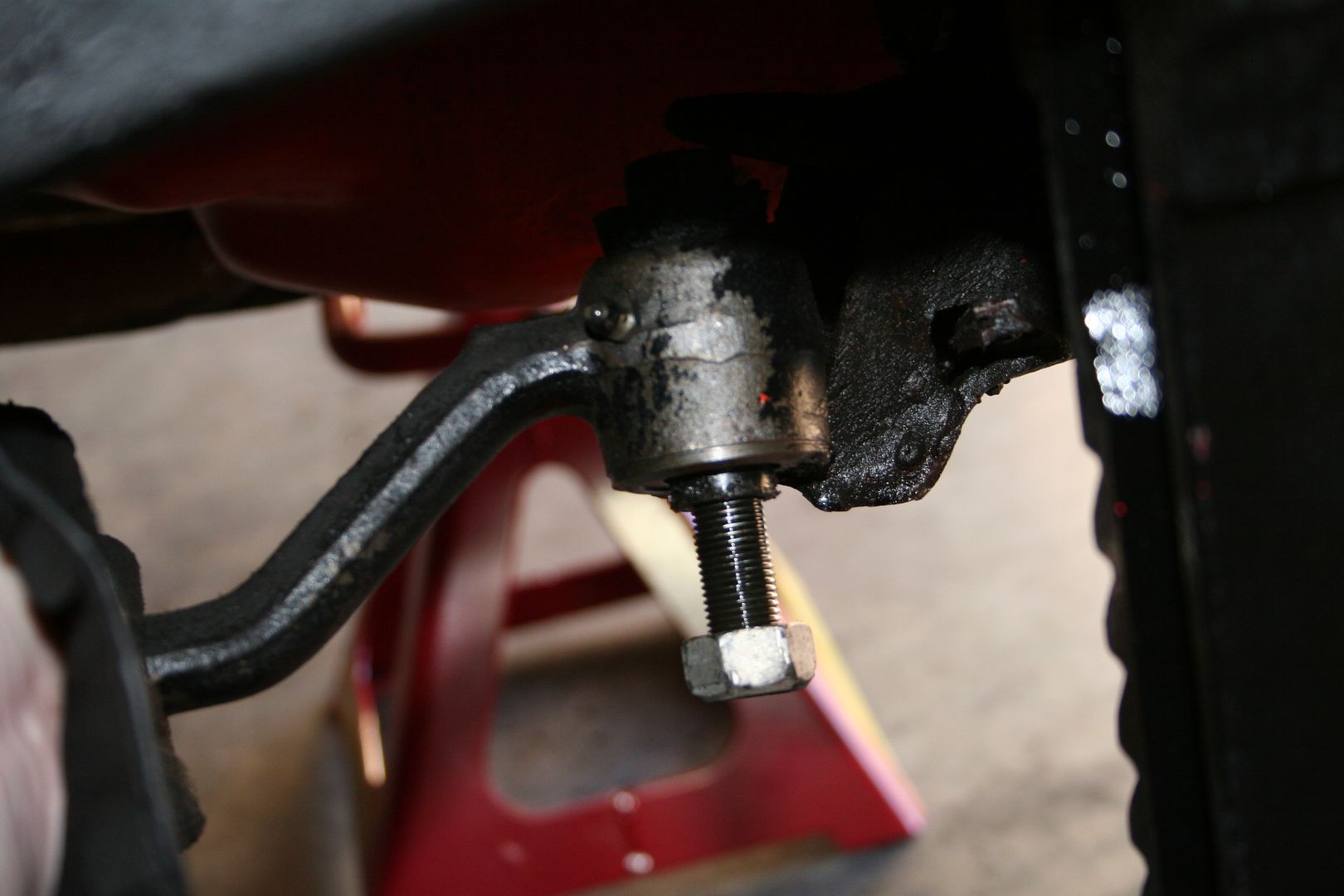
When I was going over the car looking at what my untrained eye could see that needed to be done to get the car on the road here in Australia I noticed that the tie rod ends where buggered & would need to be replaced. I also knew from when I replaced the rear shocks many posts ago now that the rear springs where also shot & really needed to be replaced too. I then started to go over all the suspension bits using my biggest pry bar to see what if any slop or play was in there.. hmmmm… lets just say that most of the rubber bushes & the ball joints where past their prime.
So I had been doing some research on the Interweb about resto-mod Muscle cars & Challengers in particular & I’d been looking at several options open to me other than just replacing the buggered parts with stock parts.. after some late night google research I finally had what I assume alcoholics call a moment of clarity & I settled on the set up that is on the Hotchkis E-Max Challenger (I’ll wait whilst you go google that now).. so I bit the bullet & ordered what they their Total Vehicle System, or TVS package as they seem to call it. The main reason I went with this kit over the others on offer was because I didn’t have to replace the while K-Frame to install this kit & there seemed to be many more positive reviews around this exact kit & Hotchkis in general on the web than the others out there.
The kit came with the following:
Geometry corrected tubular upper control arms
Adjustable Strut Rods
Adjustable Steering Rods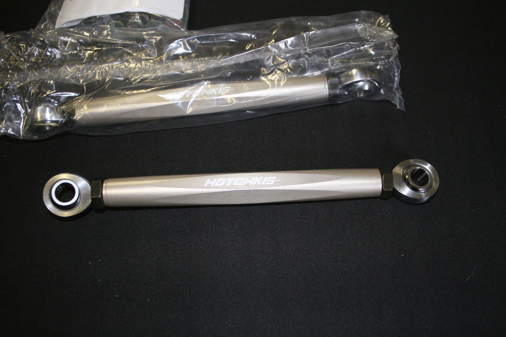
1 ¼” Tubular front sway bar (rear bar in the pic) & a 13/16” Tubular rear sway bar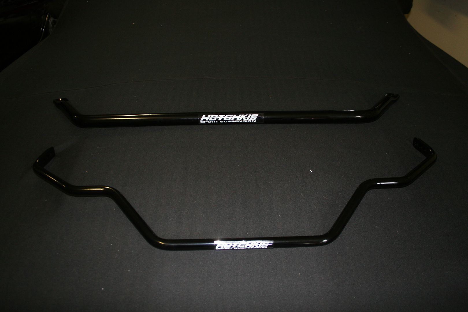
Geometry Corrected rear leaf springs
A set of Chassis Sub Frame connectors to join the front & rear frames together
Also with the kit was all the hardware, so U-Bolts, brackets all nuts & bolts needed etc
Stay tuned for a step by step guide to tearing down the old suspension, the clean up as needed of the parts that will be re-used (this is as far as I am to date) & then ultimately the build up as I install all of these new shiny bits back on the car… as soon as I can find someone who can weld, as the rear sway bar brackets & the Sub Frame connectors need to be welded on & that is definitely outside of my comfort zone so as much as I want to do all this myself, I will be outsourcing that piece to someone who knows what they are doing.0 -
Next came the strip down of the original suspension from the front of the Challenger so that I can bolt up all my shiny new Hotchkis bits that have been sitting around the garage taunting me the last few weeks. I wasn’t thinking that any of this would be a major difficult job, it would just be time consuming.. I have a rattle gun for undoing stubborn nuts & bolts, I had a couple of different ball joint breaking tools, 6 axle stands & 2 trolley jacks.. so I figured I had all the bases covered.
I got the old girl nice & high in the air & onto the stands to allow me to work under her, I swear when I finally buy a house here I’m getting a hoist, they are definitely the must have toy now for the home garage. I soaked every nut & bolt that I would be removing with lots & lots of penetrating fluid to hopefully ease the removal as some of the parts looked like they had not been off the car since 1972…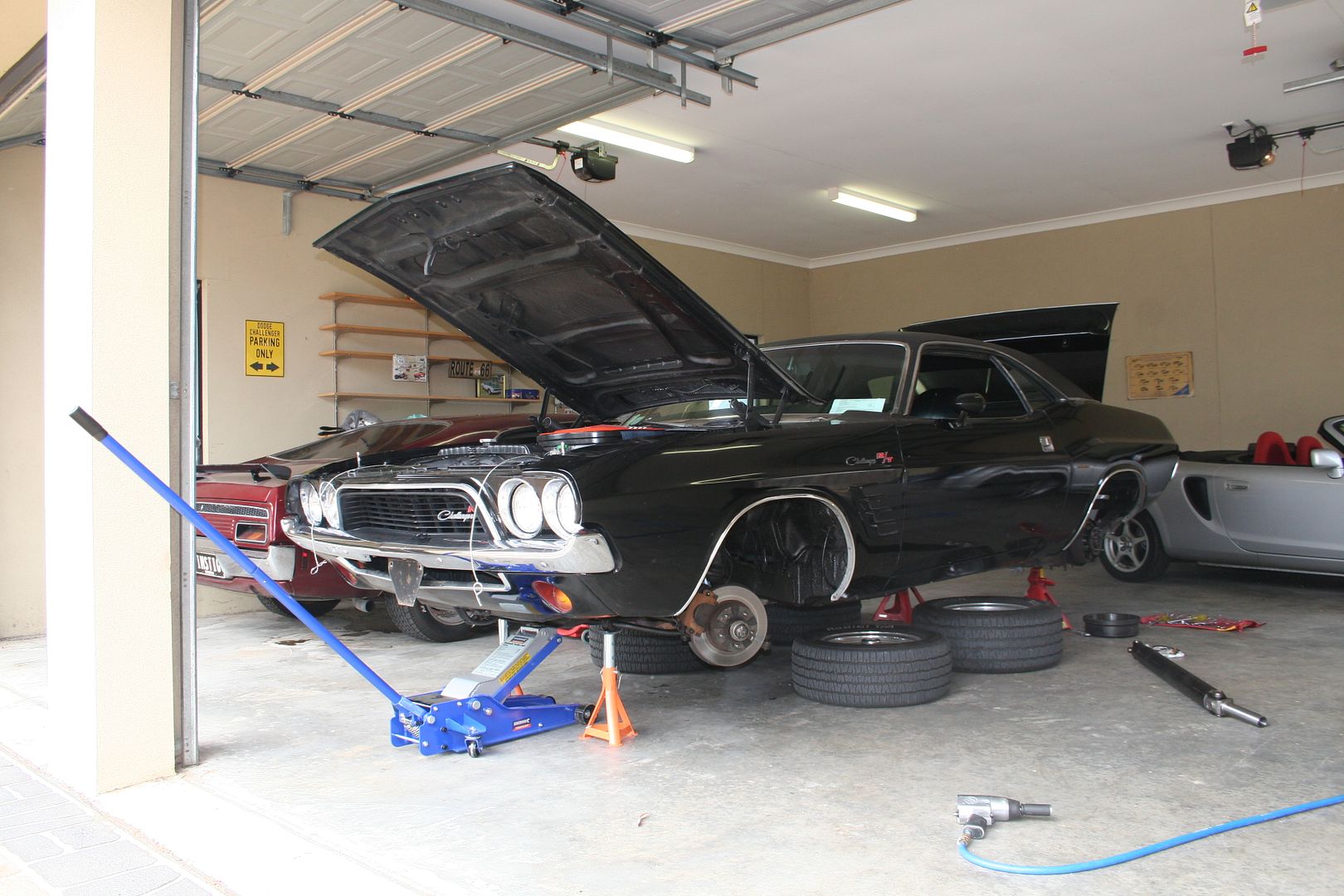
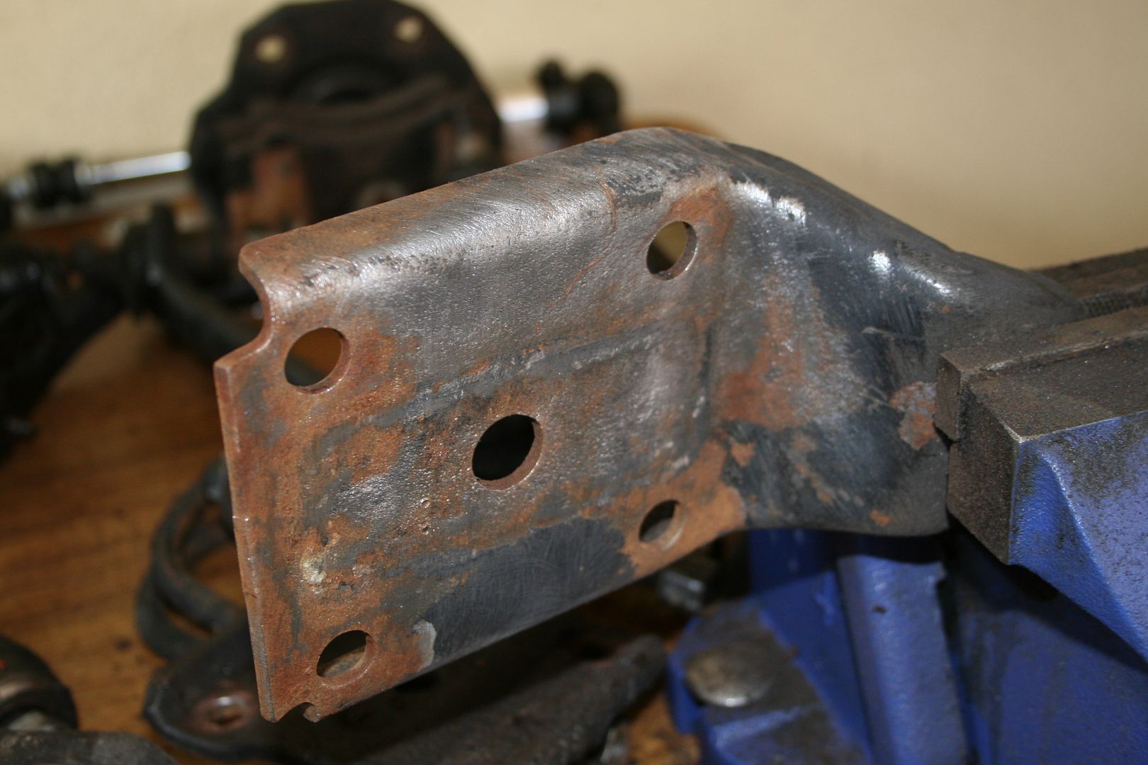
Now the last owner had done a great job of coating the underside of the car with vast quantities Schultz for rust protection & whilst I’m very grateful of that from a rust prevention point of view whilst the old girl was living in Ireland.. man it caused me no end of issues with regards to getting the nuts & bolts off the car.. you can see in the pic below how the threads are all gunked up with this ****.. now the issue this caused was that the nuts didn’t want to come off at all, so when I had to use the rattle gun to remove them the resultant friction heat invariably stripped the threads either off the bolt or from inside the nut.. so my advice for anyone thinking of spraying sound deadener or rust protector under you car take the extra bit of prep time & tape over all the suspension nuts & bolts so you don’t end up with this issue later on down the track. Luckily I had all new nuts & bolts as part of my kit & I had planned on not reusing any of the old stuff as it was all rendered useless once it was free of the car.
So basically all the parts you see hanging off the car here need to be removed
The first piece I tackled was the tie rods, I removed the split pins & rattled off the nuts then I attached the joints with my breaker tool
Then I lay the old piece next to the new to measure up the length so I can get it at least close as it’s going back together, obviously a full alignment will be needed at the end of all this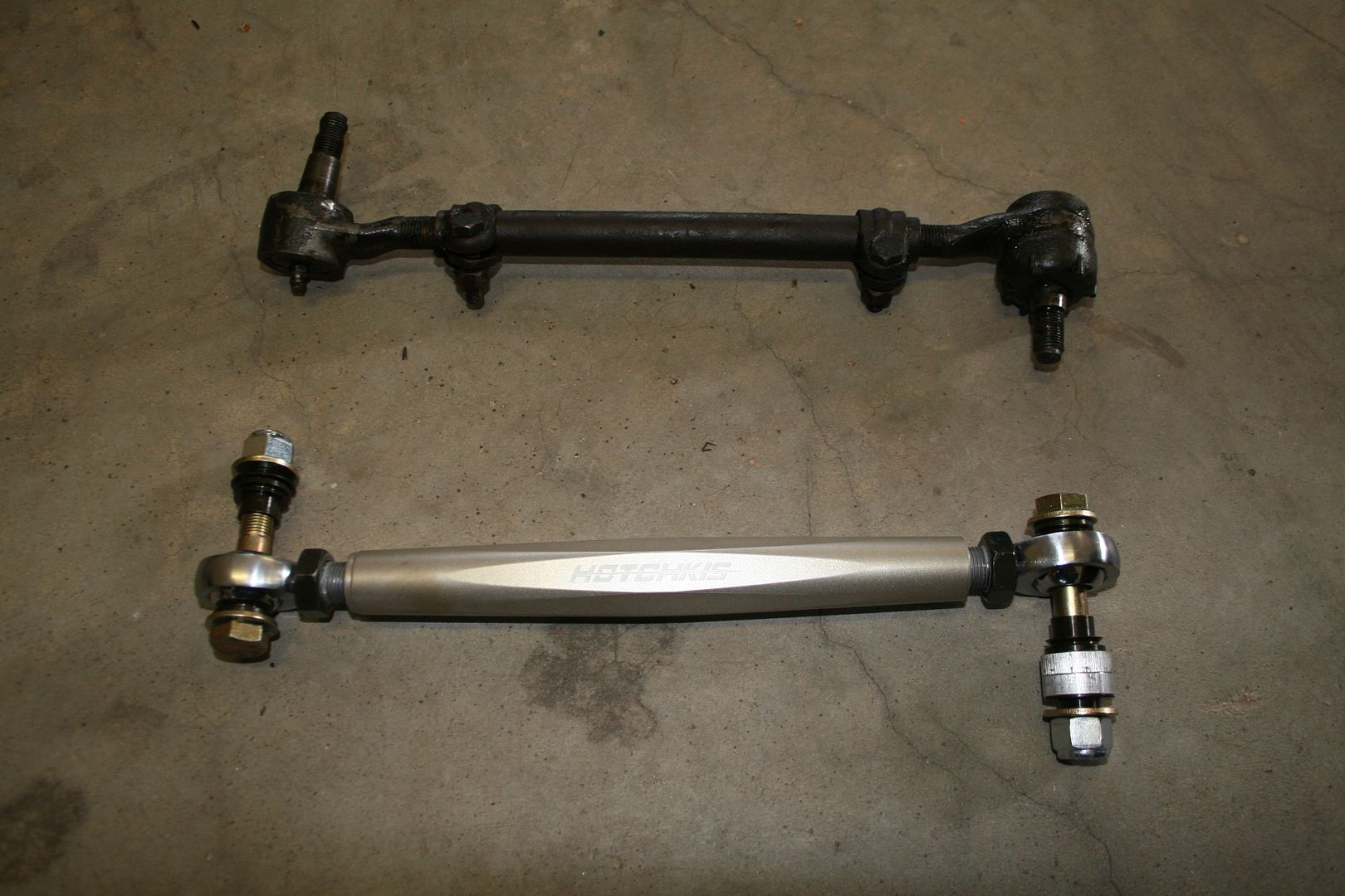
After both of them where off I decided to remove the old front sway bar first, this couldn’t be simpler really, undo the bolt that holds the bar to the mounting bracket on both sides
Then unbolt the bracket from the body, the TVS kit comes with both the bracket that holds the rubber & a new bracket to bolt to the K-Frame also

Old vs new, according to the info with the kit the new bar is 220% stiffer than the old one was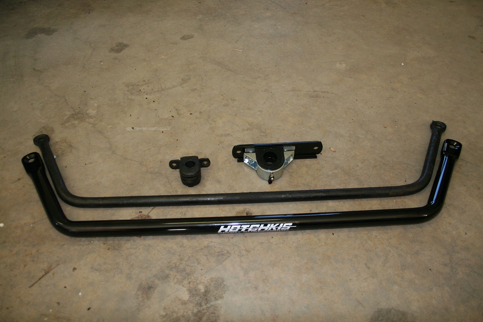
I then replaced the K-Frame bracket with the new one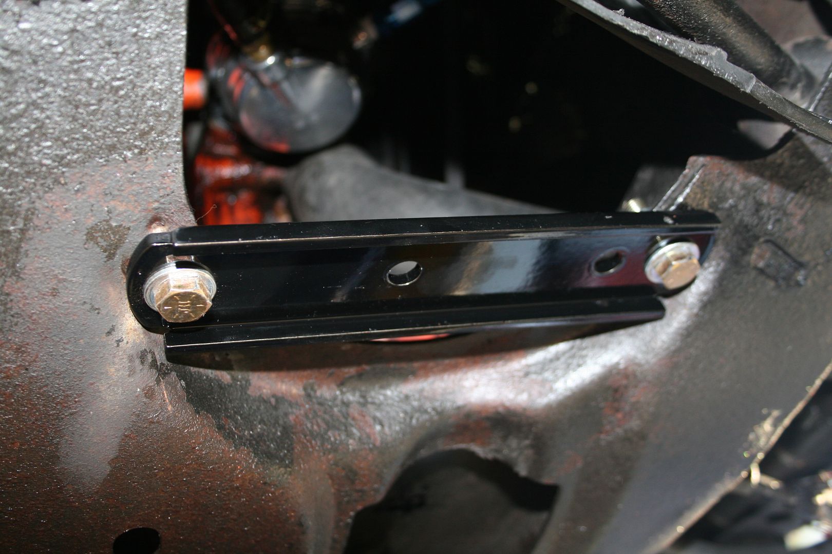 0
0 -
Next I removed the brake callipers from each side & removed each of the shock absorbers carefully as I will be reusing these as they are practically new adjustable ones

Then I didn’t have a breaker tool large enough to go over the top ball joint & clamp down on it so I had to use my fork to wedge between the joints to break them.. now on the drivers side I just belted the crap out of the joint until it finally gave way with a very load bang, but on the passenger side I had a moment of clarity & I realised that if I jacked up the whole assembly until it was level, knocked the fork in until there was some tension on the join & then dropped the jack quickly the joint split with little to no fuss.. I’m sure most people knew that trick but I didn’t..

& then I used my Formula 1 inspired home made brake fluid catch can to drain all the fluid out of the system so that I remove the brake lines & put them on the bench out of harms way, I’m currently in talks with Red Bull & Ferrari about selling the rights to this tool
Then I simply undid the nuts holding the brake spindle onto the lower arm & slide the whole brake spindle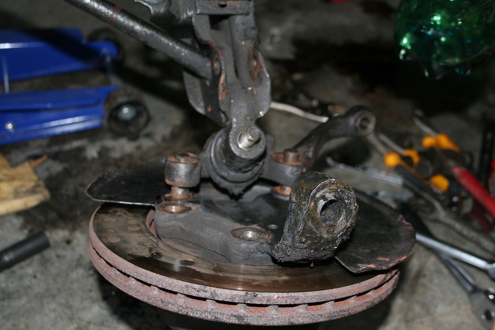

Next to be removed was the lower ball joints, now these are not part of the Hotchkis TVS kit that I had ordered, but it was about this moment that I had another moment of clarity & realised there was no point in doing a half arsed job here, so I decided that I would buy any & all parts that were not in the TVS kit new as well & replace everything… this sadly will mean that I would have to wait for more parts.. but it would be worth the wait. Luckily the ball joint cracking tool that I have did fit these bottom joints so getting them off didn’t need the use of a hammer at all.. happy days

Then I undid the cammed bolts that hold the upper control arms in place, I forgot to take pics, but you need to remember what position the bolts where in when you removed them as they are adjustable & you want to put them back as close to the way they came out.. I have ordered all new cammed bolts to replace the old ones I removed.
New upper arm vs old 0
0 -
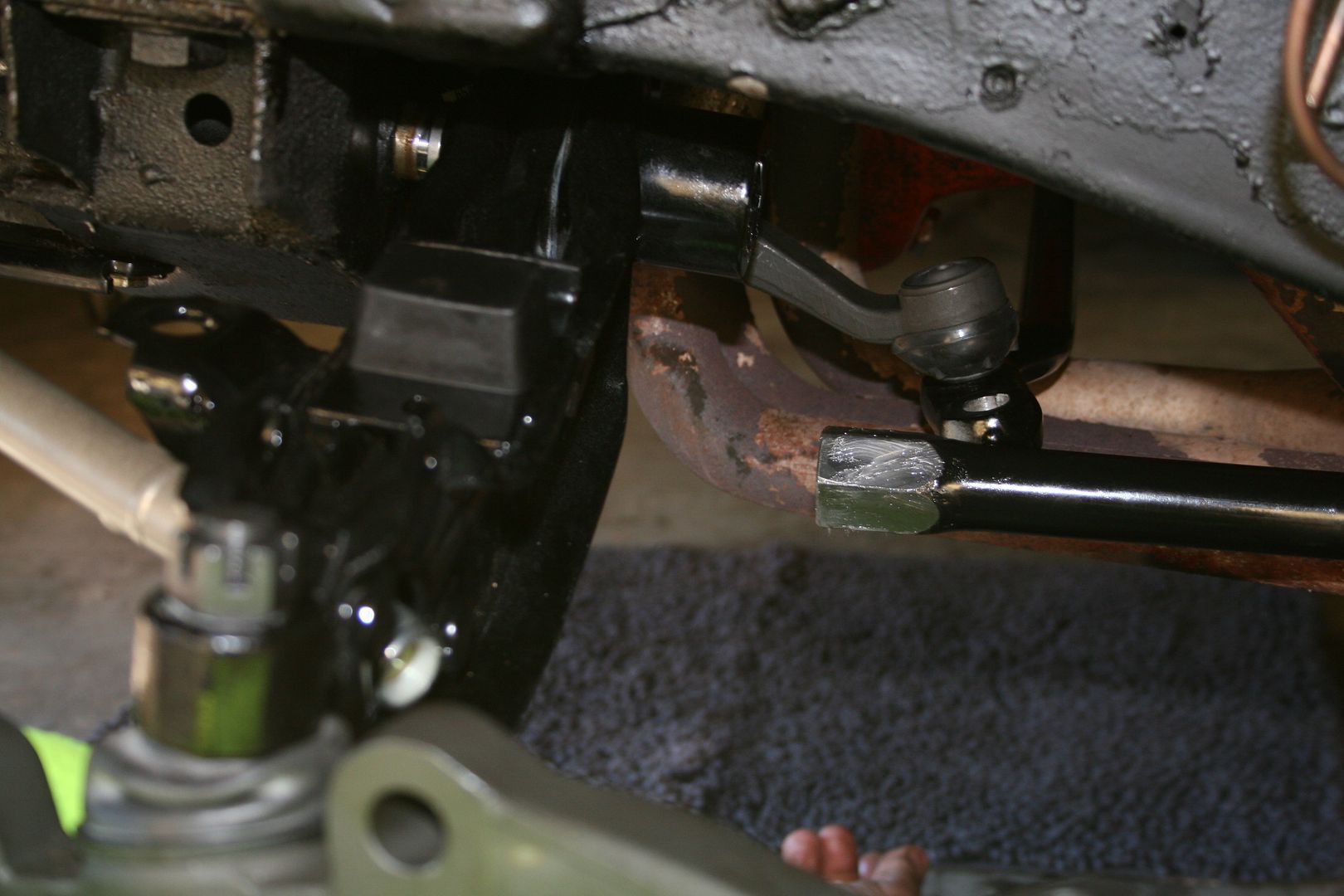
Next to be removed where the strut rods, that’s the road that you see here going from the lower control arm up to the chassis rail
I’d already used the rattle gun to remove the retaining bolts earlier, due to the fixed length design of these bars they don’t come out one you’ve simply undone the nuts
Now I hoped that once the lower arm had dropped down as low as it would go that the struts would be able to slide out due to the extra travel…. Sadly that’s not the case at all, so off I went to look it up in my new manual & then I was slightly bummed to discover that the only way to get them out is to remove the whole lower arm off the car.. & the only way to remove the lower control arm is to remove the torsion bars that run through the frame.. so a quick read up on how to do that & it seems you need a special tool, the guide specifically says not to clamp the bars with a vice grips to get them out as that will damage the bars & since I plan on reusing them I opted to get the special tool.. if you had access to some scrap steel & you knew how to weld you could make one of these in minutes I guess. It simply clamps onto the bar & then you hit the tool with a big hammer & out pops the bar..
In order to remove the bar there is a clip that live at the rear of the bar that holds it in place in the frame, I had to spend a while cleaning out ****loads of that bloody Shultz crap from here to let me get the clip out so that I could remove the bars, again something that anyone shultzing a car might want to cover up. Once the clip is off just hit the tool with a hammer until the bar starts to slide rear woods, the hex part that is locked into the lower control arm is fairly short so it doesn’t take much to get it out
This is the rear end easing out now where the clip had been caked in Shultz
Sliding the bar out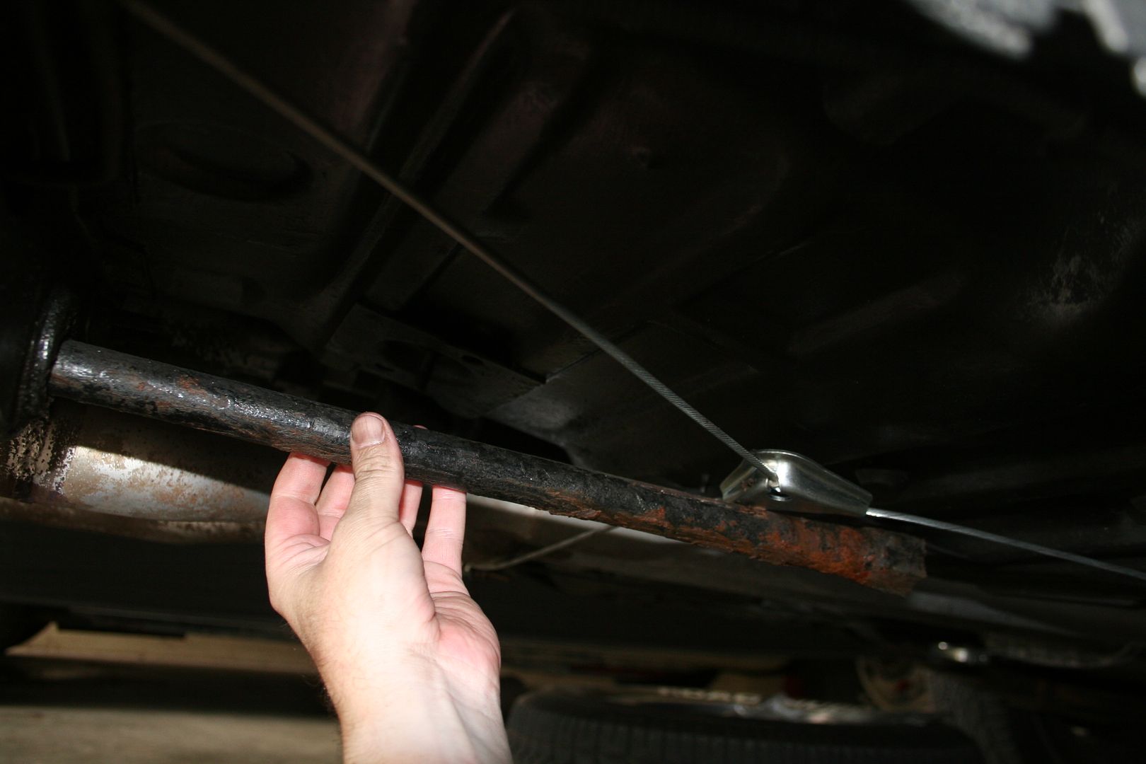
Bar out, these are not interchangeable left to right according to dodge, so I’ve marked them.. I’ll be cleaning them for reuse, the TVS kit did not come with new torsion bars although Hotchkis are sending me a set anyway but I don’t know if I’ll ever get around to using them as they are indexed differently to the stock ones & they reduce the ride height by quite a bit I’m told
Then I simply undid the nut on the lower control arm pivot shaft & removed the whole assembly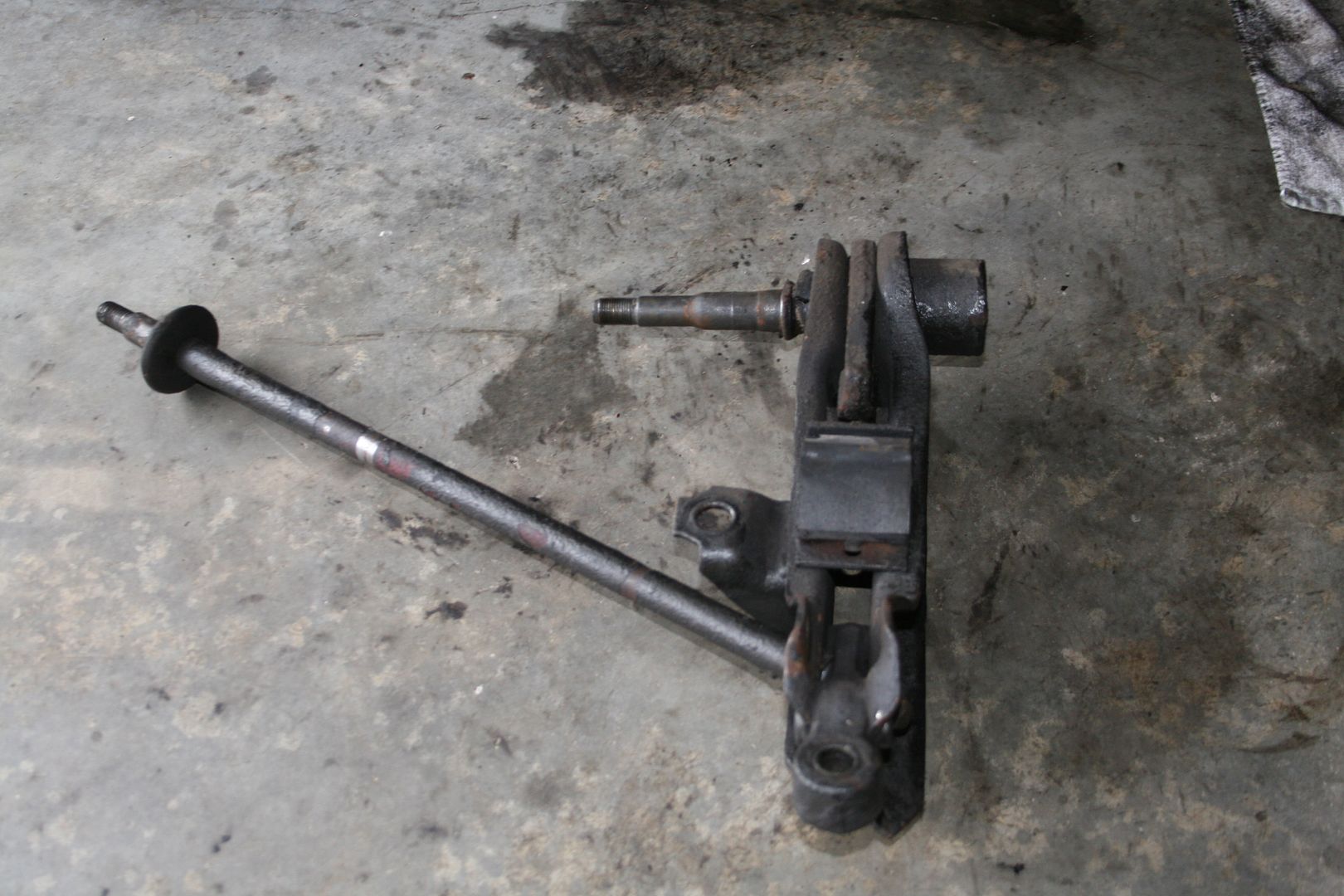
Then the strut rod just slides out
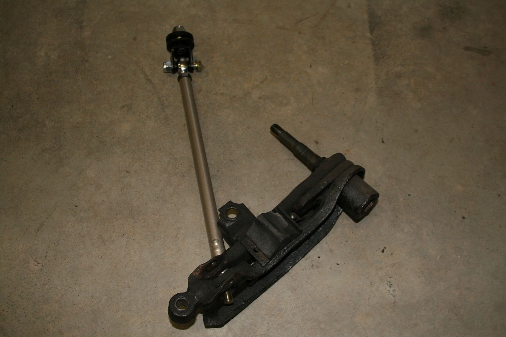
New vs old, the new one is adjustable for length 0
0 -
Advertisement
-
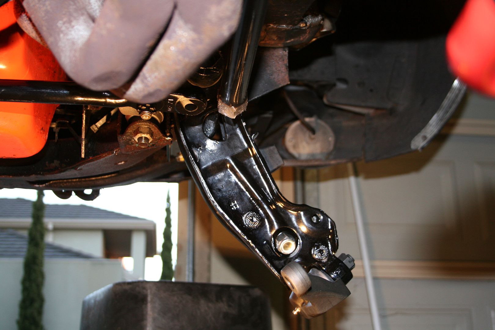
When I test fitted the new one in the lower control arm it became very clear that whilst I have the arm off I really do need to sand blast it & paint it… no point putting crappy looking parts back on & this is a part that is getting reused
The old parts pile was building up now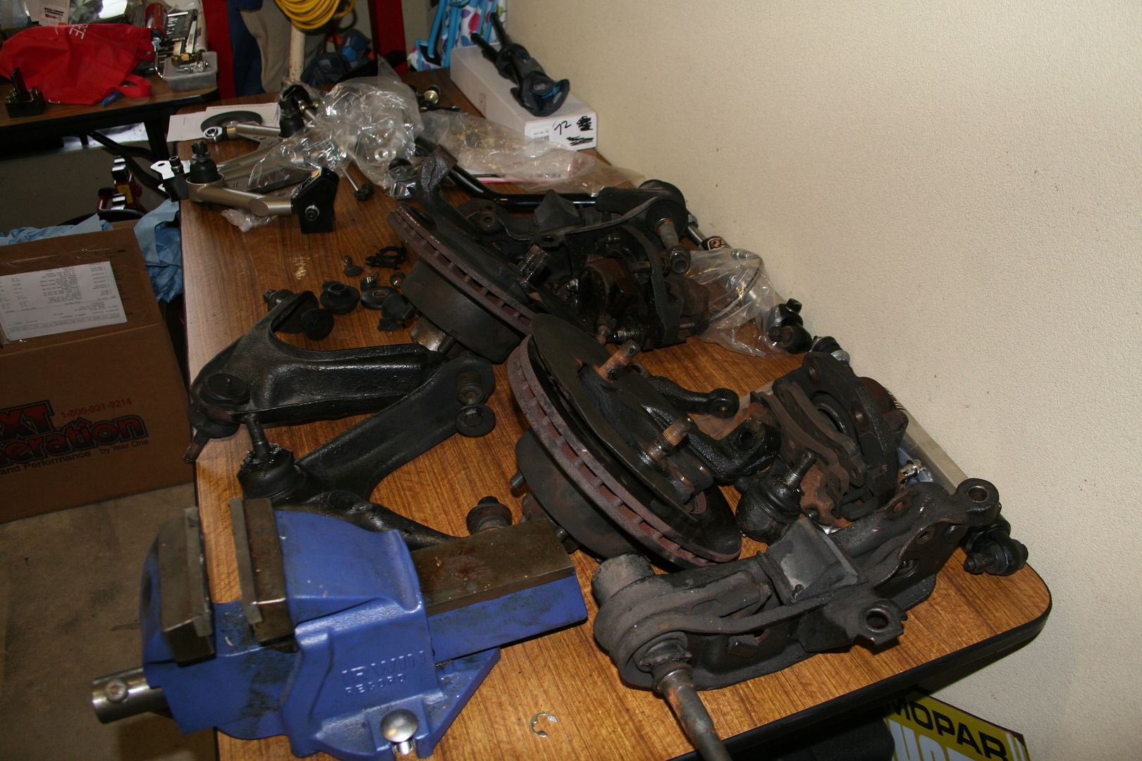
As I was inspecting the lower arms I noticed that the rubbers for the pivot shafts where very very stuffed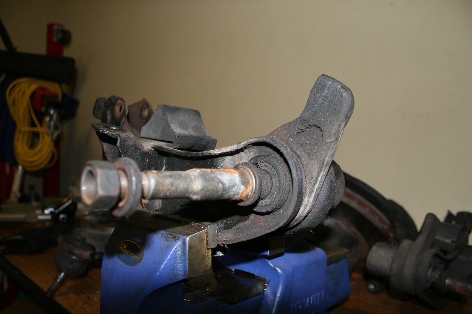
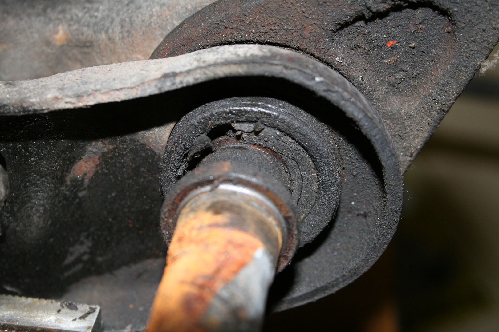

So off to the interweb & a new set of shafts & bushings where ordered.. now I had to press the old shafts out… but I don’t own a press & my normal backup plan of using the vice wasn’t an option as the vice wouldn’t open up far enough.. so I figured since I was replacing them any way I’d cut them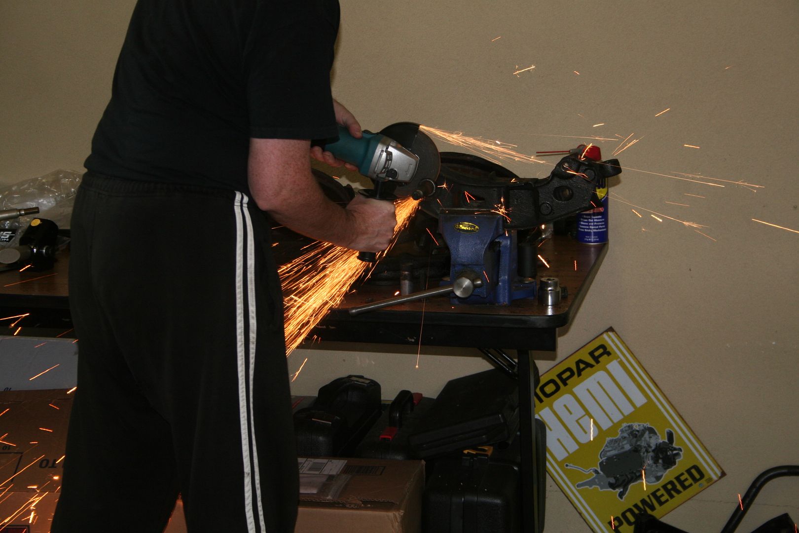

Now the assembly was small enough that I could use two sockets & my vice to press out the shaft, the rubber was fecked
Then passenger side one didn’t need pressing at all… I didn’t notice until I’d cut it, but the rubber was so far gone on this one that the shaft was rubbing on the bushing
This one I was able to just pull out by hand using a pliers.. something I’m sure your not supposed to be able to do, you can clearly see the wear marks 1
1 -
The kit comes with all new bump stops for the suspension, which is a good thing as all the ones on the car are smashed & hard now… sadly due to the heavy coating of Shultz I was really struggling to get the bloody things off as they would just spin when I tried to undo them.. so I invented another tool using an old broken tie rod breaker tool & an old bolt… this is why you should never throw stuff out.. I’m gona make a fortune launching my own brand of special tools
The front is now clear of all the suspension parts 0
0 -
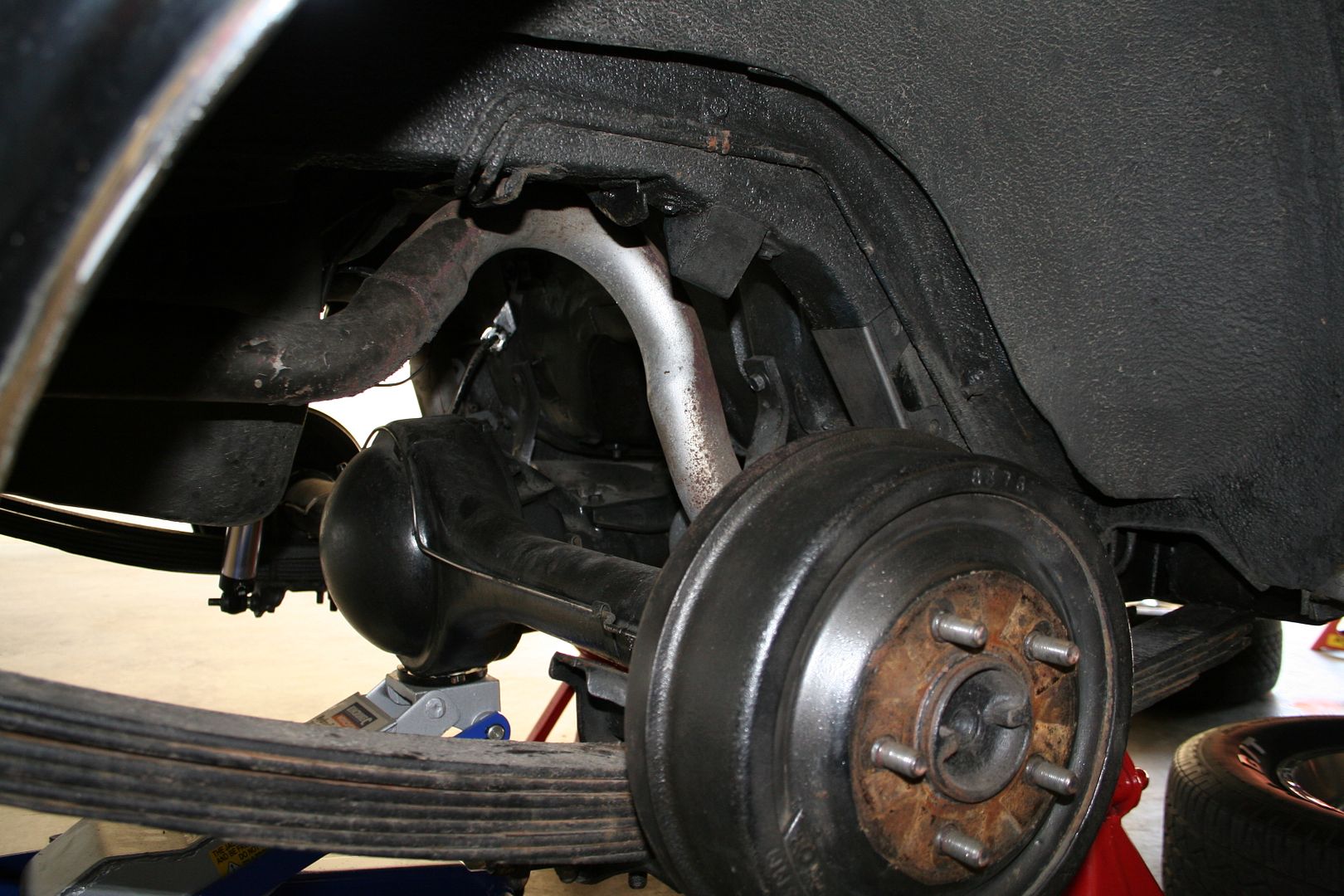
Now that the front end was bare it was time to remove all the hanging parts from the rear end, seemed simple enough.. so I started with the rear sway bar, first I removed the link ends from where they attached to both the sway bar & to the bracket on the diff.

It’s interesting to note, or at least it was interesting for me that he new Hotchkis rear sway bar differs in a few way to the stock one & not just in thickness as you would imagine… the stock bar uses the normal links that you would expect to see on the ends of a sway bat, yet the new bar uses a solid dog bone instead
One of the things I really like about this TVS kit is that every part has a grease nipple built in.. I must now invest in a grease gun for my air compressor & get into the habit of re-greasing this stuff a few times a year. The other big difference is actually how the sway bars run on the car.. the stock bar’s end links are attached to the diff plate where the springs mount & then the bar runs above the diff & has two pivot mounts attached to the chassis rails as you can see in the pic below
Now the new bar mounts completely differently, it’s pivot mounts are attached to the underside of the diff using a set of U-Bolts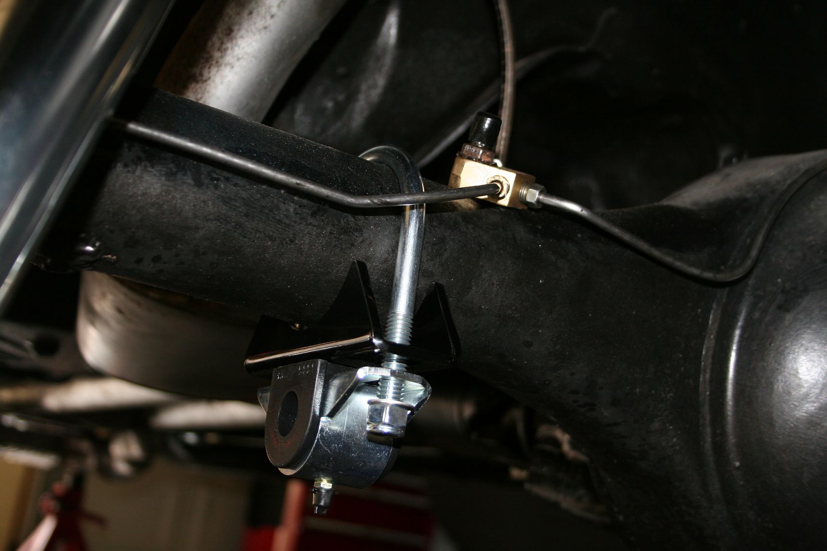
Then the bar runs under the diff, not above as per the original & the dog bone ends attach to new brackets that will have to be welded to the chassis rail, these are in almost the exact same spot as the pivot mounts for the old bar where
Once I unbolted the pivot mounts from the chassis rails it became apparent that there was no way that the bar would be able to squeeze past the frame & the exhaust to be extracted from under the car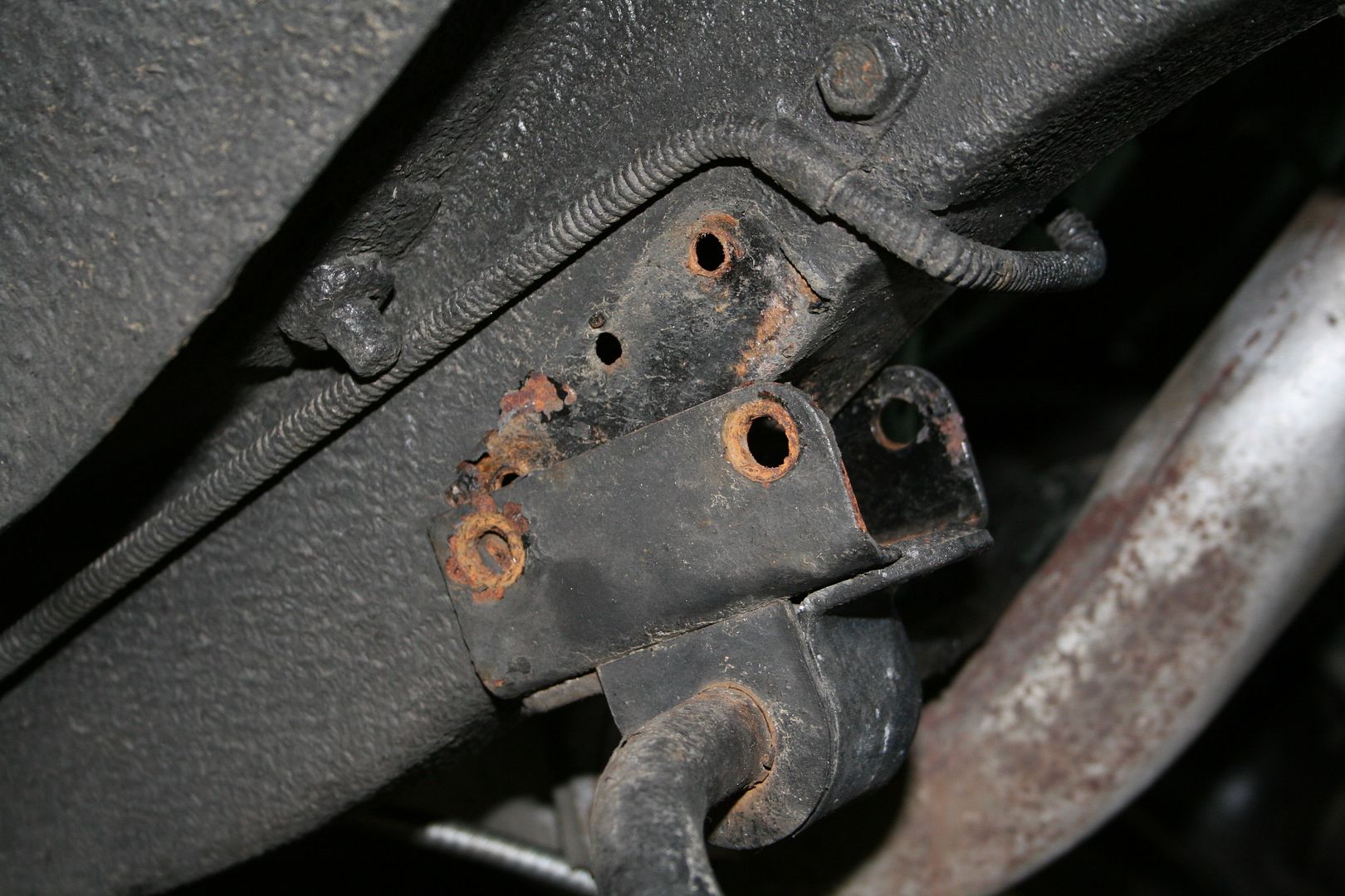
I thought long & hard about removing the exhaust as I’m sure that that is what you are supposed to do, but then I decided that I really wasn’t arse doing that, so I spent more time than I should trying to wiggle the bloody thing out of a gap that I could clearly see it was not going to fit through… then I decided for a more forceful way forward (& no I’m not about to cut the shock)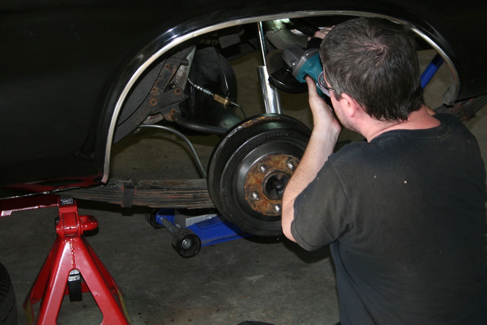
Once I’d cut the weld where the two brackets joined then I was able to pry them open & remove the whole thing off the bar
Now I was able to wiggle the bar out… success, it even looks like I could reuse that bracket if I ever needed to
Old vs new… the old bar as it lays here is as it was orientated under the car pivots at the front & links at the rear , the new bar is upside down.. the new bar will have the dog bones at the front & the pivots not shown here will be either side of the Hotchkis sticker on the bar connected to the diff as show above in an earlier pic 0
0 -
Next step was to remove the brake lines & the shocks from the diff, then pull the driveshaft again & I opted to disconnect the handbrake cables from the middle joins under the car, so you’ll see them dangling from the diff later.. seemed smarted that taking the rear brakes apart again, I also took the weight of the diff off the springs with my trolley jack
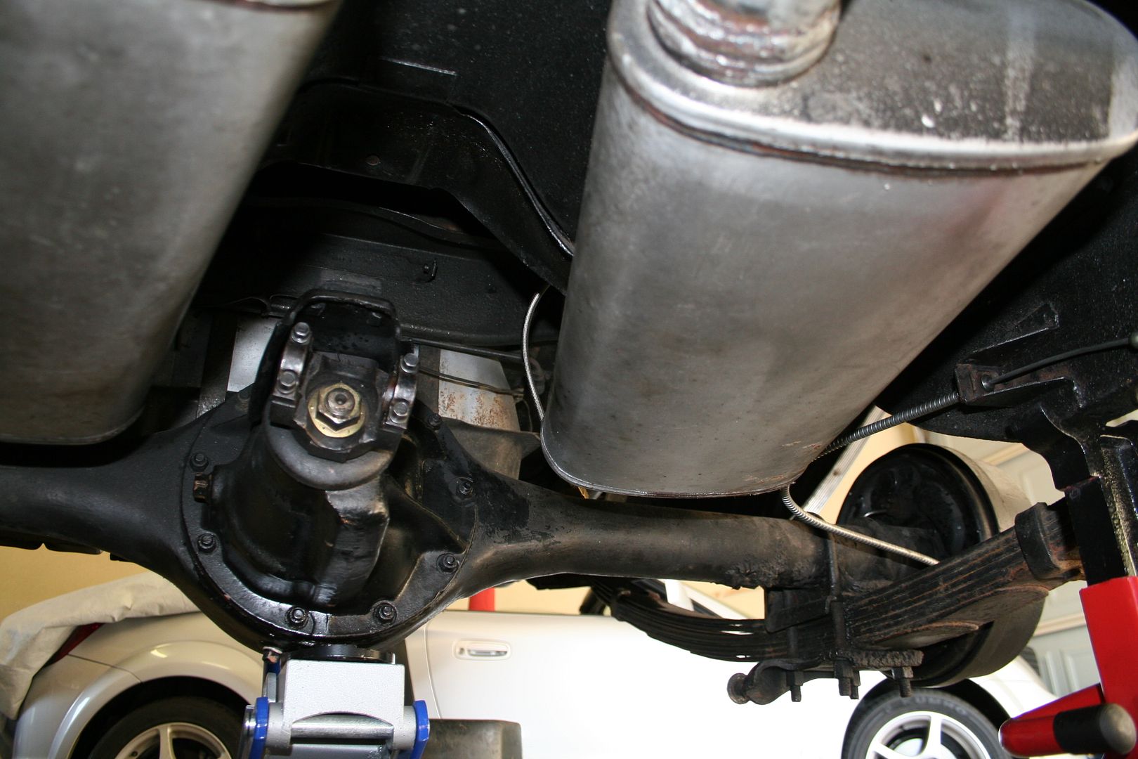
I had planned in my mind to remove the rear bolts from the shackles that hold the springs on & then gently lower the whole diff & spring assembly to the floor & then undo the front bolts & drop the whole thing out so that I could work on removing the springs out from under the car… however I discovered that with the location of the rear shackles & the angle of rear valance panel you have to drop the springs from the front first or they will hit the valance panel… & mine is in bad enough shape as it is..
Next plan then was to remove springs from the car one at a time whilst leaving the diff suspended in mid air, then when they were both out I would gently lower the diff down. So the next step was to remove the nuts from the U-Bolts that hold the springs on, even after days of repeated soaking of these with penetrating oil it was bloody hard to get these undone.. even using an air gun.. again the thick coating of Shultz did not help.. these nuts ate the threads off themselves & the U-Bolts on the way off.. good thing the kit came with new ones, no way these could be reused again.. once all four where off I just used my pry bar to get the bottom bracket off
Once the U-Bolts where off the spring dropped as the weight of the diff was on the jack now
Then I undid the both that holds the front of the spring in it’s bracket… & discovered that the bolt was longer that the gap between the spring & the side of the car!!
Bugger.. onto plan C now, I undid the four bolts that hold the bracket that the spring bolts to at the front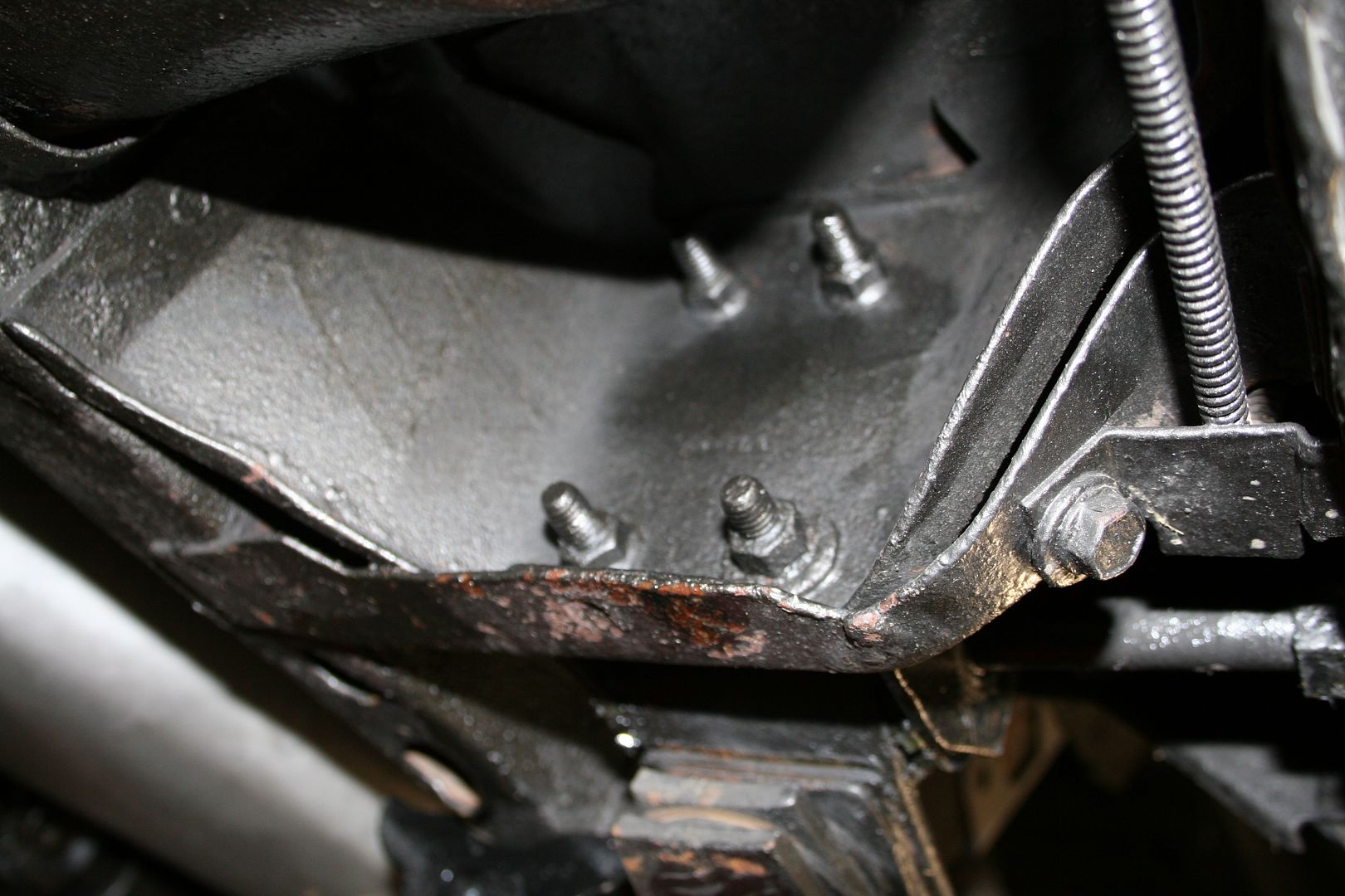
Then I lowered the front of the spring down to the ground
Now I could finally undo the rear shackles & remove the spring sliding it forwards on the ground until the spring was far enough forward to be removed without hitting the valance panel 0
0 -
Old spring vs new spring… the new spring has a lot less leaves that the old stock spring, I assume that will lower the rear of the car some what

Simply repeated what the same procedure on the other side now & then making sure to support the front of the diff housing as the nose is long & heavy I gently lowered the diff to the ground & slid it out of the way
Now the job of removing bits is finally done.. happy days

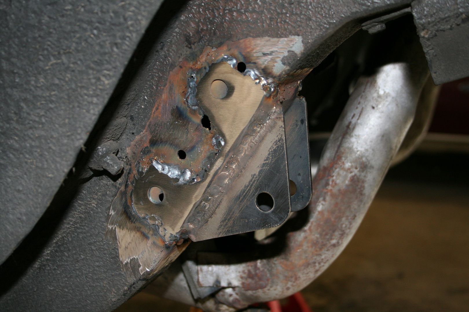
Today I spent some time in the garage cleaning up the areas that will require new brackets to be welded to the car.. So I started cleaning up where the bracket for the dog bone connectors for the rear sway bar will go

Then I cleaned up where the painted bracket will need to be welded to the steel one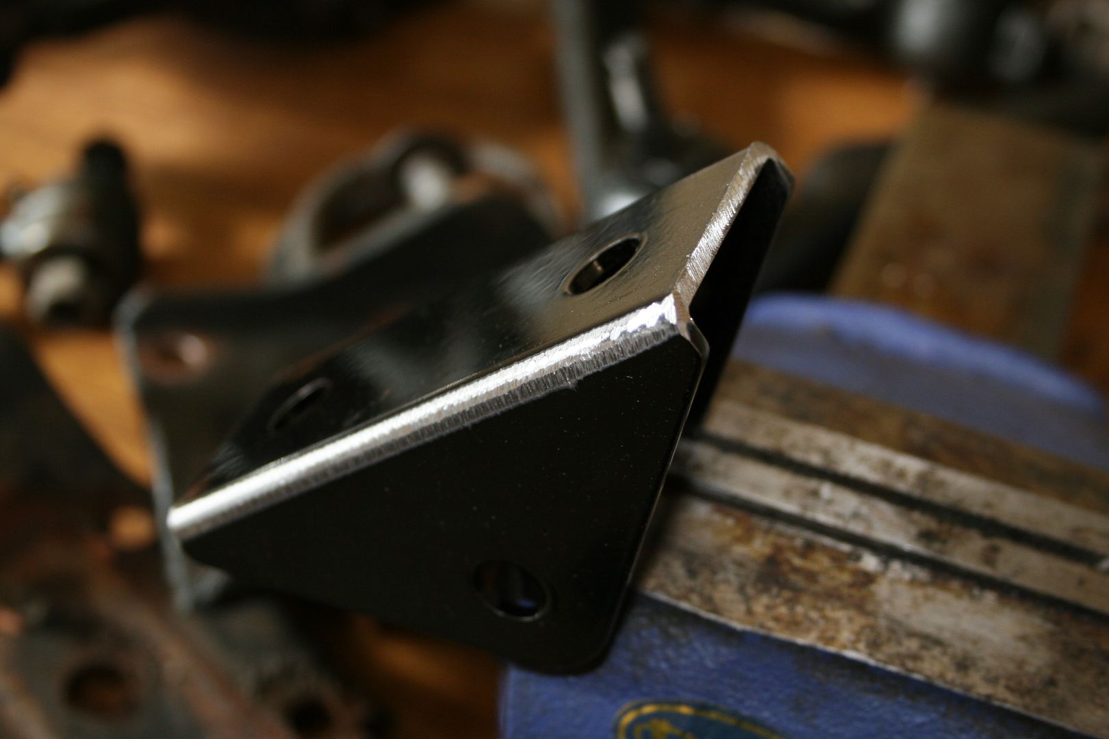 0
0 -
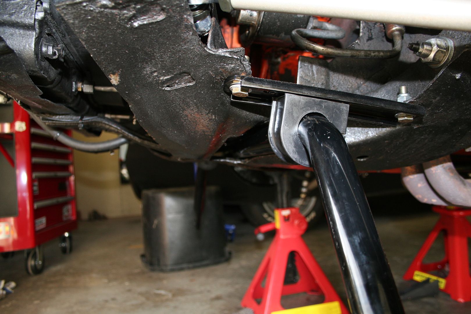
Then I did a test fit of where the subframe connector will bolt up, it bolts to the bracket that holds the front of the rear spring onto the car, the connector must be jacked up under a fair bit of load to meet with the frame where it is to be welded, once I had it on place I marked off where on the frame the front bracket is to be welded


Then I cleaned off all the areas that will need some welding, the bolts that hold the rear spring bracket need to be welded to the end of the connector
Then I started to clean up where the bracket for the subframe connector will weld onto the front frame
& the end of the connector will need to be welded to the bracket that connects it to the car itself
I’ve removed the pitman & idler arms from the steering also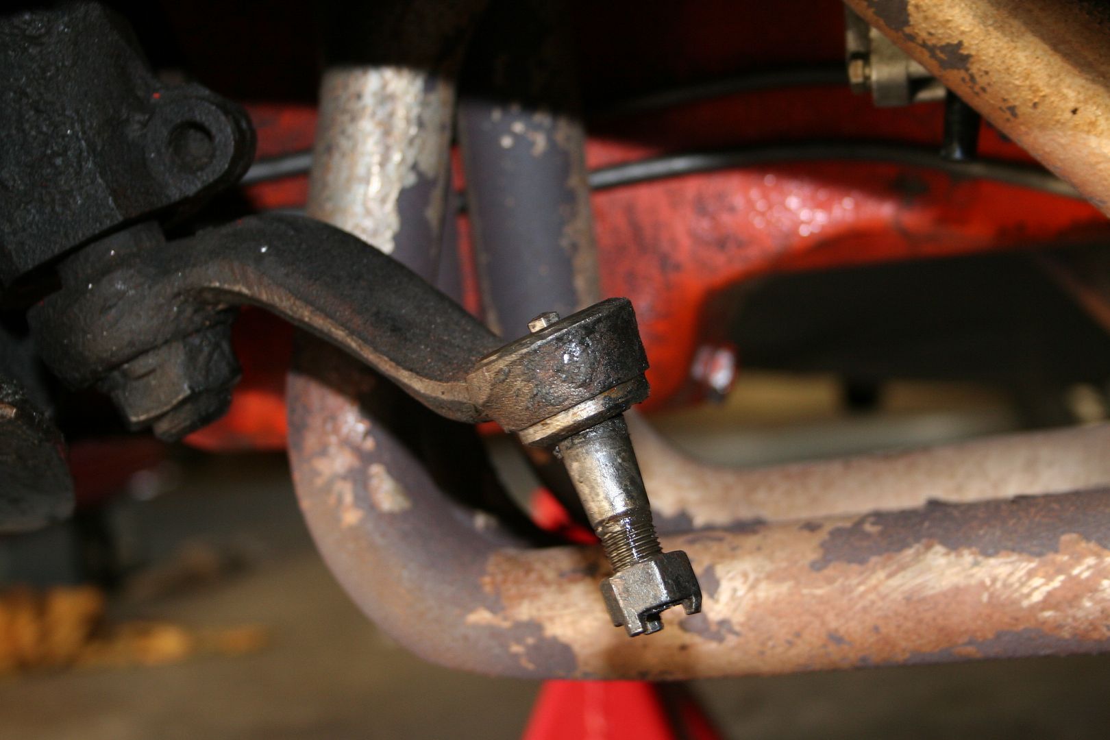
I have a brand new steering box here for her & I’m thinking that I might have a look & see what’s involved in swapping that over whilst the car is in the air & all of the steering arms are off anyway..
All that was left then for the afternoon was to start cleaning up any & all parts that are to be reused on the car like the leaf spring brackets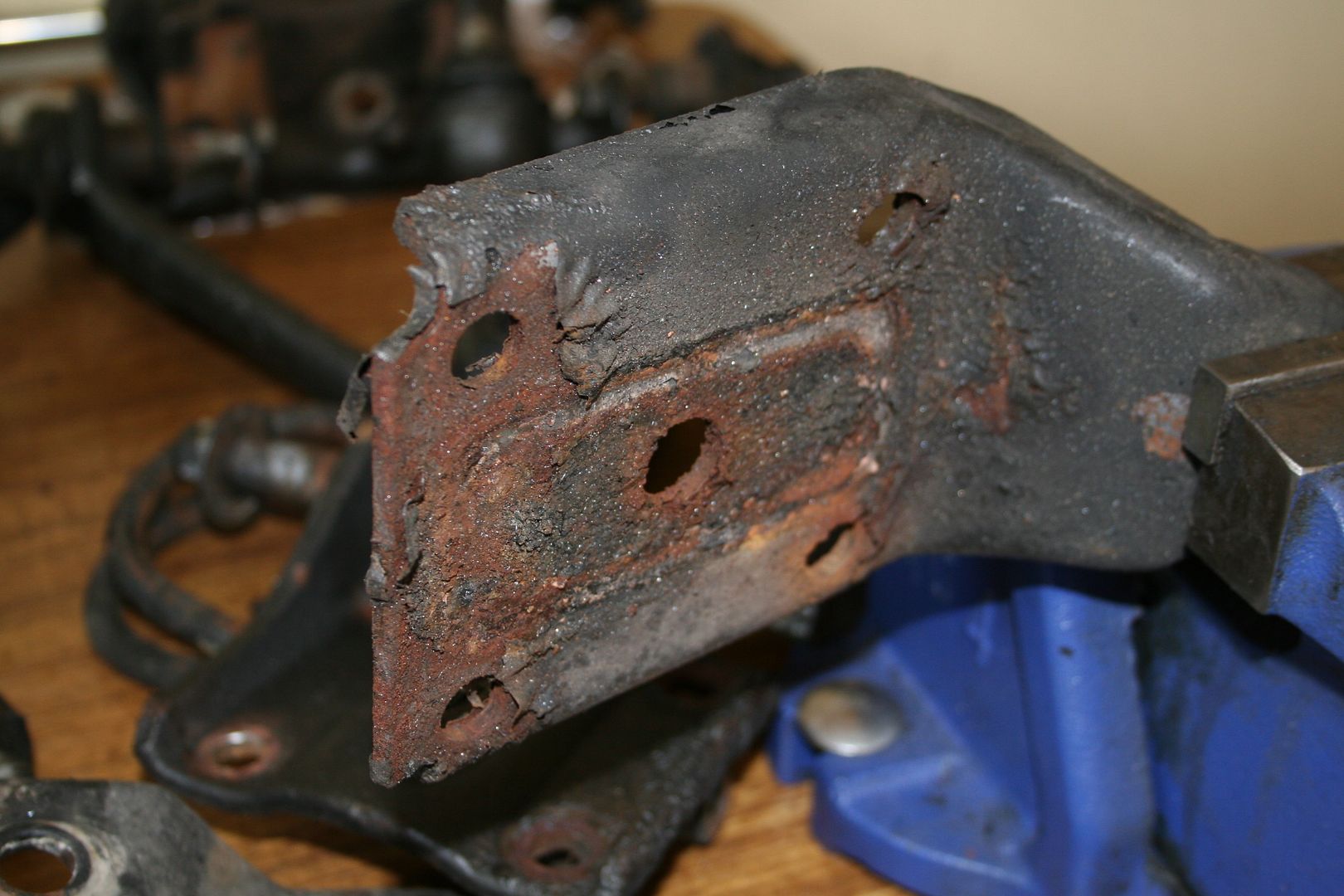
 0
0 -
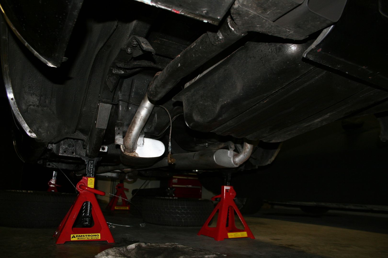
That’s where things stopped for a bit as I had a busy few weeks with work that saw me travelling back to Cork for a bit & then I went to the US for 2 week with my brother to drive Route 66 again.. so I’d lost weeks on this project now… I plan to put some hours in this week to get the bloody thing back on the ground on it’s own wheels again.
So first things first I found someone who knew how to weld & they agreed to spend an evening under my car welding on the new brackets for the rear sway bar & also welding in the sub-frame connectors that are park of the kit I ordered.
The two halves of the brackets where welded together on the bench before measuring them up for the final fitment & welding onto the rear chassis rail

Next up was the test fitment of the sub-frame connector,

The way this fits is that you need to weld in the bolts that go through the frame & also hold the bracket for the rear spring on
Once we where happy with the fitment & the alignment we welded the bracket onto the end of the connector
Then I splashed it with a quick blast of paint as I knew it would sit like this now for 5 weeks or so… I’ll sand this back later & put a better finish on it.
All welded up… no going back now unless I’m willing to grind these off 0
0 -
Next step was to properly clean up & paint all of the old bits that are actually going back onto the car


Then just before I was set to ship off for a few weeks of travel another box of goodies turned up… I need to replace the seat belts to meet the Australian ADR’s & I really didn’t want to go with the crappy black plastic ones with the bright orange button… I did some research & found a company in the states called Morris Classic Concepts in the US & they advertised that they sold set of replacement seat belts that look original but meet all the new standards including the Australian ADR’s & they make the kits specific to your car, so they are not a one size almost fits all.. so I ordered a set of fronts for the Challenger… sadly they don’t make the rears yet
I really really like the fact that I can have chrome, as I often say sometimes it’s the smallest of things
Proof that they meet the Aussie standard AS2596 0
0 -
We had some dinner guests coming over last night so I only had an hour that I could spend in the garage bolting stuff back together as apparently people don’t want to eat dinner in a dirty garage (or so I was told).. I started with the simple bits, so bolted the new idler arm on


I wasn’t planning on replacing the pitman arm on the steering box this time as I will be pulling the engine at some stage to replace the whole steering box… but that plan was foiled by muppetry on the part of a past owner.. instead of using split pins that can be easily removed to secure the castellated nut on the pitman arm they hammered a nail thru & then cut the ends off making it almost impossible to get the bloody nut off & completely impossible to reuse the pitman arm now… if you look closely at the pic below you can see the what’s left of the nail jammed into the hole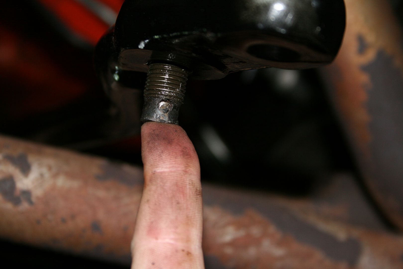
Next up was to reassemble the lower control arms, so I installed the new bump stops & got all the bits I need to install the new pivot shafts
I really like the design of the new pivot shafts they are hollow to allow for the fitment of a grease nipple in the end & you can see in this pic one of the two holes in the shaft next to my thumb
Had to press in the new metal sleeve, the rubber & then the actual pivot shaft itself, using my bench vice, I really must buy a proper press.. all the parts in the kit came with their own little packets of grease or super grease as Hotchkis label it & I gotta tell ya it felt very tacky & not grease like at all… but its what the makers recommend so I lubed everything up

Then I installed the lower ball joint & loosely installed the adjustable strut rod, both lower arms are now ready to go..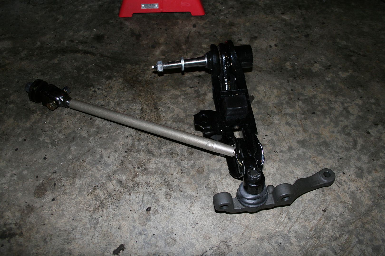
Looking at it I think it has to be installed a single unit.. if I put the lower arm on & bolt it up I don’t think there will be enough wiggle room to be able to install the strut rod, so I think this is how I’ll bolt them in.. with a bit of luck I’ll get to spend a bit more time & get more of this puzzle back together0 -
Advertisement
-
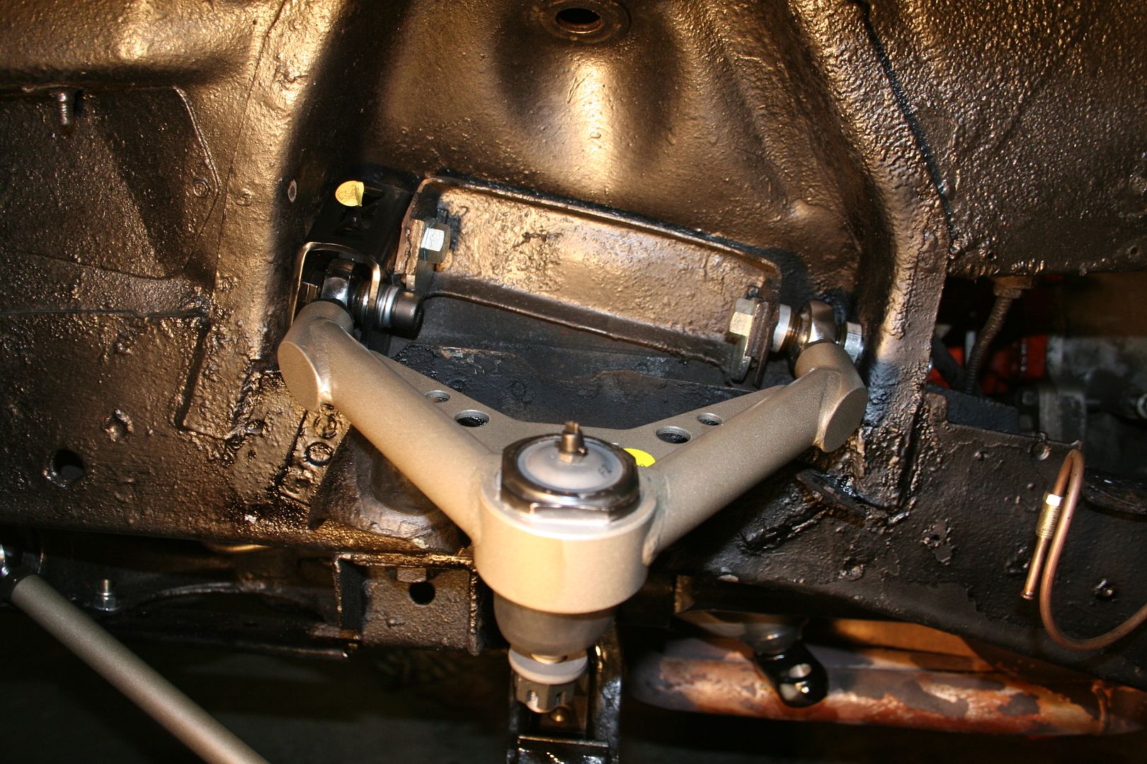
I made a decision on Saturday to concentrate on getting the back end of the car back together as I would have to move the front axle stands further back under the body to be able to reinstall the lower control arms at the front & I didn’t like the look of how that would have the front end balanced so the rear springs & the diff was the goal I set. Getting the old bushes out of the chassis rail where the rear shackles mount was easy to do, but getting the new ones in was a massive pain… they were so tight to get in & there is so little room to get your hands on any tools up there.. so it took longer than I’d like to admit to get the rear shackles on & the springs hung at the rear

Then simply swung up the front bracket, which had to be fitted to the spring before installing the spring as there isn’t enough room to install that bolt if you mount the front bracket to the body first, of course this way made it bloody hard to tighten the top two bolts on that front bracket
One spring in
Both in
Now I had a few different ideas as to how best get the diff back in, the last time I fitted a diff was in my XB & as I’d never done it before I had asked some people for advice & I was informed that the best way to do it was to fit the springs to the diff & to lift the whole thing as one into the rear & bolt the springs in… this did work on the Ford but it was a lot of weight to shift about.. now with the rear valance panel in the way on this car I decided to try something different, so I fitted both springs as you can see above.. then I slid the diff under the car on my floor jack & jacked up one side until it was high enough that I could slide the brake drum up through the gap between the spring & the car. Then I was able to rest the diff on one spring & jack up the other side until it was at the same height & then simply slid the whole diff sideways until it was sitting on the correct pins on the springs.. normally I like to take pics of things as I go.. but balancing the diff whilst moving it meant I could never let it go to take a pic of the install process that I’ve just described… sorry.. once the diff was sitting on the locating pins on the springs I then fitted the brackets with the new U-Bolts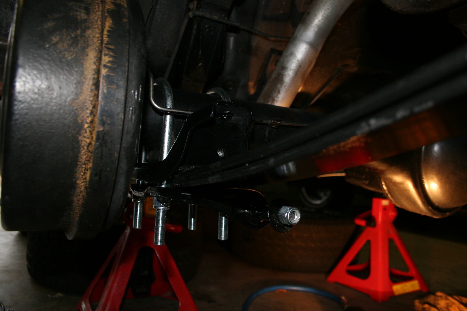

Loosely first then tightened them all up once I was positive the Diff was sitting where it should be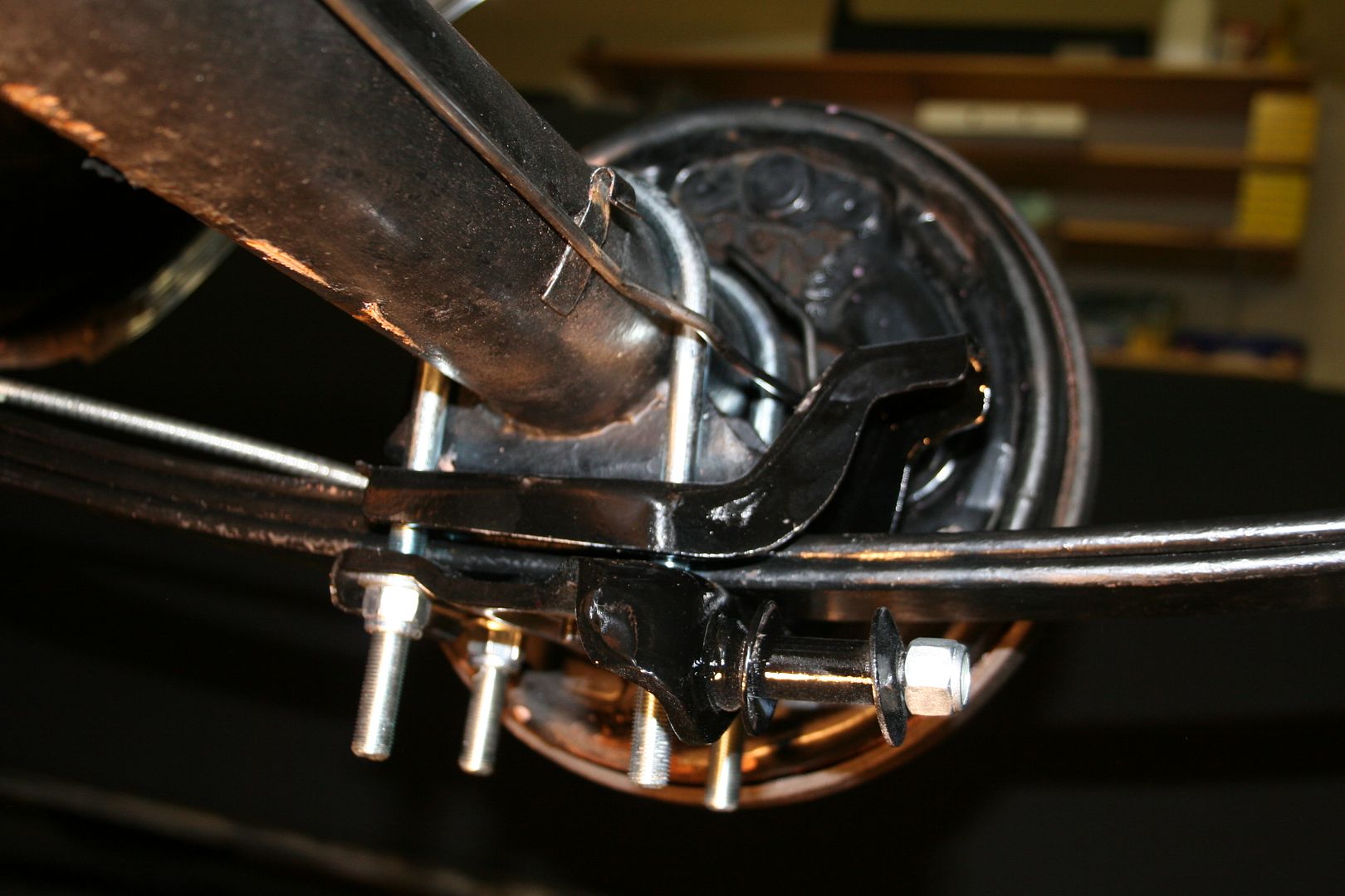
With the Diff back in she’s starting to look like a car again… happy man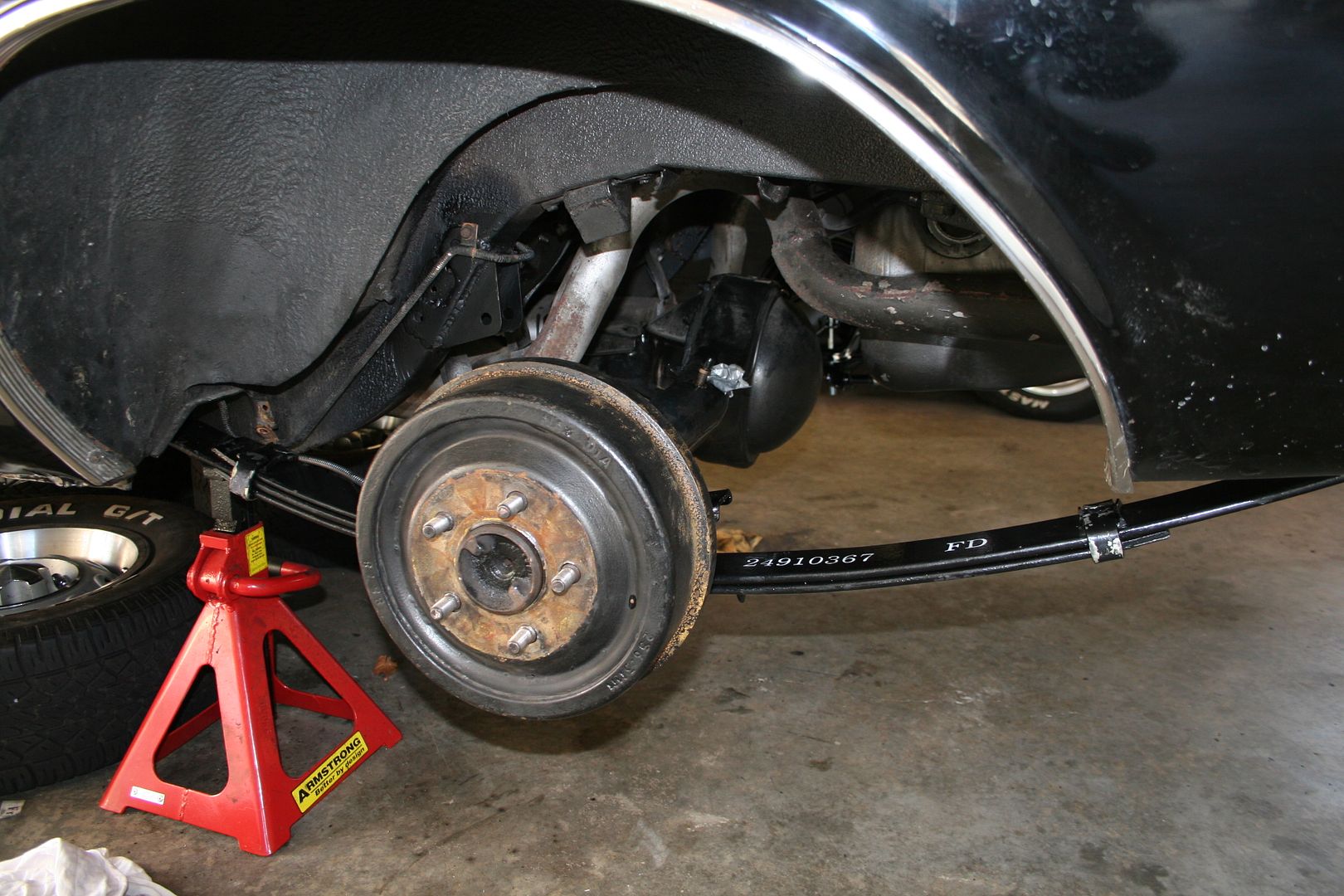
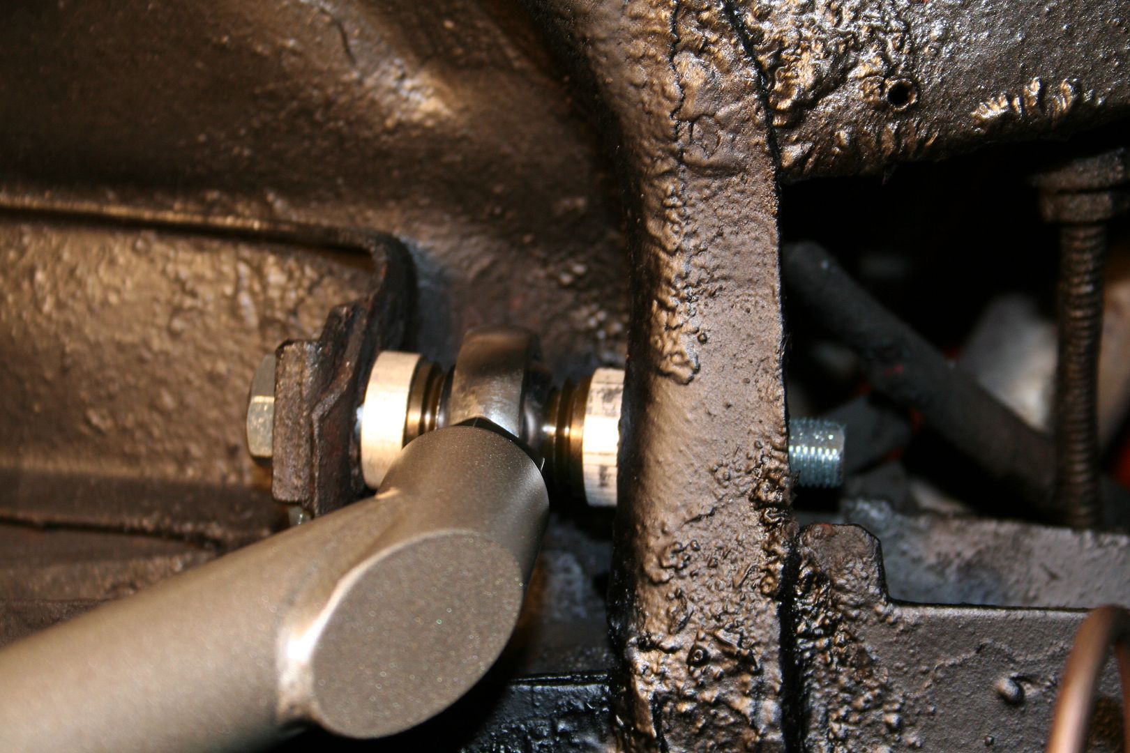
Next job was to install the new rear sway bar, so bolted the dog bones to the newly welded in brackets first
Then I hung the bar off the bones to see how the bar would be sitting before tightening up the new hangers that connect the sway bar to the diff

Now the nice people at Hotchkis put stickers on these new parts & I had already noticed that with the two sub frame connectors one of the stickers was correct & the other one was upside down, that wasn’t an issue with the sub frame connectors as they can only fit on the car one way anyway… but when I was test fitting the sway bar I assumed that the correct way up for the bar to attach was to have the Hotchkis sticker be the right way up.. but once I’d done that I sat back & it just didn’t look right… the bar was sitting nearly 4”s below the diff housing…

So lucky that I hadn’t just tightened up all the nylock nuts as I went & I actually just test fitted it first… so off it cam again & then back on with the sticker upside down… but at least now the bar sits across the diff face as it should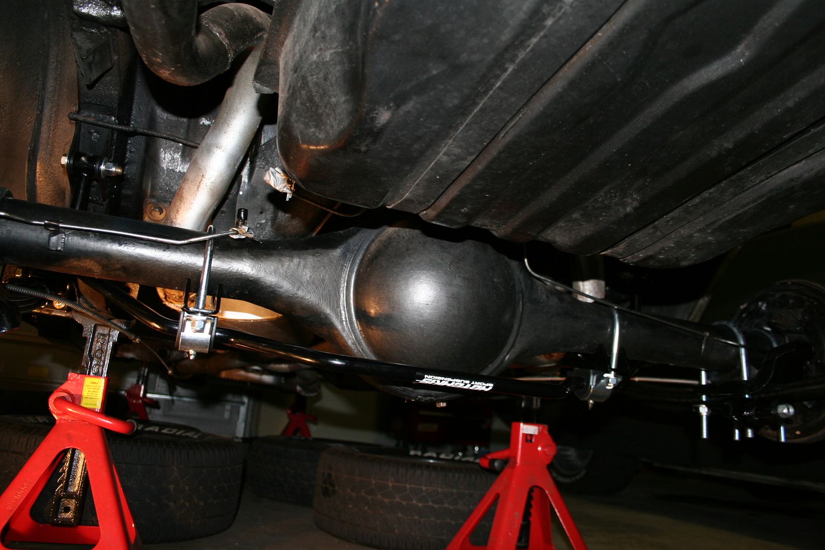

Now it’s just the simple task of reinstalling the rear shocks, hooking up the handbrake lines & the brake lines & then refitting the drive shaft… so she should be back on her rear wheels this week when I get an hour alone in the garage-1 -
Not a massive update with regards to how much work was done last night, but in-between conference calls for work to the US I did manage to reach the milestone I wanted to get to this week… the car now has two wheels on the ground.. & I’m a happy man..
So I cleaned up all the connections & reconnected all the brake lines for the rear
Then installed the rear shocks back in, I’m using the same ones I pulled out as they are new anyway.. I only fitted them not long after I had the car
Then I reconnected the new handbrake cables to their brackets & bolted the driveshaft back on
Then I was able to finally bolt the wheels back on.. it’s starting to look like a car again now
Then for the first time in months I was able to lower the car back onto a set of her own wheels… the new suspension setup will lower the car somewhat, I won’t know how much exactly until the front is on the ground again.. but it looked very low to me last night… although this may be because I’m used to the boot being at chest height for the last few months.. I did the bounce test when she was on the deck & the rear actually moves up & down now when I push on it.. the old springs where so far gone she rode like a hardtail with no real suspension travel at all

Now to move onto the front again… sadly I don’t think I’ll get much time this weekend as we have some plans but I hope to get a bit of time… I’ve also been studying the steering box for a while now.. the one in her is stuffed & has a lot of slop that can’t be adjusted out… I have a new box under the bench in the garage but I’m not 100% sure that I can get the box out with the extractors that I have fitted… but I’ve decided to give it a go whilst everything else is off the car, if the extractor has to come off then so be it..0 -
Decided last night to tackle the steering box swap… now I was all set for this to be a big awkward job that took four times longer that you’d think, I read a few reports on forums about how hard this job can be & how I’d have to remove the drivers side extractor and/or the battery & it’s tray to be able to get the thing out & how it’s so easy to damage the coupling on the shaft etc… but to my happy surprise this was a very simple job & everything went much smoother than I had any right to expect it would.
First step was to remove the pin from the coupling on the shaft, I was expecting this to be well stuck & possible rusted in place by now.. but a few taps with the correct size punch & it just slid out nicely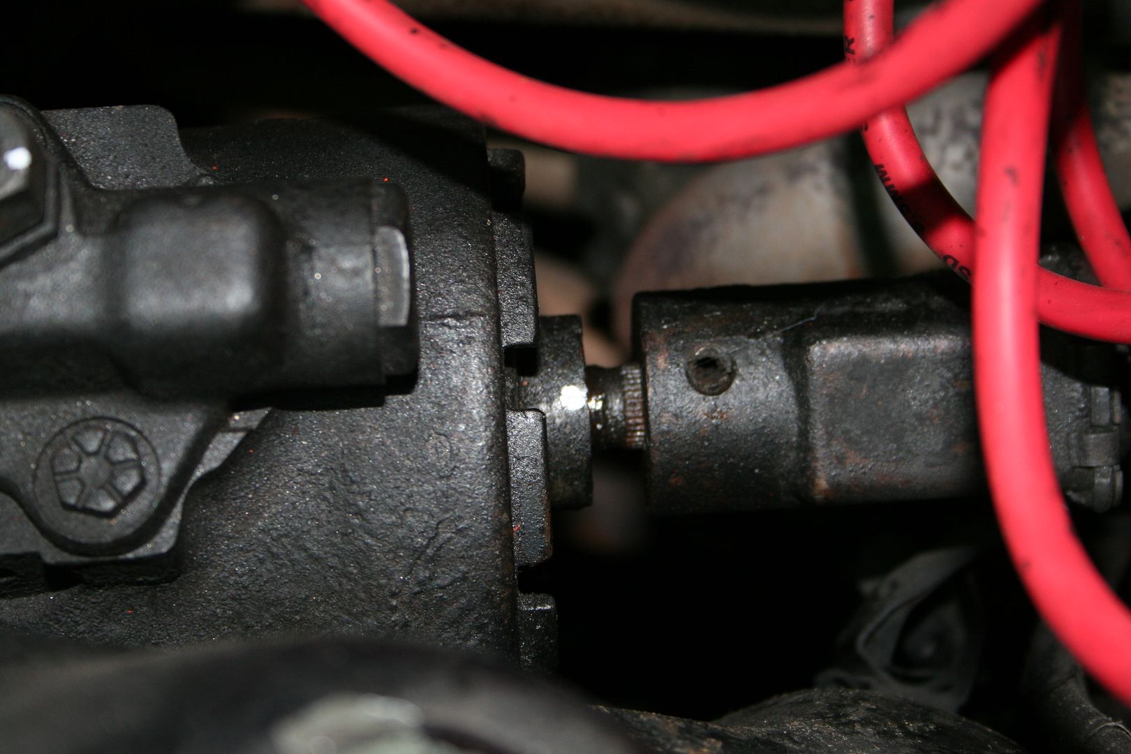
Once the pin was out there is some movement on the coupling that allows you to pull it back, it won’t come back enough to slide off the shaft completely so it was into the car & I undone the 2 bolts on the saddle that holds the steering column onto the underside of the dash & then undid the 3 bolts below that hold the column to the firewall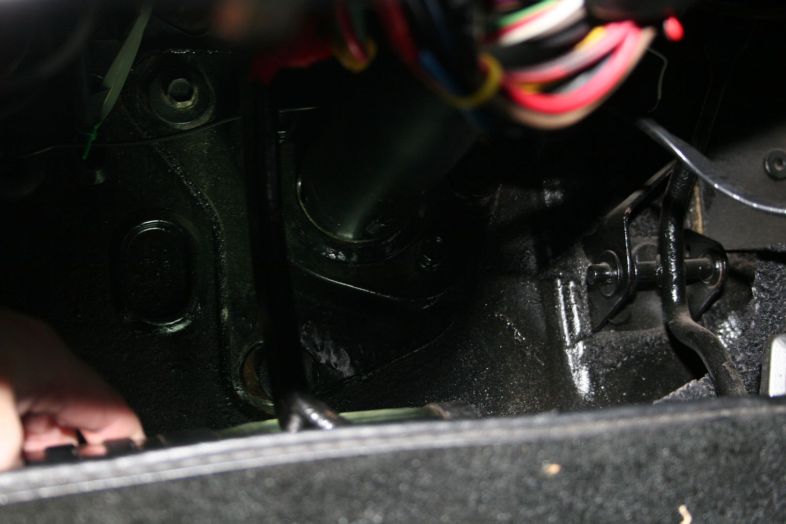
Once these 3 bolts are undone you can pull the steering column back into the car that final half inch & then the box is free of the coupling on the shaft… too easy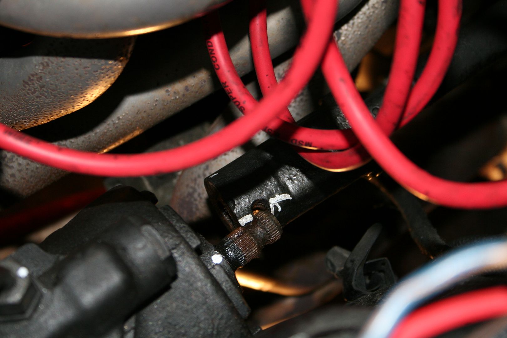
Then I disconnected the high pressure & the return lines from the power steering pump & tied them up out of the way
Then I undid the 3 bolts that hold the steering box onto the K-frame & as I was wiggling the box about to get it free the thing nearly fell on me it popped right out… I had hear horror stories from others about having to remove extractors or the batter tray to be able to get it out… but I guess having the lower control arm & the torsion bar out made the job super easy… once it was out I cleaned up the surface that was now exposed
Old vs new
Installation was super easy too, it slid right into place & bolted up no hassle at all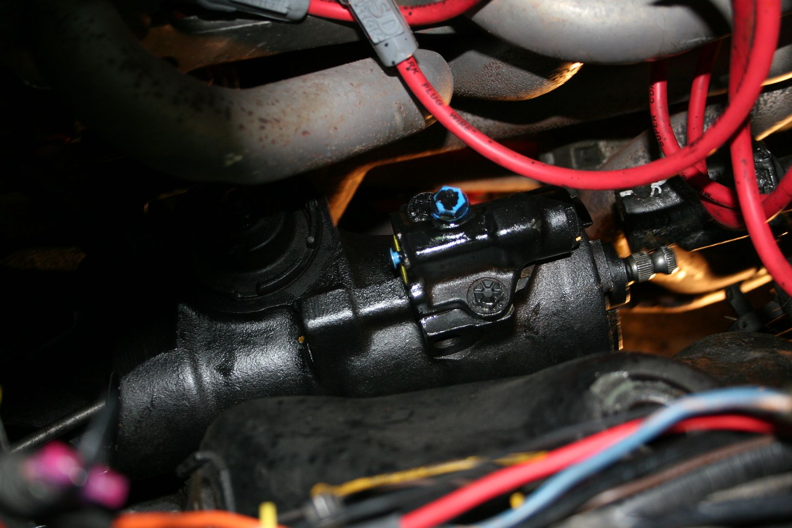
Then I simply lined up the coupling to the shaft correctly on the master spline & pushed the steering column back down to it’s correct position tight against the firewall to get the first half inch on, the just tapped the coupling home with a rubber mallet & reinserted the pin, again all too easy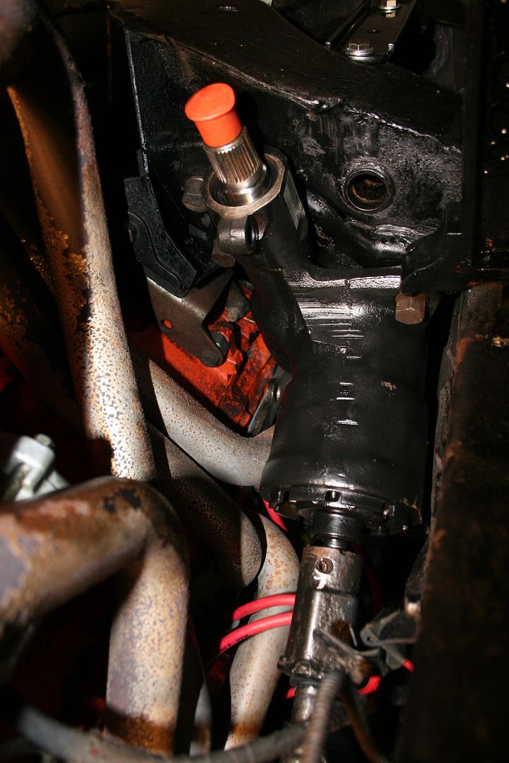
The new box didn’t come with the connectors for the high pressure & return lines for the power steering pump to hook up to, so I removed them from the old box…
I’ll clean these bits up on the weekend & I also plan to remove the pump & drain all the crappy old fluid out & give the whole unit a good clean & a paint before connecting the system back up… onwards & upwards now, if I get some free time on the weekend I may even be able to get the whole front end back on & have her on all four wheels again… can’t wait…0 -
So I had a bit of spare time on Saturday & I managed to get the lower control arm, strut rod, torsion bar setup onto both sides of the car… whilst none of that was difficult really as it’s shiny clean new parts now going onto a clean K-frame you kinda need the assistance of a mechanically minded octopus to get this stuff on… the design of the how the strut rods sit into both the K-frame & the lower control arm means that they have to be installed as one piece & then halfway thru moving that assembly into it’s final resting place you then have to ram home the torsion bars… like most things with working on cars.. the time required the install the 2nd one was a fraction of the time required to install the first..
I started by measuring the old outgoing strut rods & adjusting the new ones up to that length so that I’d be close to the correct adjustment needed when the wheels finally go one
Then I cleaned up the K-frame hole where the strut bolts into
Test fitted the strut rob to ensure that once I tightened it up the joint would be aligned the correct way, then once I was happy bolted up the K-frame end leaving the rod hanging

So I slid the lower arm pivot shaft into the pre-greased slot in the K-frame & then as it’s about half way home you slide the end of the strut rod into the control arm & then slide the whole assembly forward as far as you can.. it won’t go the whole way home until you start tightening the pivot shaft bolt up… you can also see my newly installed pitman arm on my new steering box in the pic below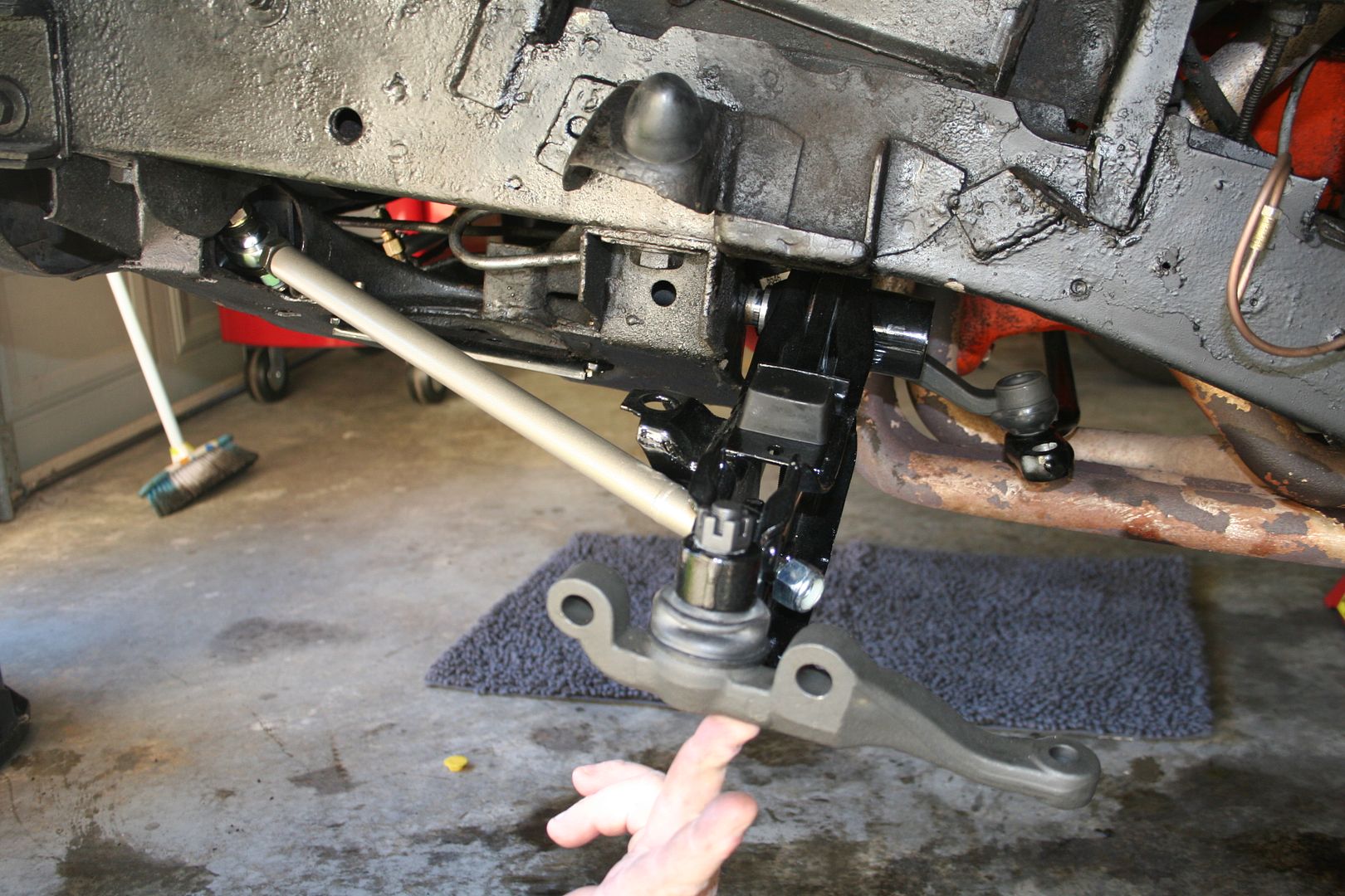
Then I discovered that you cannot tighten up the nut on the control arm pivot shaft if the torsion bar is not installed.. I could get it 90% but then the pivot shaft would just spin in the K-frame rather than pull the lower arm in tight. So I slid my new torsion bars thru the cross member of the chassis & up to the lower arm, then greased up both ends.. I was expecting this to be a tight fit to be honest then new bar pushed in by had with a little help form a soft hammer so I was very happy that I didn’t have to belt the crap out of the new bars with my torsion bar removal tool & scratch the nice paint finish
Installing the torsion bars pushed the pivot shaft of the lower control arm fully home & then I was able to do up the nut call that job done… I forgot to take a pic of the new retaining clips at the rear of the torsion bars & the protective boots.. but I’ll do that as part of my next update later in the week

Hmmm looking at the above pic just now… I’m not happy with the exhaust at all, it looks too bad to stay on the car, plus the extractors are damaged & flattened at the bottom from some previous owner doing dukes of Hazzard jumps or something… so I’ll let them hack the system to put some extra mufflers on to get the car past road worthy noise checks & then I’ll get a whole new system installed
So it’s looking more & more like a car everyday now…0 -
I finally managed to get a few hours out in the garage last night… I really need to win the lotto I think.. the fact that I have to work to get the cash to do these projects is seriously getting in the way of me getting the time to do the project, classic catch 22 I guess you’re either cash poor or time poor when doing these things.
I have had a bit of a set back with regards to my plans for the brake upgrade for the Chally… I had originally found a great deal on a set of Willwood disks & callipers, they were 4 piston rears & 6 piston fronts.. then when I was having a discussion about these with an engineer I found out that the 6 piston jobbies don’t have a rubber seal around the piston head & as such that makes them non compliant for use on Australian roads… they would work great but the ADR’s require the rubber seal as apparently people here don’t clean the pistons before pushing them back into the calliper when changing the pads… so now the hunt is back on for a decent brake upgrade kit, the guys at Pentastar Parts have been great thru this & they are currently working with their suppliers to get me a set of 4 piston front & rear callipers that do have the rubber boots on the pistons to keep my engineer happy.
Now because I don’t want to delay this project any longer I’ve bought some new brake bits so that I can put the old stuff back on & have it actually work.. the rear cylinders where leaking on both drums so I got a new set to replace them & the master cylinder was leaking front to back so a new one was ordered too & because I like shiny things I opted to get a fancy cover to go on the top

So tonight’s was to finish putting the front end on.. I started by measuring up the old upper control arm so that I could get a base setting for the adjustable arms on the new ones, whilst everything is adjustable & that’s fantastic the design of the upper arms really means that to adjust this after they are installed on the car actually requires the cam bolts that hold the arm to the body to be removed so that you can adjust the joints in or out
Because of the design of the new arm & the way that it has a spacer block that moves the front leg of the arm out & down from the stock position means that the original bracket is actually in the way & the bottom corner needs to be ground back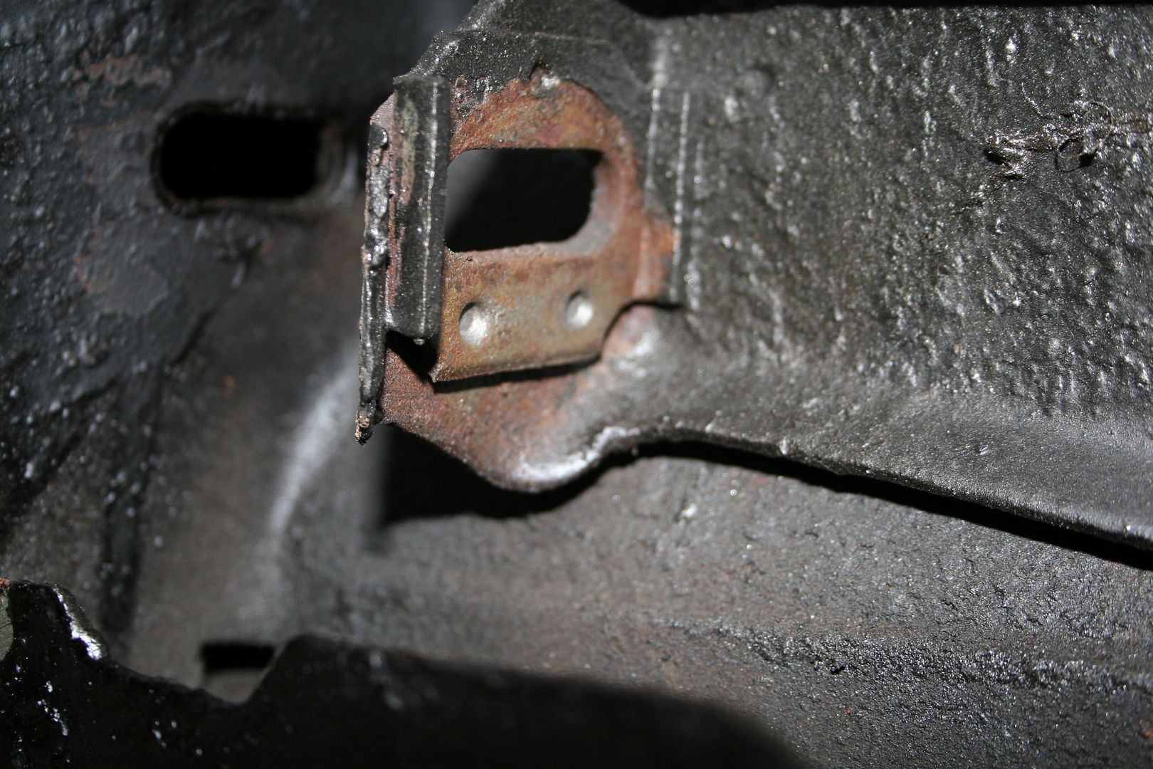
A little bit of work with the die grinder & I took off the least amount of metal possible that allowed the arm to sit in place

Once I had this ground off to allow for a nice fit I then installed the new cam bolts, I guess I could have reused the old ones but I figured if I’m doing this I may as well fit all new hardware where possible… plus its nicer working with new clean bits rather than old greasy parts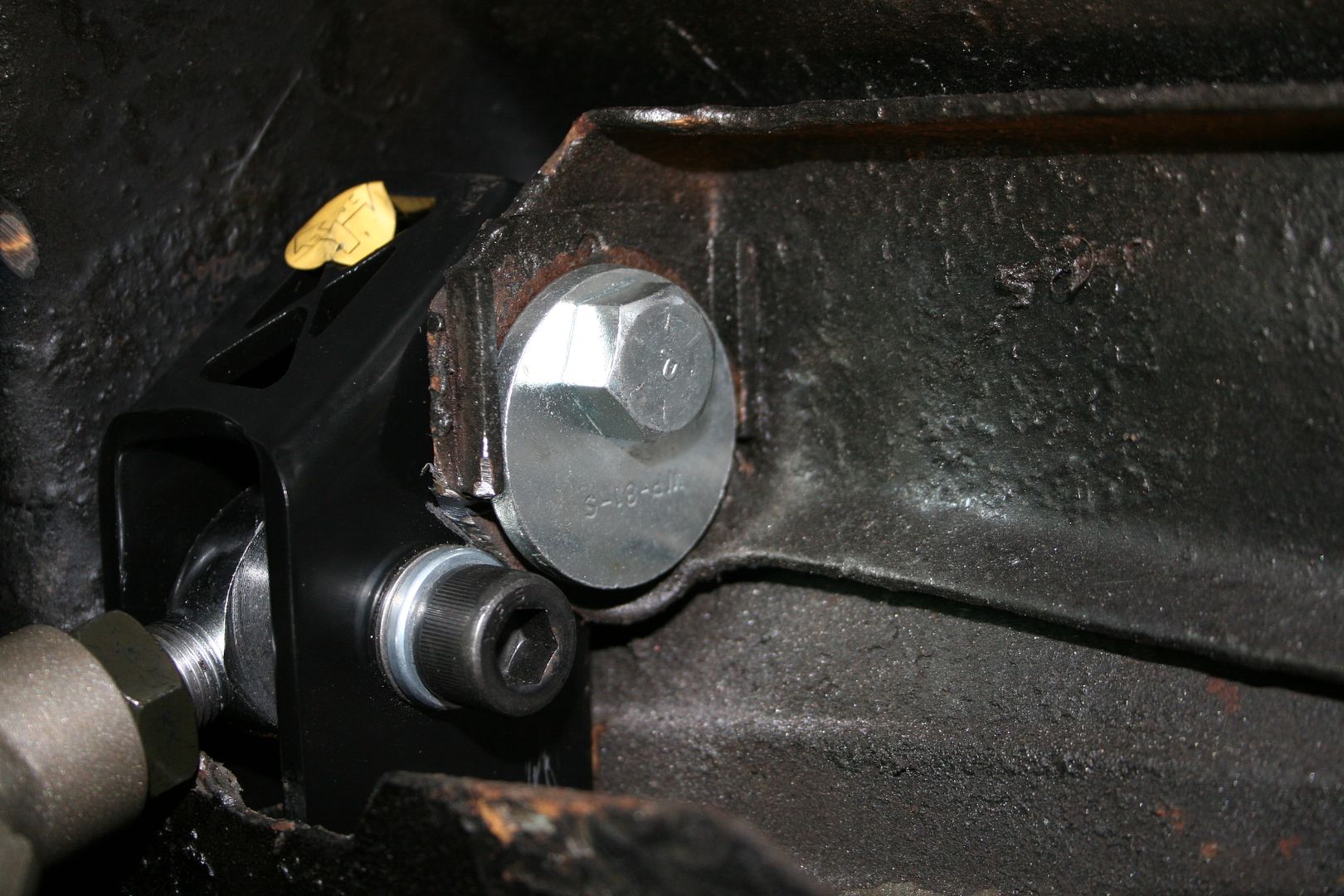
Now because the joint end for the rear leg of the control arm is narrower than the stock leg of the stock arm the kit comes with a selection of spacers for you to pack out the difference
 0
0 -
& that’s it… the upper control arm is now in

The next step was nice & simple, just reinstall the front strut back in… this moment made me smile as it suddenly looked like front suspension should, best two bolts I’d put on all night
Next up was the tie rods.. same as upper arm, I started by measuring them against the out going old parts so that the car will be close to drivable when it’s back on the ground before doing a wheel alignment.. once I had the tie rod at the right length I then bolted up the inboard end first.. the aftermarket extractor set up on this car is mad, the steering arm goes thru it & the clearance here is measured in mm.. I plan to replace the exhaust some time later this year, I might look into other options to see if I can get one that fits a bit better than this one
Then I bolted up the outer end, again as with a lot of parts on this kit which are looking to both use the existing pick up points & correct/improve the geometry at the same time spacers are installed here
All done

The final step for the night was to bolt the spindle back on, this is not a new part I’ve just painted the old one as the spindles where fine when checked
Once that was done I jacked up the whole lower assembly to somewhere near level & then attached the top ball joint to the spindle… job done..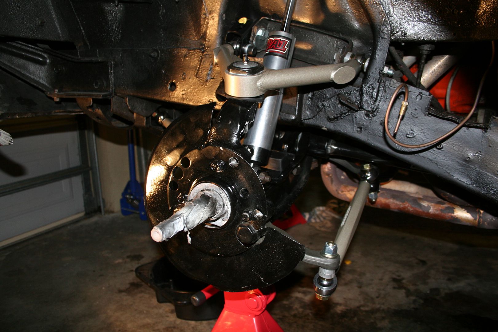

Saturday morning I’ll put the passenger side back together & then I’ll fit the new front sway bar & that will be it… I’ll refit the old brake disks for now as I don’t want to leave the car off the road any longer now that I must0 -
Advertisement
-
So a bit of time was had in the Skunk Works garage on the weekend, so the passenger front went on… you know how when you’re working on cars often times one side is friendlier that the other.. well for the rear the easy side was the drivers & now at the front the easier was definitely the passenger… the original bracket didn’t need near as much grinding to allow the new control arm to fit in

Getting the nut on the cam’d bolt was awkward as there is so much on this side of the engine bay now
When fitting the other side as before there is a set of different sized spacers supplied as the kit explains that no two Dodges are build the same… & they are spot on the spacers needed for this side where different to the drivers side, proving that the tolerances are pretty big on this car.. once I measured the gap & worked out what spacers where needed it was then the fun task of actually trying to align the control arm, the cam bolt, two alignment bushes & 4 spacers… remember that mechanically minded octopus I mentioned in a previous post… you need him here again… I found that a dab of grease held the alignment bushes in place on the arm & then if I installed the cam bolt just enough to hold the first two spacers on I was able to get the arm in without anything dropping….
Then being very careful not to knock anything I was able to slide the last two spacers in whilst sliding the cam bolt thru
After a bit of wiggling of the cam bolt everything was in….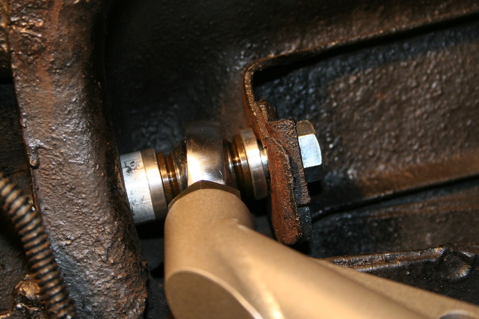
Arm installed
Shock reinstalled
Tie rod & spindle back on..
The last piece of this suspension puzzle now is the front sway bar… I greased & fitted the rubber mounts to the bar 0
0 -
Then back under the car again… the sway bar set up on the Challenger is different to other muscle cars I own/did own in that it actually goes through the middle of the K-frame.. so I installed the bar through the K-frame.. this was not easy as the new bar is 220% stiffer & therefore a lot thicker than the stock bar so it only just fit through the gap..

Bolted up the saddle that holds the bar to the K-frame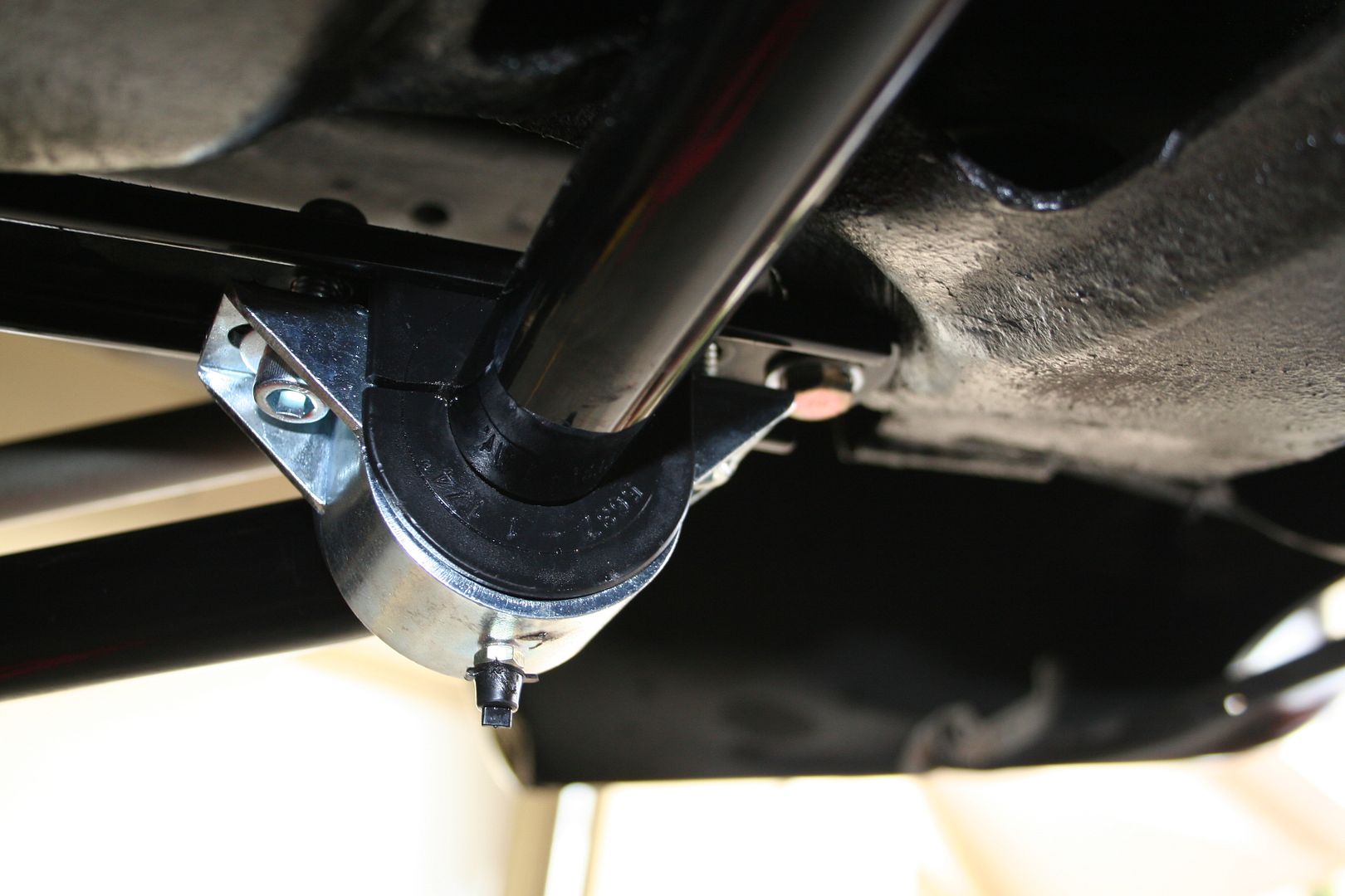
Then bolt up the ends to the lower control arms..
& that’s it… all of the suspension has been replaced now… all that’s left to do is to fit the brakes & get an alignment done… it’s been a long project to do this but it’s been great fun.. I’m actually worried that when the car is back on the road I’ll miss working on it… might be time to start working on that spare XB Coupe shell I have… maybe a track car project would keep me busy 0
0 -
Now that I hopefully done with spending hours on my back under the car I’m focusing on some of the bits up top that need to be sorted… I decided to swap out the brake master cylinder for the new one that turned up last week… nice simple job this one as the brake lines are all already empty as the disks & callipers are off the car… so I undid the two brake lines & the 4 small nuts that hold the master onto the booster
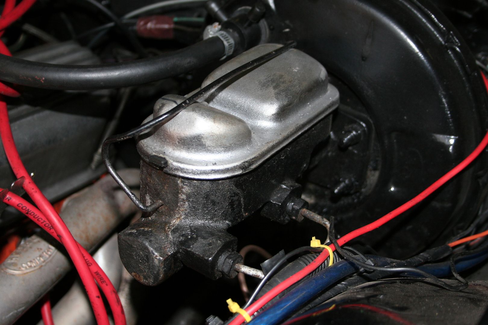
Slide the old one out
Compare the old to the new on the bench to be 100% sure I’m not going to have any alignment issues
Bolt in the new one & redo up the lines… too easy 0
0 -
Next job on the to do list was to flush out the old power steering fluid… I noticed when I was swapping the steering box that the fluid was brown & very crappy, so I decided that a flush was needed before connecting up the new steering box… so I had two choices, I could undo the hose from the back & let the old fluid drain out, I could siphon out the old fluid or I could bolt the whole unit off so that I could drain & flush it completely & clean & re-paint it & clean the engine block behind it… I’ll give you two guesses which option I went for…
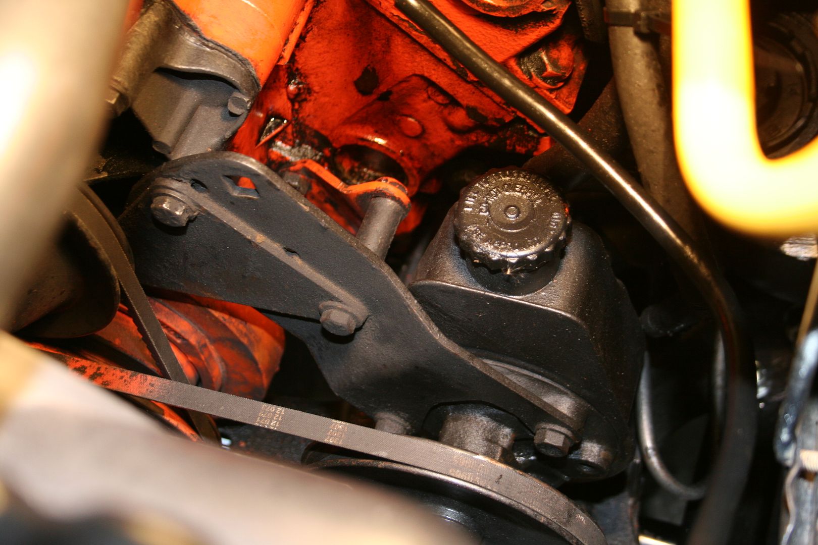
There are two bolts that have to be undone to remove the pump, the top one that is also the belt adjuster goes through the water pump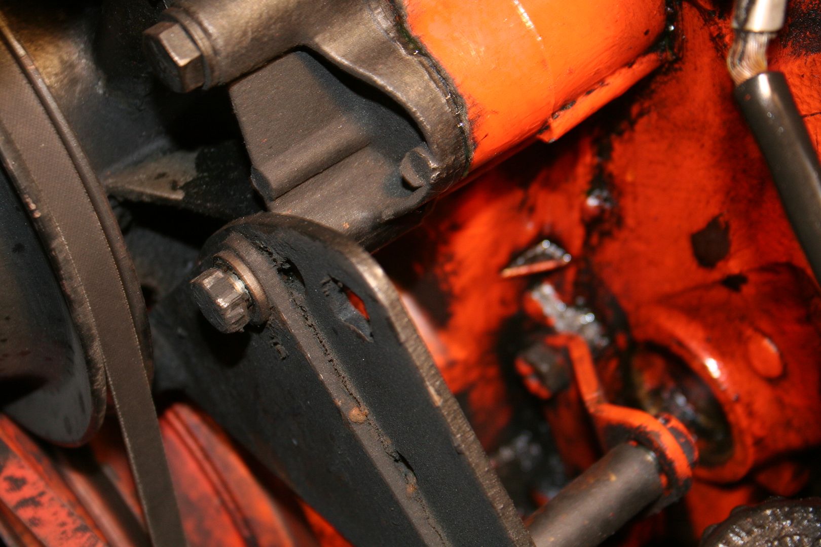
Now as I started to undo that bolt I noticed that there was a little drip of coolant starting to drip out… simply due to the bolt easing the water pump off the block I figured… no big deal I’ll do the bolt back up once I have the pump off…. If you look closely I managed to capture a drip
Now when I pulled the bolt out I must say that I was not expecting this at all….. I’ve unbolted the accessories off Fords lots of time & never once has this been the result
Luckily I had placed a catch bucket under the car when the dripping had started… I honestly never thought that that bolt hole would be a straight through funnel to the water in the pump… now that I have half the coolant out maybe I’ll replace the hoses… might look at the rad internals too… anyway, once both bolts where off wiggled the unit free
Carefully lift it out trying not to wash the garage floor with any more fluids that I have too… this will now be cleaned & painted before going back on
With the pump off you can see the mess behind that I now get to clean up during the week…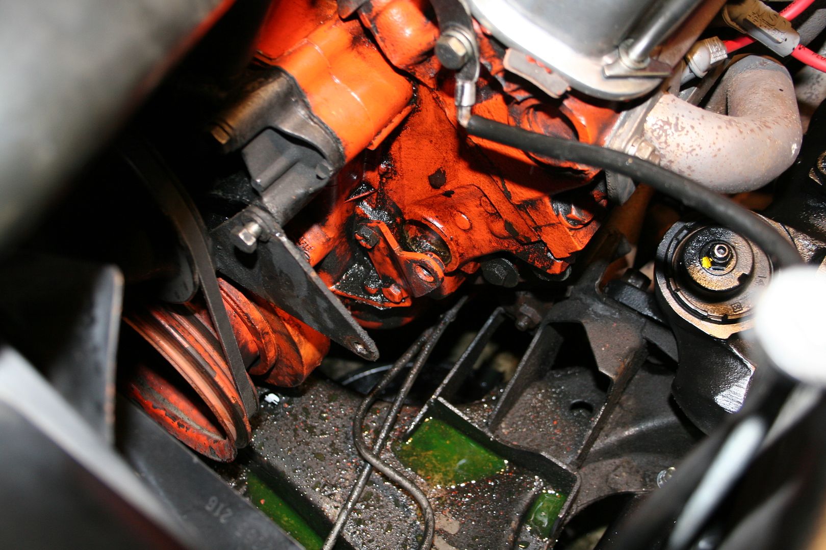 0
0 -
So with the pump off the first job was to clean all the years of crap off of it, so I sat it in a basin & sprayed copious amounts of degreaser on it… my plan had been to degrease it first & then see about stripping the paint… but the paint was so bad on it anyway that just the force of spraying the degreaser in it removed most of the paint… giving it a good brush over with a paint brush removed 90%


As I already know that next winters project will be to pull the engine & rebuild that with all chrome shiny accessories I didn’t go mad cleaning this up as it will be short lived on the car anyway, so I just repainted it & replaced the low pressure return hose, the high pressure line was fine
Got my disks back from a mate who pressed in the new bearings for me.. I must buy a press so I can do this stuff myself
Sat them on the spindle nicely so as not to push the bearings back out & it’s looking like a car again now….
Did up the centre nut & split pin & job done, too easy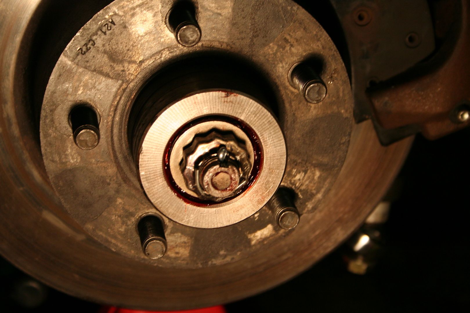
Then I reinstalled the callipers & hooked up the brake lines again
Then…. I had to pull the drivers side off again… bugger
I’d forgotten that when I went to pull the callipers off last time one of the bolts was only in two thirds of the way & had 4 flat washers on it to take up the slack…. upon inspection of the bolt you can see that half of it is covered in loctight & the first have of the threads are destroyed… they have been flatted completely… so I’m guessing that a previous owner cross threaded this & rather than stopping when doing the bolt up got hard they completely destroyed it & tightening it home as hard as they could…. What I love most is that they then must have noticed the error of their ways but rather than fix it they pulled the bolt & used the washers to take up the slack & then rammed it back it… top quality work…
 0
0 -
Advertisement
-
So I got my tap & die set out & I re-tapped the bolt hole… this took a while to do it slowly to not do any more damage, the amount of crap that came out was unreal, I did the re-tap in 4 goes.. here is the crap from one run
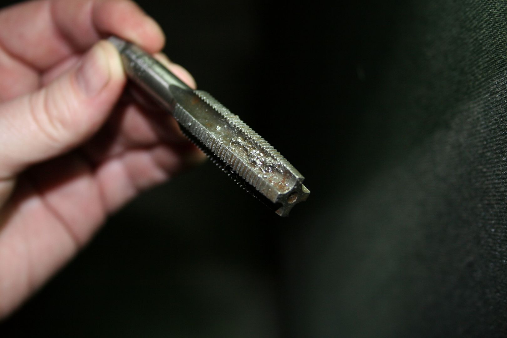
So now I have to get new correct bolts, all four where covered in solid loctight & all four has their heads slightly rounded.. so in the bin they go…..
I decided that this shouldn’t stop me getting the car back on all fours again, so I got my little digital camber gauge out & set the front suspension up to where I think it needs to be… I’ll do it properly once the wheels are back on
Then I put the wheels back on…. Look… it looks just like a car again… I was a very happy bunny… it’s been a long time since I saw the old girl on wheels…

Then I got the measuring tape out to see where the new torsion bars had the cars height as I’d just guessed the settings when I installed them…. Sorry the pic is in such bad light but after the drama with the brakes it was a little later that I had planned on it being..
The result… too low… not out by much but 3.5”s to the lowest point which are the drivers side extractor & also the flange where the extractor bolts to the collector… so I started to play around jacking up the front to see what sort of heights & stances I liked before adjusting the torsion bars to raise the car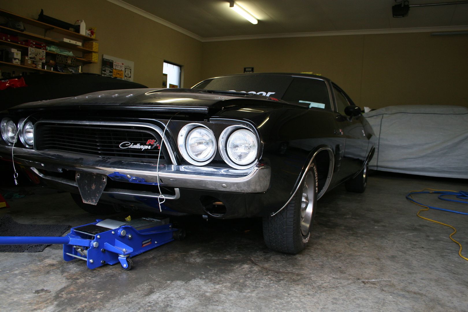

Now I thought I’d taken a pic of the car at her final height, I raised it just over an inch, so it’s 4 ¾”s to the lowest point now & over 5 to the actual car frame… I take a pic in the daylight & post that up.
My mate popped round the other night with a late B’day present for me… as I’m a car nut & a car movie nut he got me a chrome duck like the one used in Convoy & Death Proof… so we test fitted it as the Challengers new hood ornament… I wonder what VicRoads would thing it I bolted this to the bonnet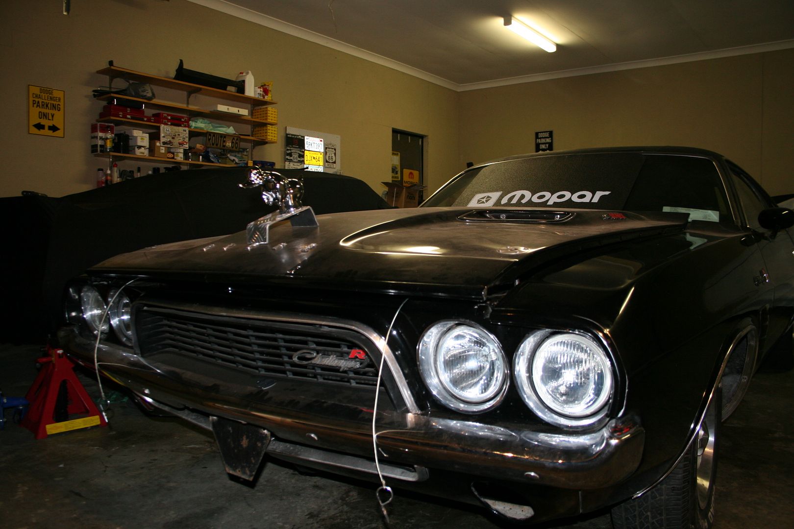
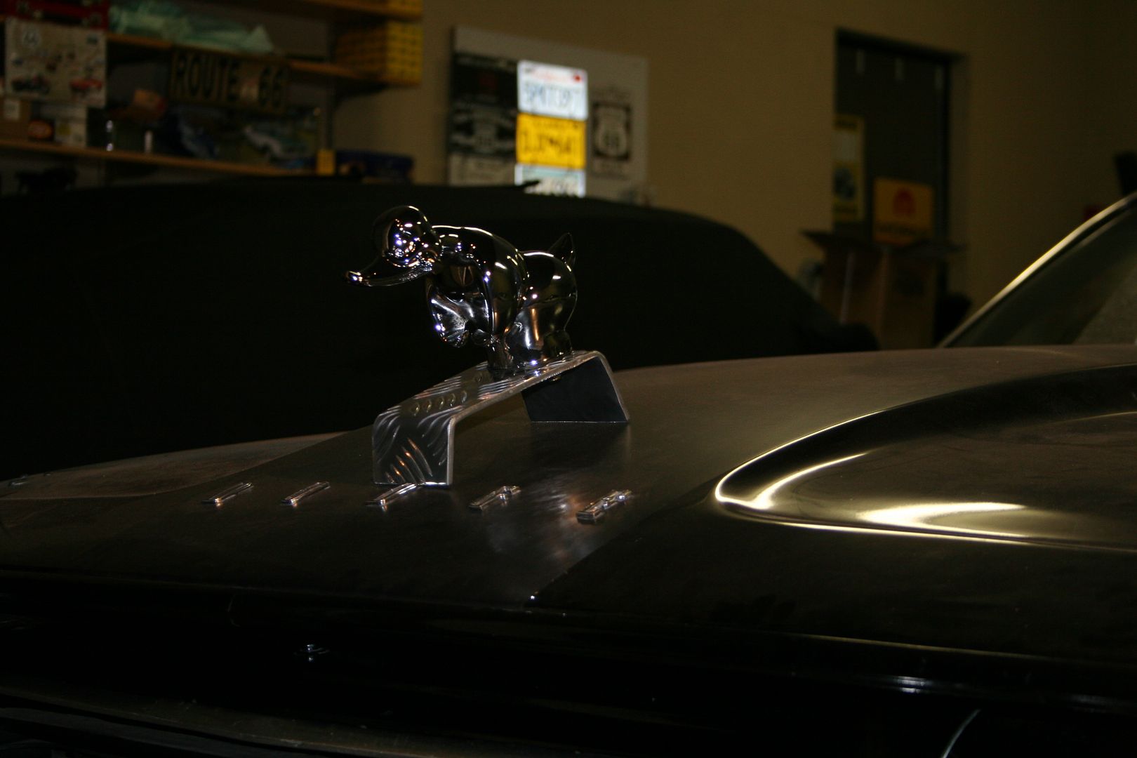 0
0 -
Well no sooner was the old girl on her wheels again & she was back up on axel stands… the brakes have never really worked on this car, no we all know that old Mopar Muscle cars are not renowned in the car world for having the best brakes anyway.. but mine always needed to be pumped when using & bleed every few weeks.. so I decided to everything.. so you’ve already seen new lines go on & a new master cylinder in the engine bay, so the last bits to install where the rear cylinders in the drums…
I’ve never really liked working on drum brakes, I’ve always found that at least one spring will try & make a break for freedom during either the dismantle or the reassembly process… but I’ve had them apart so often now in the last few weeks on this car that I now feel that I could do it blindfolded in much the same way as marines are trained to assemble there weapons… shame that this new skill of mine won’t be any use when my new disks finally turn up… anyway, below is the offending part that needed to be removed…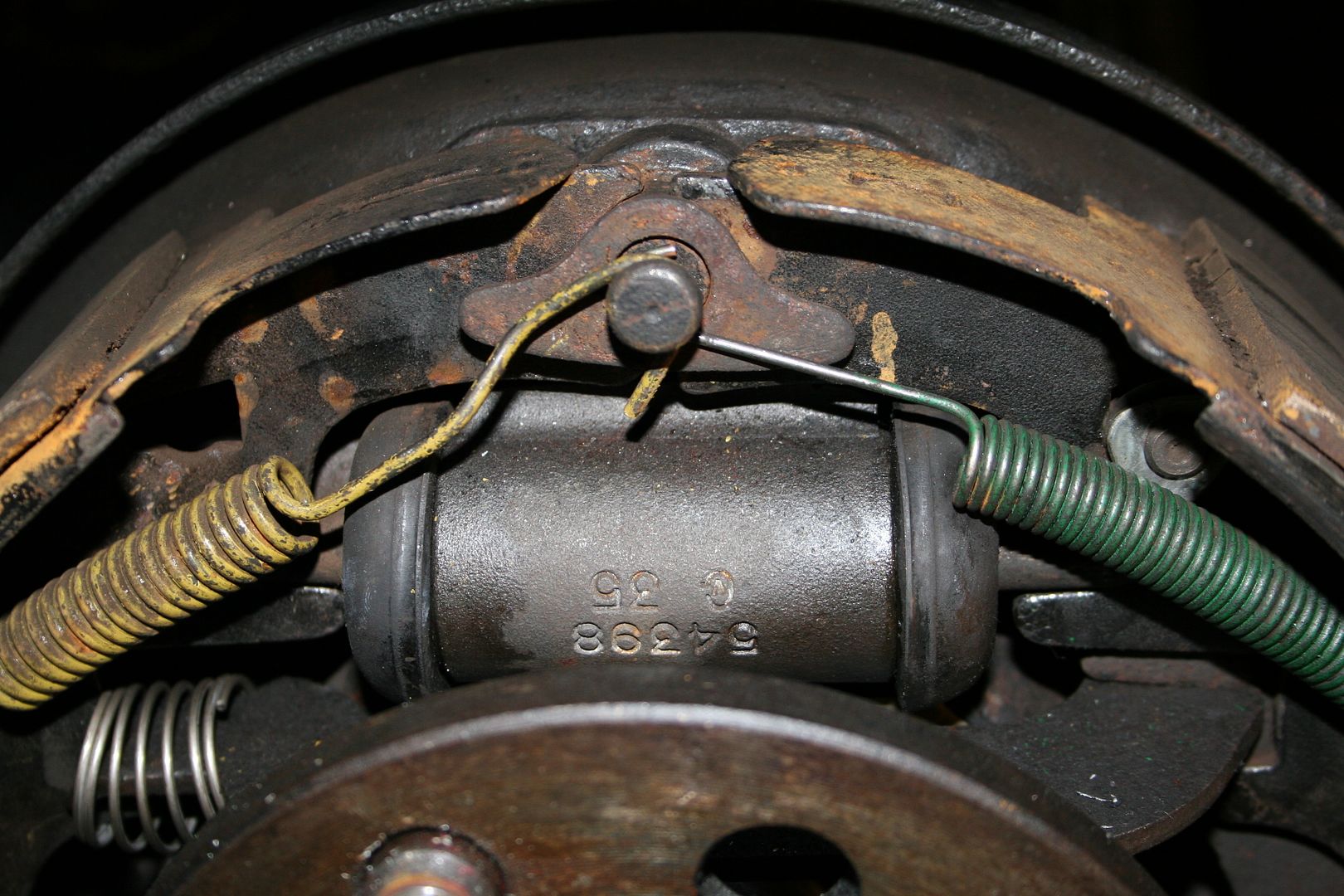
Once you have the shoes off the drums the cylinders are held n by two small bolts at the back of the drum & of course by the metal hard line that runs along the diff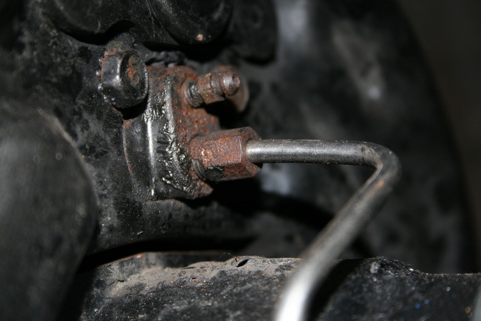
Once the drivers side was off you can see where the internal seals are shot & the fluid was weeping past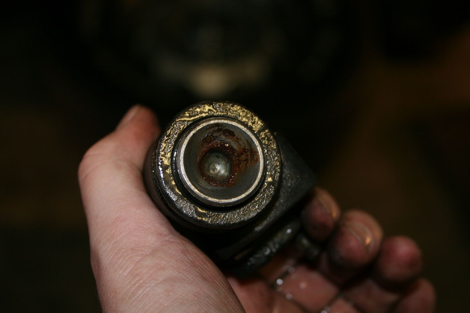
The passenger side was even worse
Old vs new part shot

New cylinder bolted back in & line hooked up

Then reinstall the shoes & all the springs & crap that holds everything together
The last thing that needed to be done to the rear end then was a final tighten up of all of the newly installed suspension bits… the destructions that came with the kit give the final torque settings as one that must be applied when the cars weight is on the wheels…. I guess they imagine that your car is on a 4 post hoist whilst your doing this… I don’t have one of them yet, so I simply put the wheels back on & then put her on a set of ramps.. same out come I guess.. then I slid back under to tighten everything up for the final time… hopefully this is the last time I’m under the arse of this car for a while now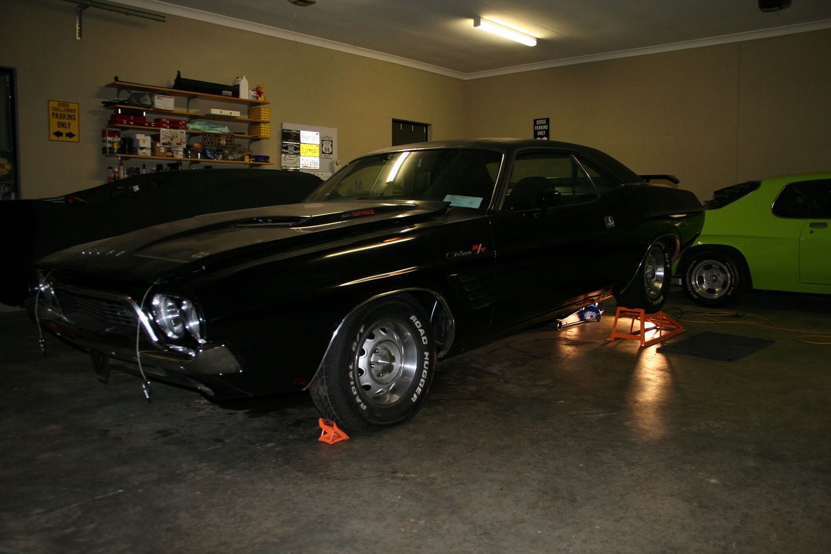 0
0 -
After I had replaced the fuel line with braided hose a few weeks ago I had decided that I would replace all the hoses in the engine bay as some of them where starting to look a bit old & some slight cracks & nicks where in them all.. so I decided to play with braided hoses again… I swear this is the automotive equivalent of working with leaches… I have never lost some much blood from a thousand tiny stab wounds as I did working with this stuff… the hundreds of needle ends on each one are lethal…
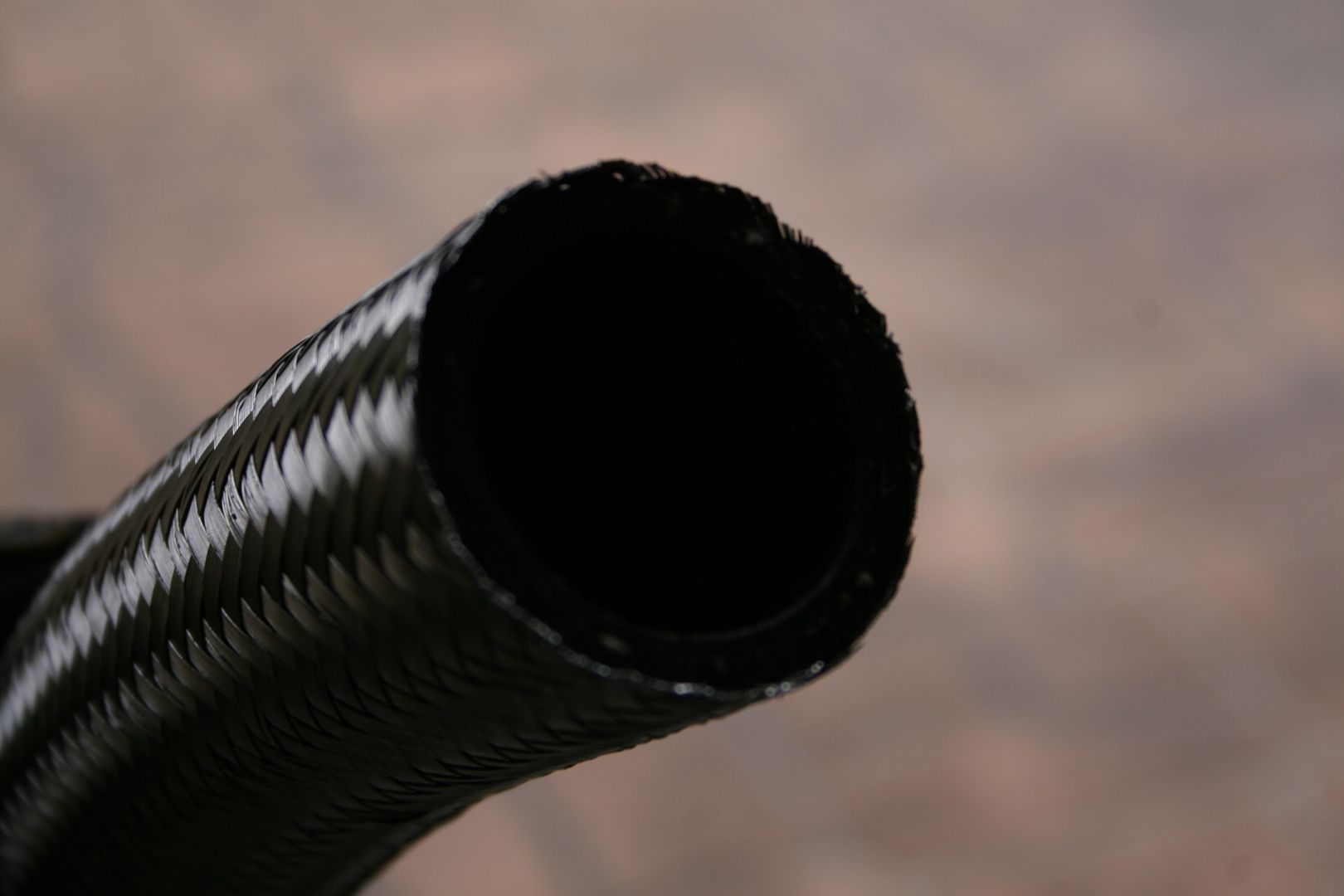
So this is how it looked before I started..
& this is how it ended up when I finished… 1
1 -
Then I decided to move my attention to some interior jobs that needed to be done, first on my list was to replace the front two piece seat belts with new Australian ADR approved three point belts. The design of the original belts if you’ve seen them is that you have a lap belt that you do up


Nothing strange there, then the second part of the belt is the optional shoulder strap that lives up on the roof when not in use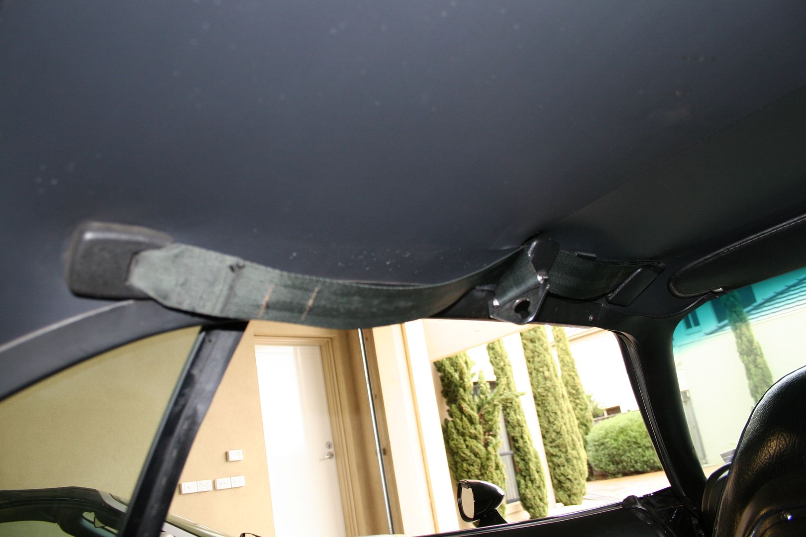
Once you have the lap belt on you undo the top belt & it clips onto the lap belt like so…
I think I’ll actually miss that part of belting up in the car, it was an unusual step but I always loved the metal click sound that it made & you hooked the two part together… anyway, first thing now was to remove the old belts… so I unbolted the stalk…. New vs old stalk shot below…
New stalk installed with all new bolts from the kit too.. I do like the chrome look..
Next step was to unbolt the shoulder section of the belt from the roof, being very careful not to twist the roof lining with the bolt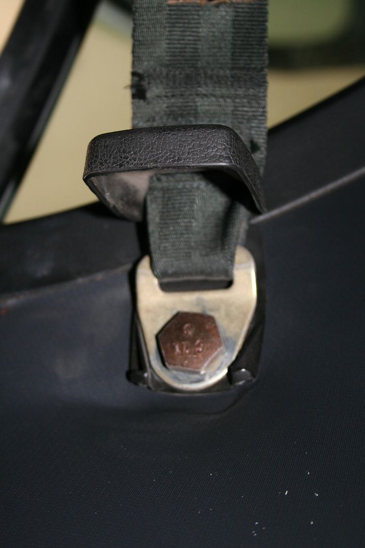
Then unbolt the floor mounted retractable reel
I was intrigued to find two wires running to this… I know that this will be for a dash light that glows red if you don’t have the belts on… but my dash doesn’t have one & it doesn’t have an empty space where one lived either… so I guess it must have been wired into every car but the dash light must have been optional??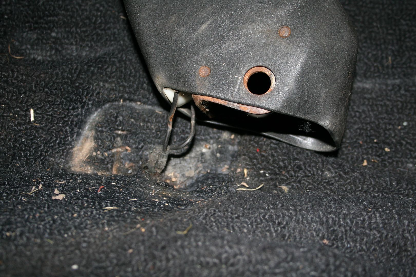
Old kit removed 0
0 -
New reel bolted in
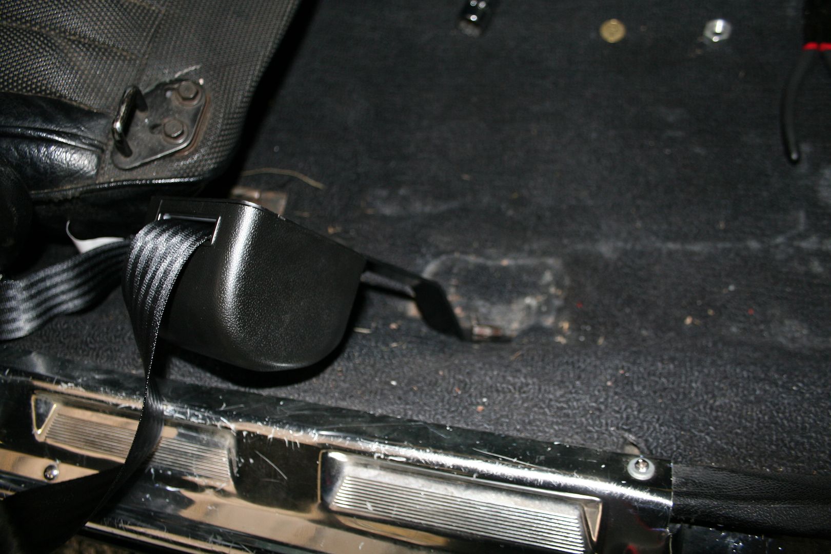

Third pointed bolted up into the roof

This is how it looks from outside now as there is now a permanent hanging drop
I couldn’t take a selfie shot with me strapped in as I was on my own in the garage.. so here is a pic of belt done up
I’m happy to say that the end of this project is really in sight now… the list of jobs to do is getting very short now… there are some lights to do, the dash has to come apart to swap some pieces over, there is a tiny weep from a bolt on the oil pan to be fixed & then she has to go & get a set of ADR approved rear seat belts fitted as the lap only rears won’t do I’m told sadly… & as that needs some plates welded in it is again out of my range of crappy skills so she’ll be going somewhere for that & then hopefully engineer sign off & on the road…. I can almost smell the unburnt fuel dribbling from here exhaust now…
Oh & I of course need to set up the front suspension as it must be miles out of whack now… but I have bought a new toy for just that little job… 0
0 -
Not much of an update but a bit more progress has been made, you may remember that due to some past mechanical muppetry the bolts that hold the brake callipers on where buggered.. one so badly that it needed a quarter inch of washers to even seat up in the hole.. I went to my local bolt place & decided to replace all 4 bolts..

I wasn’t happy with just how close the bolts sat next to where the brake lines enter the callipers so I opted for round headed nuts with hex head centres
I think it’s a much neater setup this way 0
0 -
The next step was to use my shiny new Camber/Castor tool to set up the new front end… I refused to pay the sort of cash people where asking for a set of swivel plates as a couple of hundred dollars for two plates of steel seemed like madness to me… so I figured I’d make a set, after all how hard could it be..
So I got a sheet of checker plate & a sheet of Teflon.. cut them into 4 squares & then glued the Teflon to the smooth side of the checker plate
Once this was done, then I simply put some grease on the Teflon side of one plate & sat the other plate on top… & what do you know… it makes a great swivel plate..
Gently role the car onto the plates & they slip apart… so push it off again & then push back on even gentler… & they work a treat
The destructions for setting the Caster say to swing the wheels thru 15 degrees left & then right to give a total sweep of 30 degrees, so as my swivel plates don’t have a built in angle gauge (the only reason you would spend the sill money on a set in my mind) I went for the simple approach of using a straight edge & a protractor to mark out 15 degrees left & 15 degrees right on the garage floor.. this way all I had to do was turn the wheel each time to the markings & that was the 30 degree sweep
Now checking the Camber is a simple task, just calibrate the acculevel tool to the garage floor so it understands exactly what level actually is… then attach the gauge to the rim & read the Camber measurement off the gauge… now sadly the Caster & Camber adjustments for the front suspension interfere with each other… so you can’t just set one & then then set the other & then be done… once you set one, you set the other, then you check & in my case reset the first one again… etc..
Setting the Caster is a bit more involved that the simple camber adjustment.. if we focus on the drivers side (left hand side) wheel…. firstly to read the actual Caster angle you turn the wheel 15 degrees to the left & then activate the Caster mode on the gauge & zero the reading
Then you swing the wheel back to straight & then continue through to 15 degrees to the right to give the full sweep of 30 degrees (note other tools may ask for more or less of a sweep angle, but my tool is calibrated for a total sweep of 30) Then you simply read the caster angle off the gauge… recording if it’s Positive or Negative of course
To adjust the Caster angle you have to back off the nut that locks the lower strut arm to the lower control arm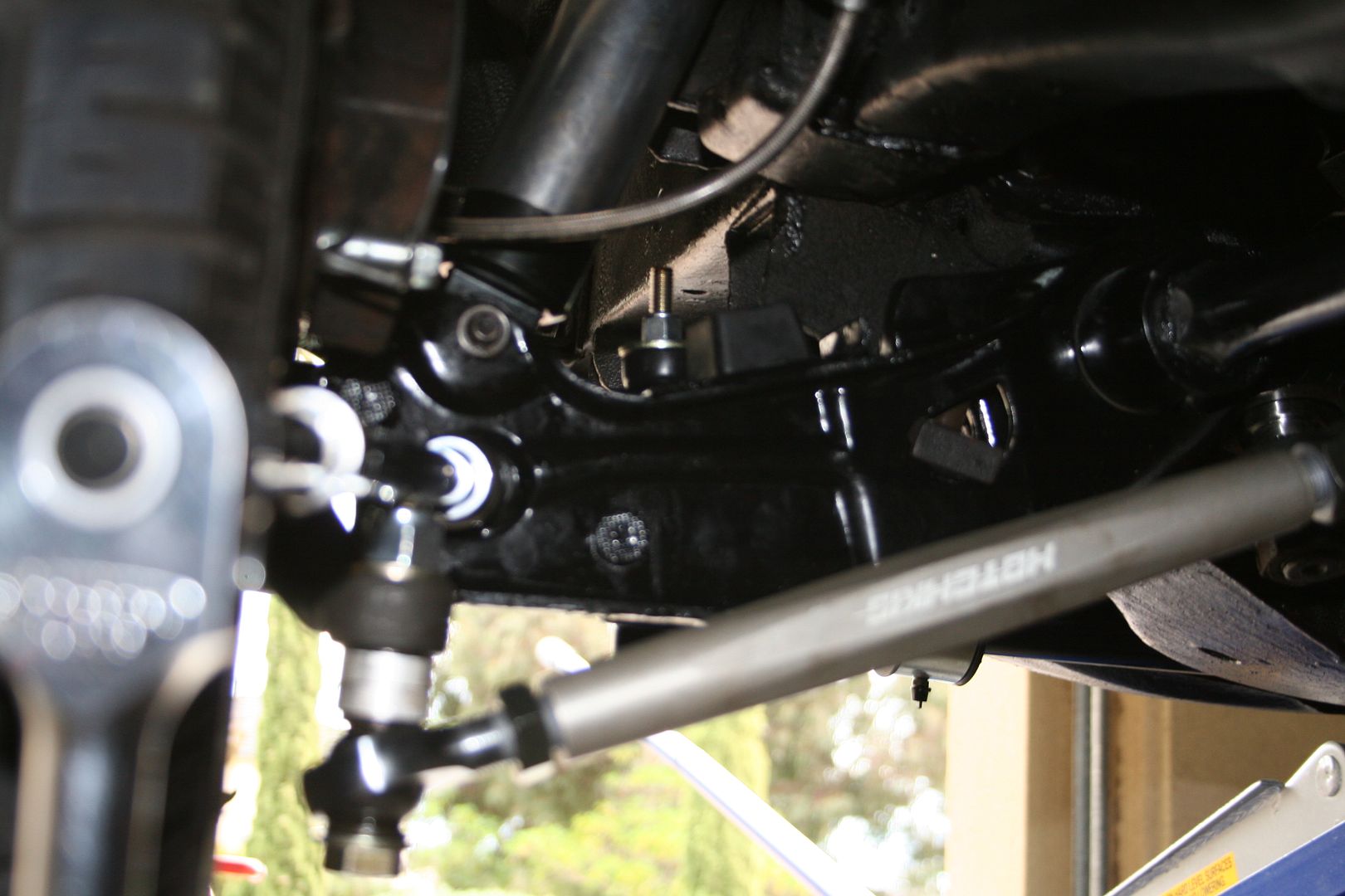
Then using something to protect the nice powder coated paint surface you wind the rod either in or out depending on what your reading was… I was chasing a Positive Caster angle of 5 degrees BTW…
Now some feedback that I would have for the nice folks at Hotchkis is that they should have designed two flat sides into a small section of that strut rod as that would have made turning it without damaging the surface a much much better experience..0 -
Time for an update, yet again work has prevented me from spending as much time working out in the garage as I would have liked over the last few weeks.. but some progress is still being made..
First on the list for me to fix was the broken & crapply painted front indicator lenses.. I had bought a new set ages ago but just never got around to fitting them, I’ll be replacing them with a clear set at some point but for now I was happy to get rid of the crappy old ones that you couldn’t really see thru anymore & where badly hand painted in the past..
New vs old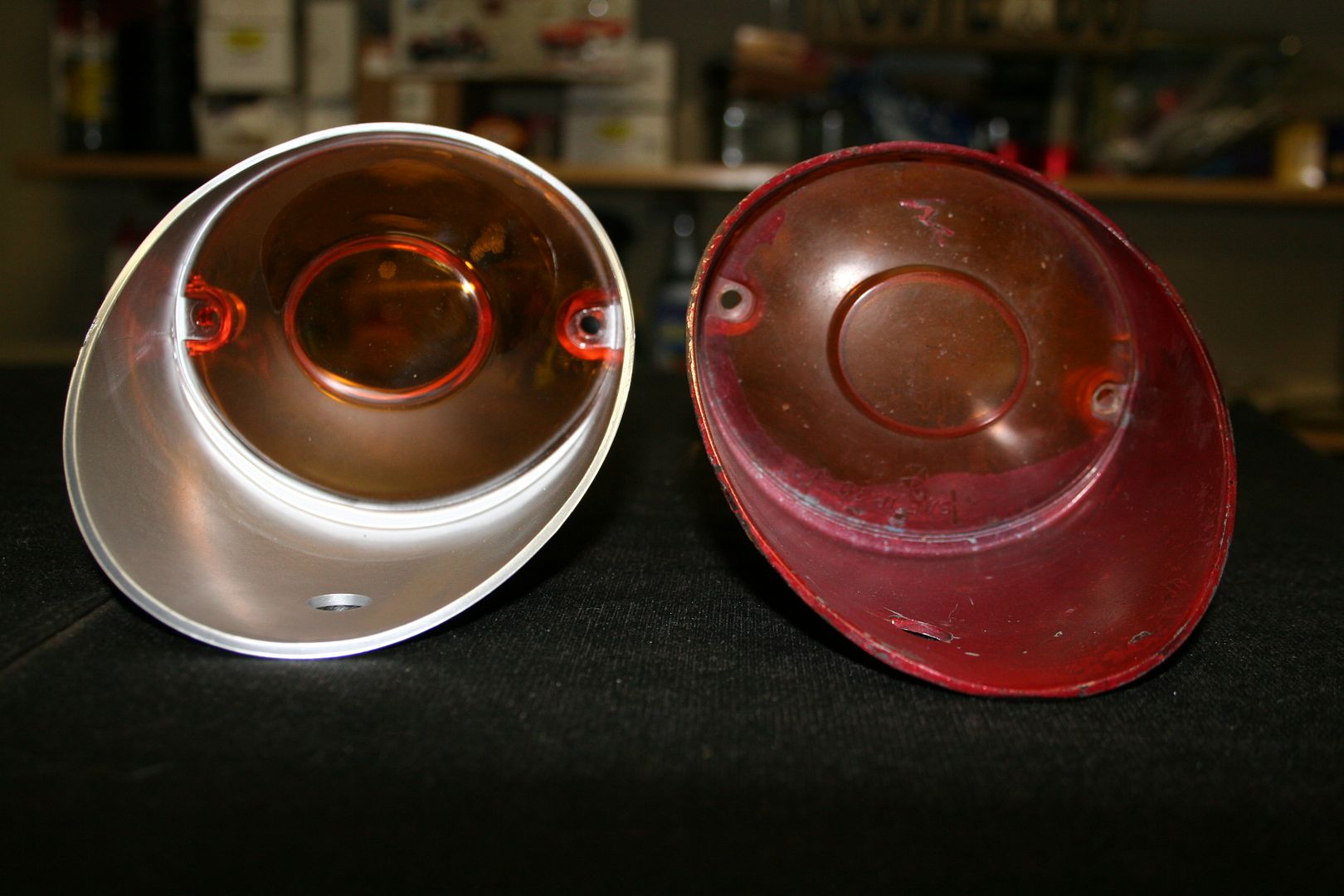

Now when you remove the light housing form the car you notice that they are clearly marked as left & right & you also notice that the holes that the holding screws use are offset, again because they are different for left & right fitment… well some previous owner has made another entry into my why Muppets should be allowed to work on cars book that I’ll be writing at the end of this project… they put them in the wrong way around.. now rather than see the big L & R on them & rather than trying them on the other side they proceeded to bend the bloody brackets that hold them in place… so now when I tried to fit them to the correct sides I end up with this sort of seamless fitment
Now I resisted the urge to put them back in the wrong sides, so I spend a while bending brackets in an attempt to get them to fit somewhat well… they are not 100%, far from it… but they are close enough for now.. the front & rear valance panels are badly damaged on this car anyway, so when the respray & roof removal happen next year I’ll fit new panels then…

Next thing to work on was adjusting the new steering box, you will recall that I fitted a new box the other week, well I fired the car up the other day for the first time since & she was in the air on axle stands at the time as I was greasing all the nipples under the car… anyway when she fired up it swung to full left lock all on its own… & if I turned the wheel to full right lock & let go it would swing back full left lock.. so out came the manuals again.. it seems that the location of the valve body on top on the steering box effects what Dodge call self-steer.. the whole valve body must be tapped up the steering box to remove left hand self-steer & down the box to remove right hand self-steer.. now when I say move we’re only talking mm’s here.
So you crack the two nuts that secure the valve body to the steering box, I’m pointing to one with the screw driver here
Then you very gently tap the valve body either up or down.. in my case up.. the manual says to tap on the bolt on the face of the valve body, I’m pointing to it with the screw driver here
It took a tap of I would say 1.5mm max & the steering is spot on now, no more pull to one side or the other…. Job done0 -
Next on the list of things to fix was the headlight switch in the dash, at some point in the cars past the switch died & would only turn on the side lights, the second circuit that powered the main headlights no longer worked… so a previous owner decided not to repair that but to bypass it by fitting a new toggle switch under the dash behind the aftermarket gauge cluster… now obviously that wasn’t going to get past a roadworthy inspection here so I found a NOS headlight switch on the interweb to do the repair properly..

So now I had to do one of the jobs that I hate on old cars… I had to pull the dash apart.. I hate doing this on old cars as after decades the parts & connectors get very brittle & you never know what sort of mess you will find behind there & given the level of past workmanship this car has had I didn’t have high expectations I can tell ya..
First step was to unbolt the steering column saddle to allow the wheel & column to drop down out of the way to give me the maximum wiggle room required to get the dash apart
Then I had to undo the 6 screws that hold the dash light panel onto the crashpad, once that’s levelled down you can flip it over & rest it onto of the dash, the wiring is long enough to allow for that


Once that was out of the way I could then see the top screws that hold the switch panel & the gauge panel in place.. the switch panel has to come out first
Once the screws are undone the switch panel can be carefully wiggled out of place & there is just enough play in the wiring to let it hand down enough for you to get your fingers in behind to unhook the connectors
 0
0 -
Now when I went to undo the connector for the windscreen wipers/washers I found that the connector had been cable tied together by someone

Why had the connector been cable tied I hear you ask… well because the connector clearly has a short that is causing the plastic to melt!!!!!! Now did they fix the problem as clearly that much heat in the wiring behind the dash is not a good thing… no they cable tied it together as clearly the now melted connecter was not holding on well enough.. I swear some of the work done on this car is a crime.. & all I can say is this, for whom ever is responsible for this… may a hive of flesh eating termites infest your rectum
Switch panel out
New headlight switch vs old
New headlight switch installed
Then I had to remove the toggle switch that had been installed & trace it’s wiring back to find where they cut the original so I could repair that to allow the new switch to work
I love the way the wiring has been altered on this car, I really love how they clearly didn’t have any new wires to use so they just connected together odd lengths of wire to make up what they needed… & no I’m not making this up… the wires change colour & gauge on this car… so if someone is in the car tracing the 5mm red wire.. that can become the 3mm black wire & then the orange wire before it reaches it end point in the engine bay!!!
Once I traced the wires it was at the high beam switch in the foot well that they spliced in to get the feed to their toggle switch.. oh & do we use terminals or solder or connector blocks… no just twist the wires together & run a bit of tape over them…. That’s the way…
Once I’d removed all that crap, I resoldered the original wires together & tested the new switch… works a treat… job done.0 -
Advertisement

Advertisement