Advertisement
If you have a new account but are having problems posting or verifying your account, please email us on hello@boards.ie for help. Thanks :)
Hello all! Please ensure that you are posting a new thread or question in the appropriate forum. The Feedback forum is overwhelmed with questions that are having to be moved elsewhere. If you need help to verify your account contact hello@boards.ie
Hi all! We have been experiencing an issue on site where threads have been missing the latest postings. The platform host Vanilla are working on this issue. A workaround that has been used by some is to navigate back from 1 to 10+ pages to re-sync the thread and this will then show the latest posts. Thanks, Mike.
Hi there,
There is an issue with role permissions that is being worked on at the moment.
If you are having trouble with access or permissions on regional forums please post here to get access: https://www.boards.ie/discussion/2058365403/you-do-not-have-permission-for-that#latest

Ford Transit conversion to camper MKII

1235710

Comments

  • Registered Users, Registered Users 2 Posts: 6,260 ✭✭✭Buford T Justice


    Should I fuse the 2 +ives and the -agtive?


  • Posts: 5,238 ✭✭✭ [Deleted User]


    Yurp


  • Registered Users, Registered Users 2 Posts: 6,260 ✭✭✭Buford T Justice


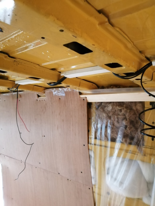
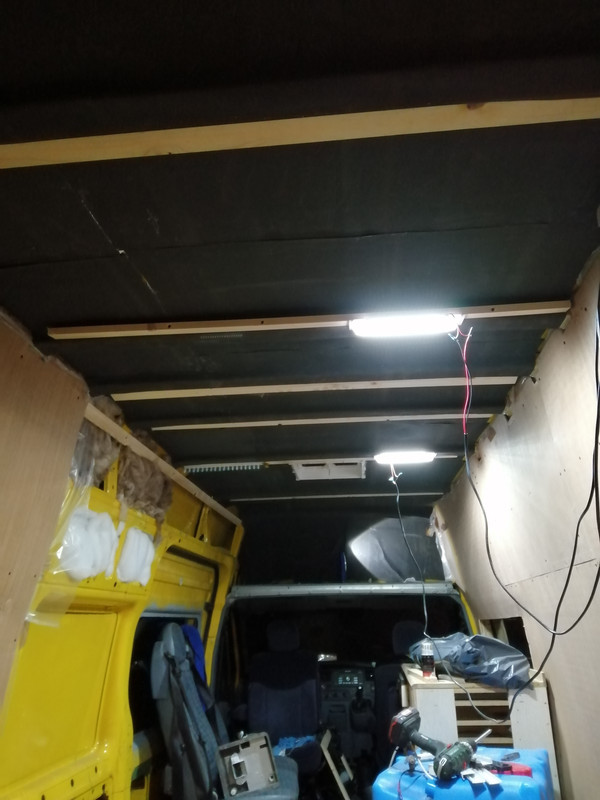
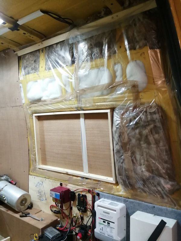
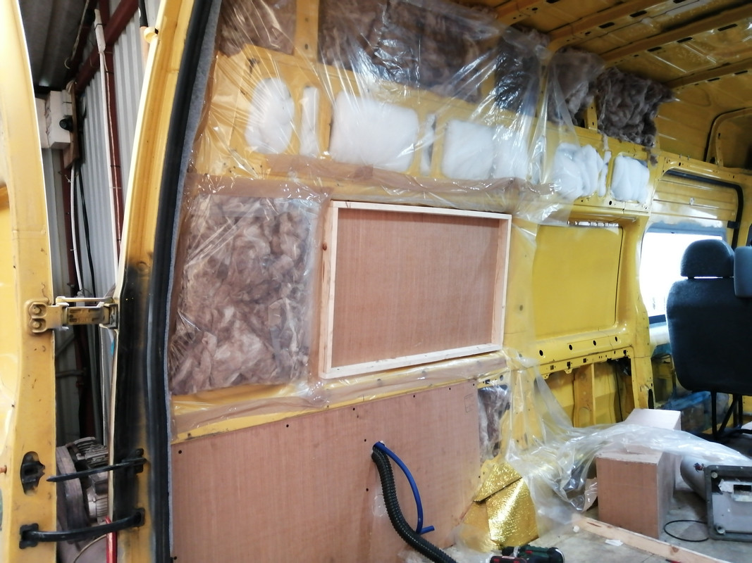
    I removed all the panels on the side of the van again, partly because i needed to re-seat the power cable due to the cassette going out thorough the side of the van. I also ran a length of 2x1 from the front to the back of the van at the top which you can see below.
    It gives better places to mount things to, and avoids the severe bend out a the top of the van.

    I also put the batons that I had between the two panels on the outside of the vapour barrier and sealed up the holes that were made. I also tidied around the sides of the panels where the plastic was just ..... hanging around.

    I've also run some cable in the roof, hence the conduit to hold them in place

    IMG-20210110-133913.jpg


  • Registered Users, Registered Users 2 Posts: 6,260 ✭✭✭Buford T Justice


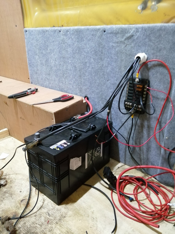
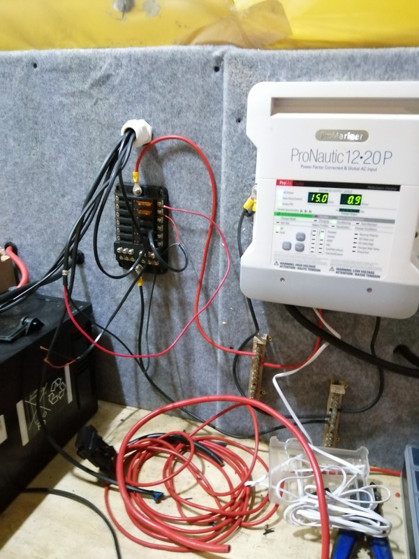
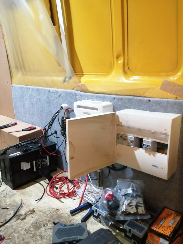
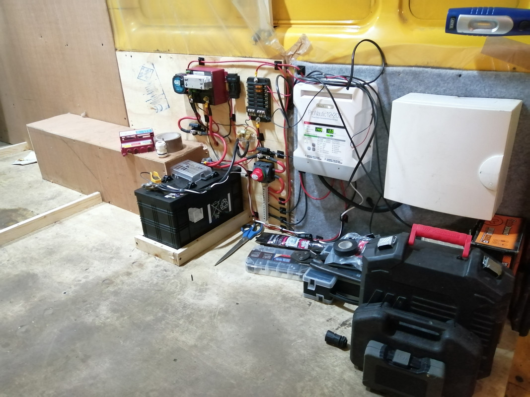
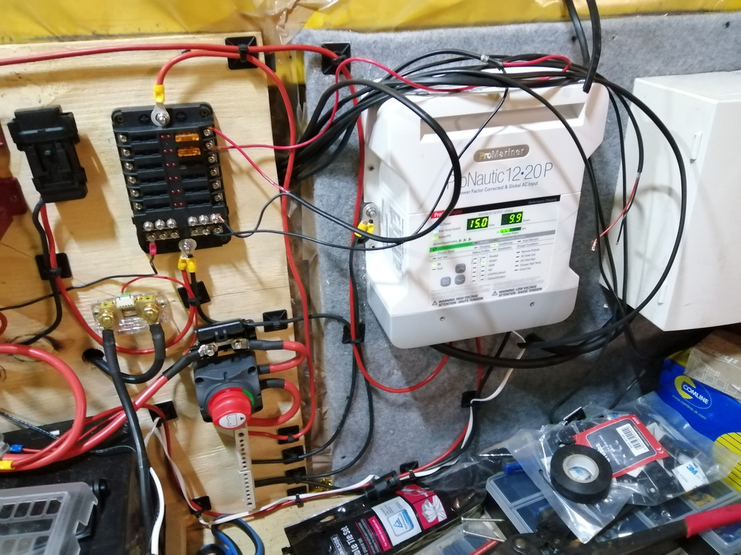
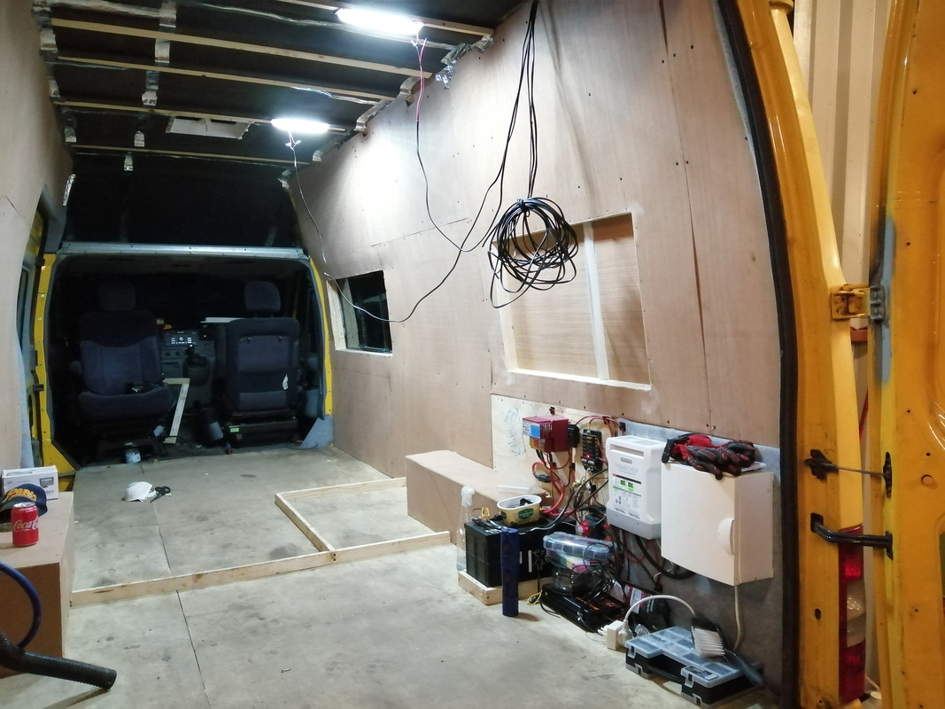
    Fitted the battery and the charger today too, along with the consumer unit

    The more astute of you will notice that I had to take a corner from the wheel arch cover since I missed checking before I drilled my holes.

    So far I've got one 110AH battery. That'll do for now.

    IMG-20210110-172340.jpg

    I've set the charger to power supply for now and wired the output to the +bus bar. The batter hasn't been connected yet since i don't have any fuses or holders, I'm waiting them to arrive.
    In thinking about this, I also have an isolator to fit so I'm most likely going to go direct to the battery with the charger & run from the battery to the isolator & switch to charge. I've also wired up some lights in the van temporarily, since y'now darkness

    IMG-20210110-172332.jpg

    Consumer Unit

    IMG-20210110-172346.jpg


    Brexit has royally fucked everything up. It's impossible to get anything of amazon as practically no one is shipping to Ireland, so most of my time is spent looking at stuff that doesn't ship. I've tried .fr and .de but they're not that great. I ordered a diesel heater on .de but it's still not shipped since last thursday. I had already bought one from .fr but it was cancelled and refunded since due to covid 19, we can't ship to your city - load of bollix - they are a drop shipper who has stock in the UK.

    I've also ordered an inverter of another site, but same diff with them in regards to shipping. Sir Liamalot, the conversation with that guy dropped off a cliff. Had a deal done and he just stopped responding to me.

    May have to go back to .co.uk and use address pal. That's fine for something that's a few quid, but when I"m looking for consumables like a roll of wire or crimp connectors and stuff it becomes prohibitively expensive.

    £2 odd for a bag of connectors with £9.99 shipping. Its ridiculous.


  • Registered Users, Registered Users 2 Posts: 73,477 ✭✭✭✭colm_mcm


    Big progress there!


    How did your leak work out?


  • Registered Users, Registered Users 2 Posts: 6,260 ✭✭✭Buford T Justice


    colm_mcm wrote: »
    Big progress there!


    How did your leak work out?

    Took the window out again and re-sealed it without the rubber seal around the metal edge.

    In terms of the roof, I don't believe the skylight is still leaking now, but not 100% convinced. Given the weather the roof of the van is riddled with condensation - you can actually see it some of my previous photos. Every time I move it there's a rainfall inside. That said, after the last bout of bad rain there was no water inside like there was when it was first noticed the leak.

    I have 25mm kingspan for the roof and I'll have to wait for better weather to do it, plus I'm not ready yet. Not forgetting the seam seals on the roof will all be re-done too, in better weather


  • Posts: 5,238 ✭✭✭ [Deleted User]


    Brexit has royally fucked everything up. It's impossible to get anything


    Addresspal are +20% tax

    +€4.50 handling charge.


    Talk about shooting yerself in the foot. :rolleyes:
    I'm not buying anything else until Sterling is £1.50 to the €. Gobshytes!
    We're almost as bad, running around putting band-aids on things. Where's addresspal France?


    If you buy from NI it's duty free to the Irish. In a coupla years that'll be the backdoor to Europe...Farcy Macb0ll0x...


    The isolator oughta turn off the loads but bypass the chargers.
    Albright make switch-disconnect ones that don't set fire when they break 100% rated load.


    Most of the mickey mouse ones are no-load operation only.


  • Registered Users, Registered Users 2 Posts: 6,260 ✭✭✭Buford T Justice


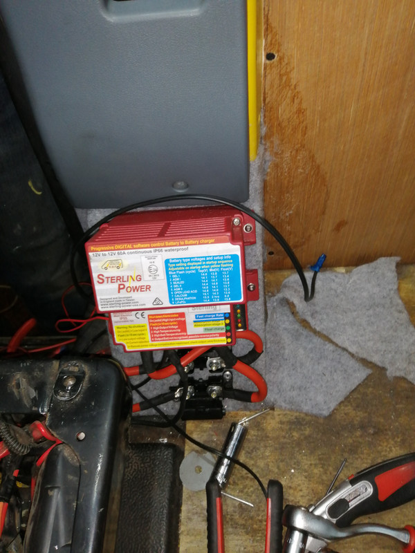
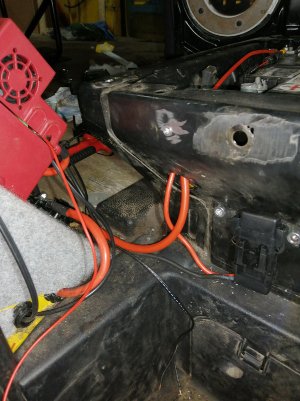
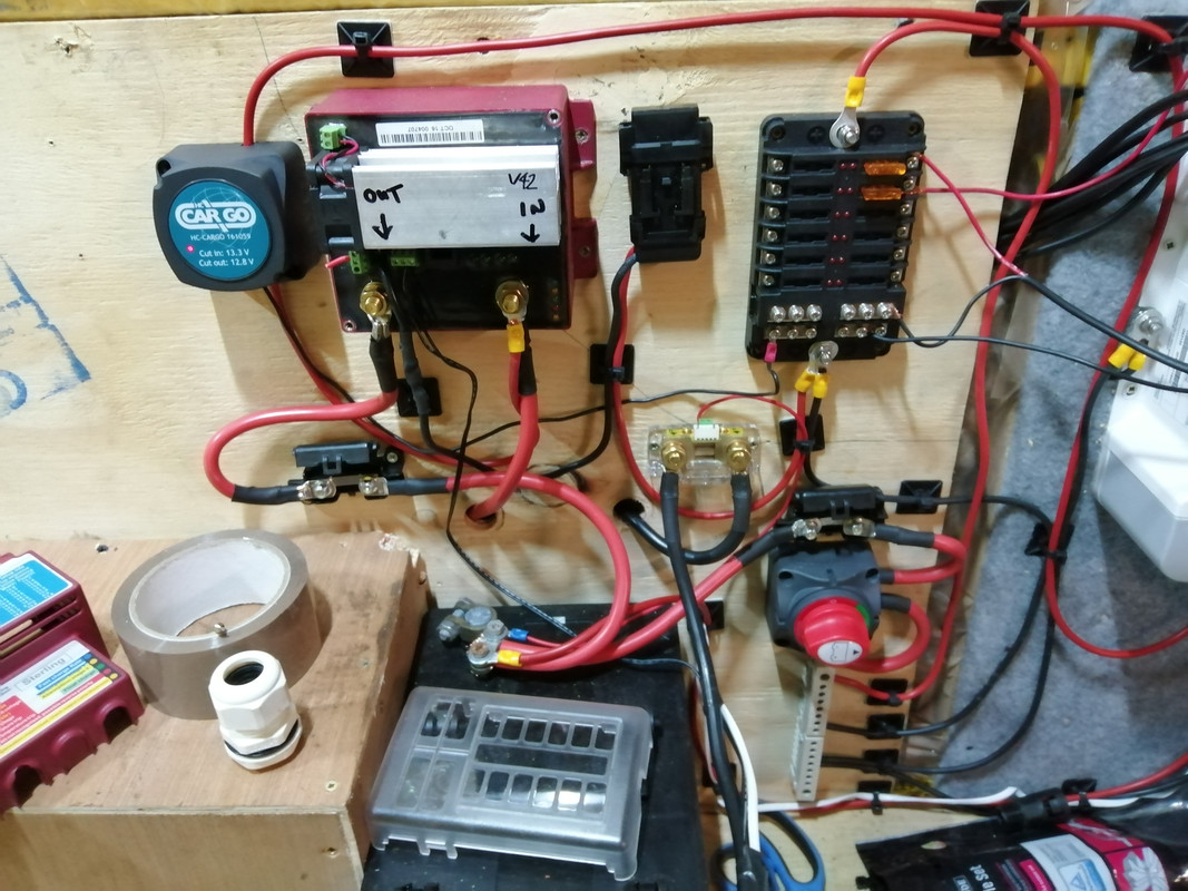
    Had a stab at fitting the b2b charger today.
    I decided I'd fit it on the side of the seat, so it'd be beside the batteries and all that. I needed a bracket to support the bottom of it so I made one up, welded & fitted it. Had it installed and then I realised that the door wouldn't close because of the pocket - so that popoo'd that idea. Another one to chalk down


    I moved it to the bottom of the B pillar, added the fuses along with one for the negative.
    This isn't completed as yet, I have to find an ignition source for the control somewhere in the battery box if I can. Have to add the fuses and fit the temp sensor at the battery.

    IMG-20210113-215033.jpg

    IMG-20210113-215325.jpg

    IMG-20210113-214843.jpg


  • Registered Users, Registered Users 2 Posts: 34,104 ✭✭✭✭listermint


    You happy with the charger and consumer unit location? They shouldn't really be fixed to that stretch cloth. Fire hazard there. I'd review that. I'd even examine the small fuse board connection location.


  • Advertisement
  • Registered Users, Registered Users 2 Posts: 6,260 ✭✭✭Buford T Justice


    listermint wrote: »
    You happy with the charger and consumer unit location? They shouldn't really be fixed to that stretch cloth. Fire hazard there. I'd review that. I'd even examine the small fuse board connection location.

    Stretch cloth was cut out from behind the consumer unit and the charger for that very reason - can also remove it from the 12v fuseboard.


  • Posts: 5,238 ✭✭✭ [Deleted User]


    so it'd be beside the batteries and all that.


    Supposed to be beside the house battery not the engine batteries. Not that it'll make much difference on your massive cable. It's a boost regulator..whatever it gets on the input it boosts so voltage drop doesn't matter, the output ought to be as short as possible because that's the final regulation.

    The back of that unit doesn't get hot.


    How're ya gonna charge 2 engine bateries with one cable from your pronautic?


    Big bus bars down by house battery land would make everything much tidier.

    We connect the chargers and loads to the bus bar and the battery then has only one cable at the terminal (not counting little sense leads)


  • Registered Users, Registered Users 2 Posts: 6,260 ✭✭✭Buford T Justice


    Supposed to be beside the house battery not the engine batteries

    Bollox. I thought it had to be at the Front

    How're ya gonna charge 2 engine bateries with one cable from your pronautic?

    Yeah.... about that. Say I moved the charger to the back of the van and If I only want to charge the starter battery can I link the pro-nautic to the input of the sterling, or would that be a big no no?


  • Posts: 5,238 ✭✭✭ [Deleted User]


    or would that be a big no no?


    You can but it's messy and no offence, DIY not Pro.
    that sortov wiring gets messy fast and it's extremely difficult to troubleshoot after. Hence my bus bar suggestion.


    Er..but you've 2 engine batteries!?
    Best find out what they're for before we get too carried away.
    I'd be inclined to use one smartbank and two relays if your ECU won't be upset by it, in order to know that you'll have to investigate why you have 2 batts.
    If you want to "be lazy" run a third way from the Pronautic with a proviso to maybe use it for solar too in the future.


    I'd have the engine battery -> local fuse -> long run to rear -> Engine Stud/Bus at House Distro
    & House bus bar -> local distribution & fusing serving:

    • Isolating Disconnect fuseblock -> all loads
    • Pronautic + Fuse
    • Solar Charge Controller (later) + circuit breaker / fuse
    • Inverter + Fuse + Isolator
    • B2B + Fuse
    Schematics at €80 per..:p ;)


  • Registered Users, Registered Users 2 Posts: 6,260 ✭✭✭Buford T Justice


    Er..but you've 2 engine batteries!?
    Best find out what they're for before we get too carried away.

    One for starting and one for the accessories in the van, lights etc... the rear battery is the starter. If I was so inclined I could remove the second battery and have it all powered by the starter battery


  • Registered Users, Registered Users 2 Posts: 6,260 ✭✭✭Buford T Justice


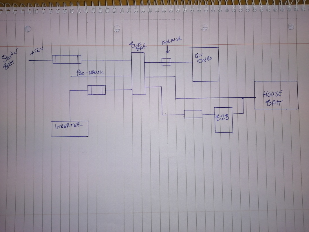
    Is this what you had in mind?

    That's supposed to be a fuse to the left of the b2b

    IMG-20210114-180948.jpg


  • Advertisement
  • Posts: 5,238 ✭✭✭ [Deleted User]


    One for starting and one for the accessories in the van, lights etc... the rear battery is the starter. If I was so inclined I could remove the second battery and have it all powered by the starter battery

    I think there's a lot more to it than that, anything official to confirm? Are they both the same voltage at all times when underway?


    Here's a few similar I did earlier..these things take days...
    Obviously not exactly what yer looking for. Every installation is different.

    539469.jpg

    539470.jpg

    539471.jpg

    539473.jpg

    539474.jpg


  • Posts: 5,238 ✭✭✭ [Deleted User]


    Is this what you had in mind?


    The B2B has input and output linked.

    In = engine battery post/bus

    Out = house battery bus


  • Registered Users, Registered Users 2 Posts: 6,260 ✭✭✭Buford T Justice


    Yes. Split charge relay joins the two batteries together in parallel when the ignition is turned on. Prevents the radio / lights from running the starter battery dead.


  • Posts: 5,238 ✭✭✭ [Deleted User]


    Yes. Split charge relay joins the two batteries together in parallel when the ignition is turned on. Prevents the radio / lights from running the starter battery dead.


    Is that an OE split charge relay?


  • Registered Users, Registered Users 2 Posts: 6,260 ✭✭✭Buford T Justice


    Is that an OE split charge relay?

    Yes - Factory fit


  • Advertisement
  • Registered Users, Registered Users 2 Posts: 6,260 ✭✭✭Buford T Justice


    Moved some things around....

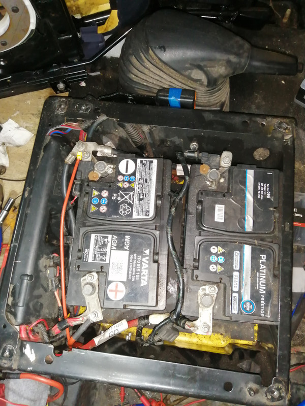
    There is a fuse at the seat base beside the starter battery.


    IMG-20210114-222025.jpg

    I want to see if I can get a better bus bar for the power feed. What I plan to do is put the isolator from the battery feed to the bus bar, and have the b2b and pro-nautic feed into the bus bar. That way they can charge the battery and I can isolate the power into the van when I need to. I can also isolate the batter and use the pronautic as a power supply if it suits me.

    Don't mind the terminals that are on the battery there - they're just there to run the lights for now

    WRT to charging the starter batter from the pronautic. I have a split charge relay lying around that I no longer need. I was thinking I could put that between the pro-nautic and the input on the sterling. This will allow the charger to supply the battery when shore power is in, but when on the road the battery will be isolated from the pro-nautic.

    Thoughts?


  • Posts: 5,238 ✭✭✭ [Deleted User]


    Yes - Factory fit


    Pardon my scepticism but it's highly suspicious Ford added 10kg of high tech lead, and split charge for such a whimsical reason. Vehicle manufacturers (especially Ford) don't spend money they don't have to.


    It could be regen and the accessory battery is being deep-cycled with the engine battery on charge only.


    Regen is a moving target, you have to record the system in normal operation (or rtfm) over the course of urban driving to ascertain what it's doing. Sticking a multi-meter onit once and saying she's right isn't thorough enough.


    ....if it is as you say then one battery/standard split charge is fine. If it's more sinister I can't make a recommendation until I know what it is and doing but it the absence of that the ProNautic outputs are isolated so you won't go wrong running one per battery (4mm² is loads, 6mm² if you want a sufficiency of overkill).


    If you run the Charger outputs now you can intercept them and rearrange their functionality down the line from the house battery distribution.


    Moved some things around....


    :pac: I often say amateurs get it right the second time...Pros do it 4 times!


    There is a fuse at the seat base beside the starter battery.


    Good place for it, closer the battery the better. Terminal fuses are deadly...no holder required...they only work on threads though...and they can heat the battery if you're like me and push them to the limits. ....I've never met someone like me...most people can't pull 300A off a battery system...I'm sure they're out there though.


    I want to see if I can get a better bus bar for the power feed.


    c9e351f7c9b2113cb915dba630707ba834d26a08_original.jpeg
    What I plan to do is put the isolator from the battery feed to the bus bar, and have the b2b and pro-nautic feed into the bus bar.


    Engine battery (B2) to engine Battery bus.
    B2 bus -> B2B in & ProNautic Out


    That way they can charge the battery and I can isolate the power into the van when I need to.


    Both of those units are automatically self-isolating


    I can also isolate the batter and use the pronautic as a power supply if it suits me.


    Better to not isolate chargers. It can damage solar controllers and usually, you want the chargers to have independent isolators for servicing. For storage and troubleshooting you usually want chargers on and loads off.


    The ProNautic will act as a power supply regardless. It has load compensation. The feature just means that if you take the battery out of the van then the 12v can still work from mains.


    Don't mind the terminals that are on the battery there - they're just there to run the lights for now


    Seen worse as a permanent fixing. :pac:


    WRT to charging the starter battery from the pronautic. I have a split charge relay lying around that I no longer need. I was thinking I could put that between the pro-nautic and the input on the sterling.


    This will allow the charger to supply the battery when shore power is in, but when on the road the battery will be isolated from the pro-nautic.


    The 3 outputs on that charger are isolated. You're making it complicated.


    Thoughts?

    I've always wondered why Sterling made the Out the first stud and In the second. :confused:
    Looks like a c0ck-up they decided nobody'd notice.

    Put a screw through the cable tie mounts, the sticky back is just for placement.

    Why did you fuse the ground? What size is the fuse?
    I don't like yer battery terminals.


    s-l400.jpg

    I don't like yer battery isolator either. I use contactors or albright EDs


    The stud on the side of the pronautic is an earth (green) not a ground (black).


    No harm in what you've done...in fact, it's correct to earth the ground but you're confusing the function of the conductor and your ground bus ought to be connected to the earth bus and the inverter neutralised with it's own earth leakage protection making it TN-S.


    Why is there a terminal strip under the ProNautic?
    You can use the one on the fuse block.


    You need a set of these for the big loads:


    s-l500.jpg


  • Registered Users, Registered Users 2 Posts: 6,260 ✭✭✭Buford T Justice


    Pardon my scepticism but it's highly suspicious Ford added 10kg of high tech lead, and split charge for such a whimsical reason. Vehicle manufacturers (especially Ford) don't spend money they don't have to.

    https://fordtransit.org/forum/viewtopic.php?f=5&t=135949
    https://www.motorhomefun.co.uk/forum/threads/ford-transit-under-cab-seat-twin-batteries.215433/post-3769064

    This is what I know. I don't know any other reason for it.


    The 3 outputs on that charger are isolated. You're making it complicated.


    One output to go to the house battery, another to the starter battery


    Put a screw through the cable tie mounts, the sticky back is just for placement.
    already ahead of you on that one :pac::pac::pac:
    Why did you fuse the ground? What size is the fuse?
    Because you said to. 30A


    I don't like yer battery terminals.


    s-l400.jpg

    They're better alright


    Why is there a terminal strip under the ProNautic?
    You can use the one on the fuse block.

    Just a negative bus bar, that's all


  • Posts: 5,238 ✭✭✭ [Deleted User]


    This is what I know. I don't know any other reason for it.


    I'm gonna file that under, not doing yer homework fer ya. :pac:
    If it's that primitive and overengineered sure one cable/battery will do.
    You can use the feeder for the B2B to double as the charge from ProNautic.


    One output to go to the house battery, another to the starter battery


    Grand so.


    I'll take it that that black cable floating in the breeze with the wall-mounted Mega Fuse is actually a positive then? Grand. I double my rates when I'm asked to work on installations with that craic.


    They're better alright


    Much. Better clamping, post for temp sensors and sense cables. You need a cable mounted insulator for the +ives though.


    Just a negative bus bar, that's all


    Yes, you have two a foot apart.


  • Registered Users, Registered Users 2 Posts: 6,260 ✭✭✭Buford T Justice


    I'll take it that that black cable floating in the breeze with the wall-mounted Mega Fuse is actually a positive then? Grand. I double my rates when I'm asked to work on installations with that craic.

    No. Its a fused negative for the b2b. I was re-using the a maxi fuse that I had, and I had no additional black cable to swap out at the time. The red from the maxi fuse will be replaced with black.


  • Posts: 5,238 ✭✭✭ [Deleted User]


    S9ctNg6.jpg

    That one


  • Registered Users, Registered Users 2 Posts: 6,260 ✭✭✭Buford T Justice


    That one

    That's the terminal for the battery monitor, going to the neg of the batter and then GND


  • Posts: 5,238 ✭✭✭ [Deleted User]


    Ah very good. That meter's amazing value. I have two, both worked outtov the box. I've spent days calibrating or failing to calibrate ones 4-5 times the cost.


  • Registered Users, Registered Users 2 Posts: 6,260 ✭✭✭Buford T Justice


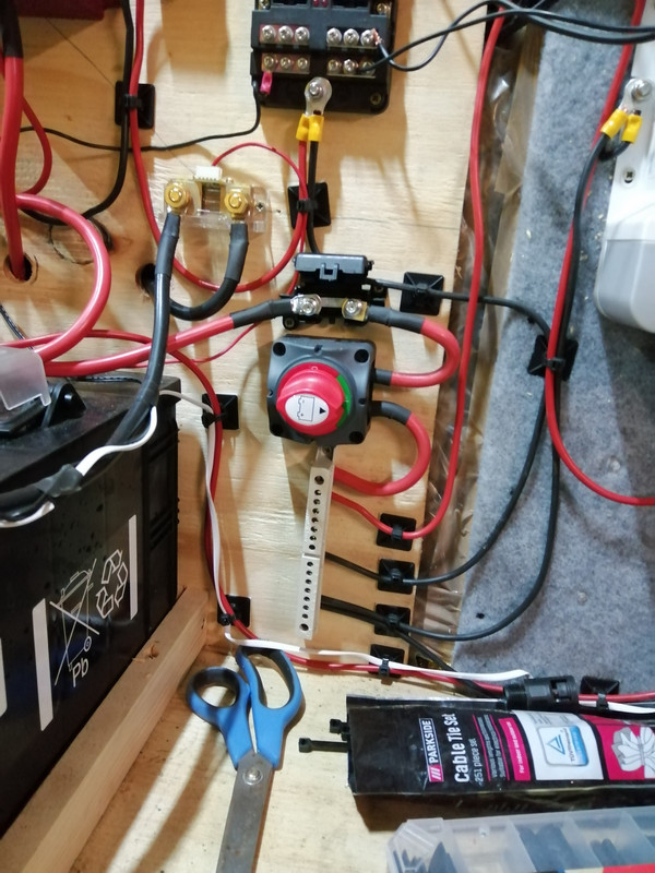
    More done.

    I have the isolator fitted & new bus bars, one for + and one for -

    Power comes from the Starter battery to the in on the b2b, via an 80A fuse. Out from the b2b routes through an 80A fuse to the battery.

    I have no suitable heavy bus bar for this, so it's easy to have all together on the terminal clamp. Stud clamps have been ordered.

    Power goes to the isolator from the battery and then via 40A fuse and then to the bus bar.

    Output 1 from the ProNautic goes to the + on the battery. Output 2 from the ProNautic goes via split charge relay to charge the starter battery.

    I have noticed that when I plug in shore power, the split charge relay is energised and I was getting 15v at the starter battery. However when I plugged shore power out, the relay stayed energised even after a while. I undid the link from the b2b and it disconnected before I left (It didn't reconnect when I put it back on). I'm surprised by this. I would've thought that the voltage from the ProNautic would've disappeared and therefore disconnected the relay.

    I wonder is there a need for the SCR at all, given that the outputs from the proNautic are isolated. I may be able to go directly to it.

    One remaining job is to add a feed to the b2b to indicate the engine running. There's a wire in the dash behind the glove box that I can take and run it to the battery box, and use the cables there to run back to the b2b

    IMG-20210116-171924.jpg

    IMG-20210116-171912.jpg

    IMG-20210116-171929.jpg

    IMG-20210116-171935.jpg


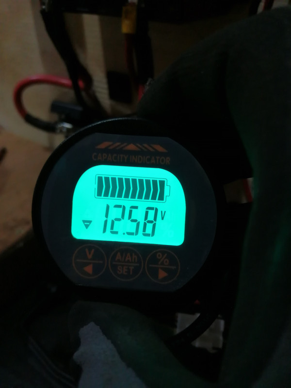
    Didn't realise the lighting was so poor, but here' the battery monitor

    IMG-20210116-161607.jpg


  • Posts: 5,238 ✭✭✭ [Deleted User]


    There's no point to the SCR. Get Rid, it's creating a feedback loop and defeating the B2B from operating. (€30 box making a £500 box redundant :pac:...I've a mate's boat I'm doing jobs on, factory fit, 3 alternators, 210A £600 Sterling Alt2B Charger anna £500 meter...they installed the Sterling box to disable the 160A $500 alternator, ignored that the meter was reading charge at 60A not the 250A I rewired it to and the D+ was hardwired to the B+ to turn off the battery light & prevent attention being drawn to the €1.5k of not working hardware onboard (meter was shyte too, I got rid))

    The SCR probably has a delay timer on disconnect to reduce contact wear from hysteresis switching. Because it's voltage sensing and as soon as you connect two batteries to a charger the voltage drops momentarily.

    Be aware that that battery isolator is only rated for off-load operation and will fail after a few years. If you use it too often to connect an inverter the inverter capacitor inrush will blow the bejaysus off the contacts and they'll be pitted and krusty after about 20 operations.

    I still think you've too many terminal strips. I'd use the fuse block for the small ones and a bus bars you don't have for the big ones.

    The trigger for the B2B you are looking for might be the coil of the Ford Split Charge contactor (reservations aside) or else there's usually one for the seat-belt alarm or handbrake sensor switch near the driver seat.

    When you get solar the SCR will have to be isolated from engine split charge (DPST normal closed relay).
    That SCR is fairly light duty..the insides are a bit weedy. Grand for solar, I can melt them if I try with not much effort.


  • Advertisement
  • Posts: 5,238 ✭✭✭ [Deleted User]


    PS yer eyelets are too big for that fuseblock. M5.


  • Registered Users, Registered Users 2 Posts: 6,260 ✭✭✭Buford T Justice


    There's no point to the SCR. Get Rid.

    Fair point
    Be aware that that battery isolator is only rated for off-load operation and will fail after a few years. If you use it too often to connect an inverter the inverter capacitor inrush will blow the bejaysus off the contacts and they'll be pitted and krusty after about 20 operations.

    Noted.
    The trigger for the B2B you are looking for might be the coil of the Ford Split Charge contactor (reservations aside) or else there's usually one for the seat-belt alarm or handbrake sensor switch near the driver seat.

    The one behind the glove box is an indicator specifically for the engine running. I suppose the ignition on / engine running is 6 of one. half a dozen of the other.
    When you get solar the SCR will have to be isolated from engine split charge (DPST normal closed relay).
    That SCR is fairly light duty..the insides are a bit weedy. Grand for solar, I can melt them if I try with not much effort.

    Will worry about that when the time comes.


  • Posts: 5,238 ✭✭✭ [Deleted User]


    The one behind the glove box is an indicator specifically for the engine running. I suppose the ignition on / engine running is 6 of one. half a dozen of the other.


    Engine running is better because it prevents the engine battery getting pancaked if you leave the key in the on position with the engine off.

    As an installer I have to failsafe it against the user. As a DIYer I know better than to leave switches in silly positions or at least have nobody to complain to except myself when I don't.


    In any case the B2B has a 60 sec initialising delay to reduce system wear as the alternator works very hard after a crank and the engine is cold.

    Will worry about that when the time comes.


    Figured you would.


  • Registered Users, Registered Users 2 Posts: 6,260 ✭✭✭Buford T Justice


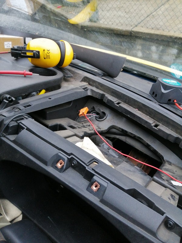
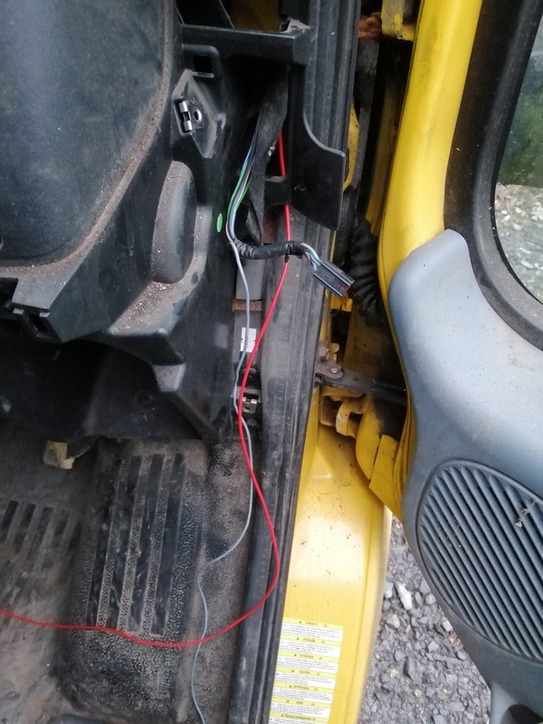
    So that wire under the dash didn't work, gave no reading out of it if the van was running or now. Moving on, I decided to use the cigarette lighter in the drivers dash. Someone had already butchered it to have a constant live rather than the ignition switched one (taken from the mirror controller no less, so I had to un-munge that while I was at it too.


    The manual says it won't start until it's over 13.3v and won't run down past it either, so I'd imagine with the ignition on only, it's a safe enough. Plus as you say, I know about it so it'd be my own fault.

    IMG-20210117-150347.jpg

    IMG-20210117-150351.jpg


  • Registered Users, Registered Users 2 Posts: 6,260 ✭✭✭Buford T Justice


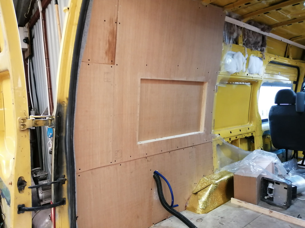
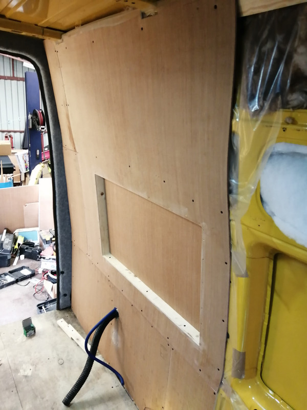
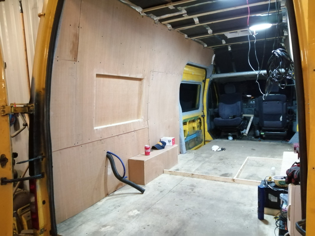
    Built a box in the back of the van to give a little extra legroom in the bed. I've gained 2 inches this way, and will get another two on the other side of the van when I do that too.

    Continued the vapour barrier behind the panel and it's all joined up again. Lots of taping up. Have a sheet cut to cover the remaining, but ran out of time to fit it today.

    I left a cut out to allow the conduit run up the van behind the barrier. It'll be covered with lining carpet, so should be good.

    IMG-20210131-170915.jpg


  • Registered Users, Registered Users 2 Posts: 6,260 ✭✭✭Buford T Justice


    Progress...


    IMG-20210217-201846.jpg

    IMG-20210217-201856.jpg


    I'm considering not bothering with the water heater for the van, or at least forgoing it to a later date. I recall rarely using it in the last van, there's quite a bit of scale on it it would seem, and there's no insulation on it. I can't justify shelling out on a new one, and I'm not overly enamoured to cut a hole in the side of the van for an antiquated water heater. I can retrofit on later I'd imagine.

    Jury's out


  • Posts: 5,238 ✭✭✭ [Deleted User]


    I'm considering not bothering with the water heater for the van,


    What is it? I'm curious.


    I recall rarely using it in the last van,


    Meanwhile, I'm designing a hydronic DHW system with conventional domestic radiators and a calorifier that also takes a feed from the engine coolant off a separate coil, mains via an electric element and 24V solar excess via an electric element...(dual voltage element)
    ...With the air heater as a backup because it's already mostly there. :pac:

    ...and a 2 gallon, recirculating shower with heat exchangers, filtering and thermostatically boosted recovery...something, something..I'm still beard scratching how it'll actually work.


    there's quite a bit of scale on it it would seem


    Circulate an anti-scale through it. eg vinegar on a closed-loop, 12v pump.


    and there's no insulation on it.
    Armaflex.

    I can't justify shelling out on a new one,


    I don't buy new anything for a camper except maybe batteries and solar because new domestic solar is cheaper than 12v.


    When you think about the usage of a camper most of the hardware has less than 200 hours on it.
    So pretty mind blowin how poor the standard is when stuff can't last that long. I buy used genuine products...same cost and you'll never see the end of them.


    and I'm not overly enamoured to cut a hole in the side of the van for an antiquated water heater.


    Yet people think huge intakes, vents and an exhaust for a gas fridge that still won't work after you do butcher your van is perfectly acceptable. :rolleyes:


    Jury's out


    If it's 24v or gas I might be interested.


    I've been watching this guys channel lately. He's a bright chap. Impressive skillset. You'll like him.


    Seem's to be a blue box fanboy...I try to not hold it against him.
    Also, he went down the expensive "more efficient" li-ion road now he's heating them in the Winter...:rolleyes:....
    I have yet to see li-ion be better than lead at anything other than energy density.
    When cost and practical applications are factored. Li-ion is not only underperforming but also a liability.


    The feckin' battery tells the chargers to turn off when it's cold!! Efficient me [rude word]. I can charge lead faster too because it's cold charge compatible and doesn't melt alternators.


  • Registered Users, Registered Users 2 Posts: 6,260 ✭✭✭Buford T Justice


    What is it? I'm curious.

    It's a Carver Cascade II

    You can see it on the side of the old van

    IMG-20200905-110914.jpg
    Armaflex.

    Thanks for that
    Yet people think huge intakes, vents and an exhaust for a gas fridge that still won't work after you do butcher your van is perfectly acceptable. :rolleyes:

    You've sold me on that front.

    If it's 24v or gas I might be interested.

    Gas - I have to actually assemble it to see if it still actually works.


  • Posts: 5,238 ✭✭✭ [Deleted User]


    Hrmmm...maybe useful to me (or something like that)...for that shower...dunno...I'd rather not have gas....I think I'll be a long time working on this shower.

    I'll have to build one in the mancave first. Loadsa lads are doing it and saying it's working ta-da...I wanna see how the pumps and filters hold up to a coupla months of soap and hair before I commit.


  • Advertisement
  • Registered Users, Registered Users 2 Posts: 6,260 ✭✭✭Buford T Justice


    I've been watching this guys channel lately. He's a bright chap. Impressive skillset. You'll like him.

    This guy takes perfection to a whole new level. He clearly has an abundance of time and money with the way he's building that yoke.

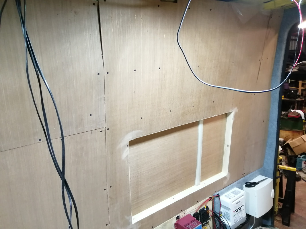
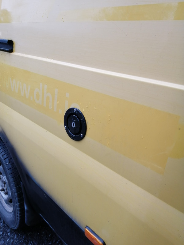
    In other news, I started on the passenger side of the van, with the same sort of idea as the drivers side. Since this was the side where the water tank is going I've installed the water inlet on the side. I've test fitted the tank, and there's space for the water heater between the tank and the wheel arch should I choose to install it.

    IMG-20210219-135435.jpg

    IMG-20210219-135427.jpg

    IMG-20210219-161006.jpg

    IMG-20210219-161017.jpg


  • Registered Users, Registered Users 2 Posts: 6,260 ✭✭✭Buford T Justice


    Picked up this stuff the other day. To be perfectly honest I got pissed off with the condensation on the inside of the van, and though it's not as bad with the weather currently decided to do something about it.

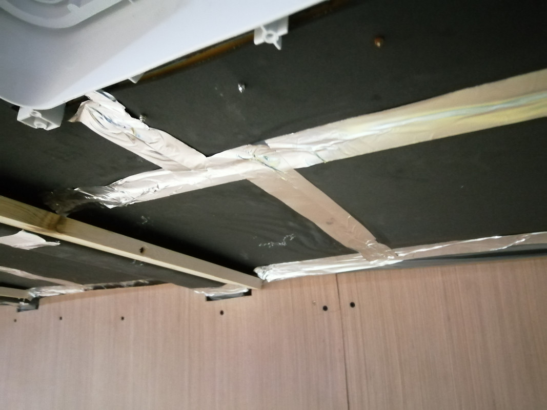
    This stuff has a vapour barrier built in, but I rekon I might have to still use a polythene sheet. I have to get some aluminium tape to cover the gaps.

    Also, I was trying to figure out what to do as regards batons for the roof / mounting the roof. I didn't want to use the 2x1 on it's end as it would end up losing another inch of the height of the roof. Putting the batons on their side and fixing directly to the roof supports would end up losing the same amount of height, so in the end I used 70mm screws and fixed them to the side of the roof supports at the same height as the bottom of the support = no height loss. Profit!

    IMG-20210219-185828.jpg


  • Posts: 5,238 ✭✭✭ [Deleted User]


    This guy takes perfection to a whole new level. He clearly has an abundance of time and money with the way he's building that yoke.


    I would say it's heavily biased on time and not his first rodeo. Seems like a genuinely good skin (there's hardly any youtoob channels I can watch on the matter that don't have me facepalming inside the first 5mins)

    Beta-nerd...I still outrank him...:p


  • Registered Users, Registered Users 2 Posts: 6,260 ✭✭✭Buford T Justice


    I agree, seems like a nice guy and he's building the van the way he wants, but doesn't seem to have any issues with money building it.

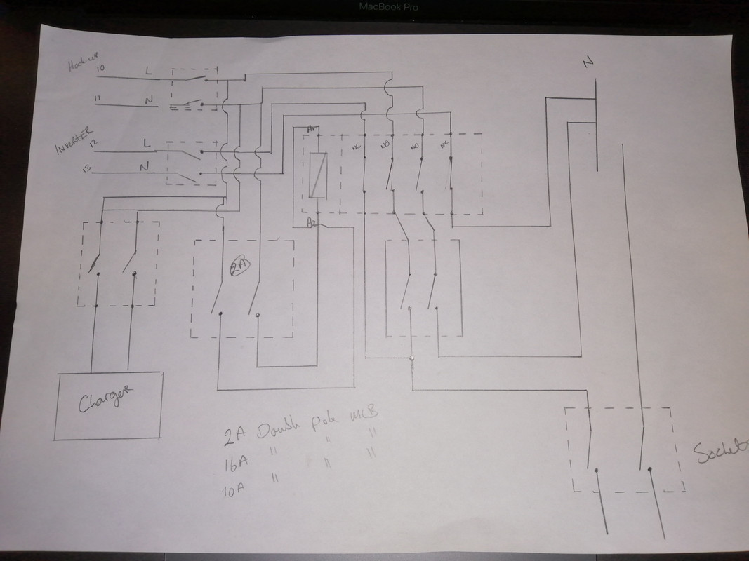
    In other news, I'm in the market for a new inverter. I've been trying some swanky 240v install where the default 240 supply in the van, and once it senses the shore connection it switches over to that for the supply for the van. I didn't do it right and am now learning an expensive lesson.

    I didn't use a double pole isolators for the coil isolator, or for the feed mcb to the sockets. It was working until I was switching between the two. I think there was a loop via the neutral with caused it. Tripped MCB's Blew the inverter fuse and tripped the mcb in the shed providing the shore power.

    I only tried the inverter again this evening and realised it.

    Needless to say I fucked it up good and proper, and my inverter has paid the price for it. Thankfully the ProNautic is fine, since it's fed directly from the shore power and not part of this concoction.


    This is what I was trying to achieve.

    IMG-20210220-203149.jpg

    Feel like a prize prick now


  • Registered Users, Registered Users 2 Posts: 6,260 ✭✭✭Buford T Justice


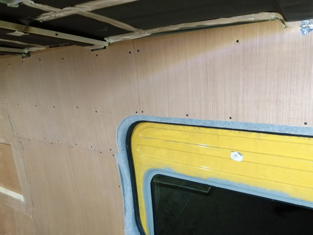
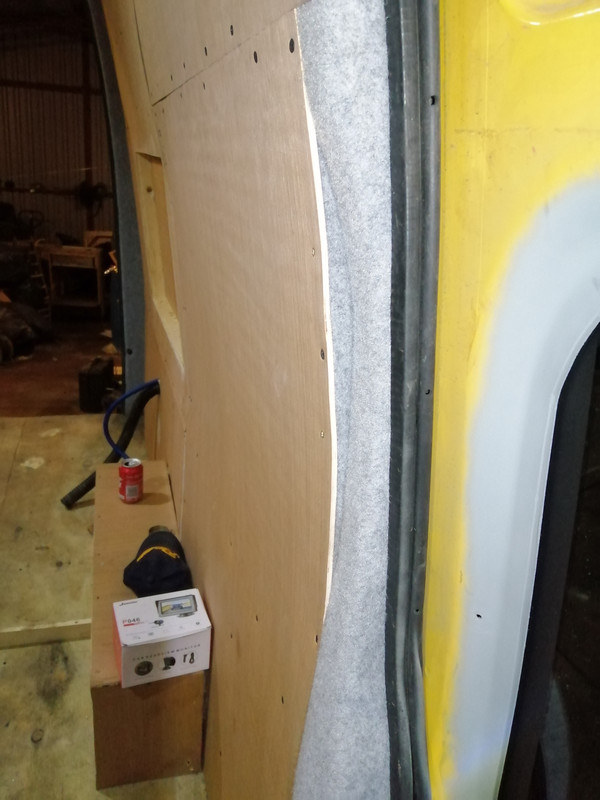
    Got my hands on some foil tape today - should've got some sooner. Finished out the lining of the van. I like how I finished around the sliding door, with the curve on the timber.

    I've applied the 2mm self adhesive neoprene before the lining carpet to give that a thermal break and then the lining carpet. My idea this time is that I'll line the panels when I'm finished the install since there'll be cupboards and all sorts going in. No sense in lining them if they won't be seen really.
    In this way I can line the panels on their own and tuck the edges up and under, and the edges around the door seals etc are already done. Tidy

    Since I've lined the roof with that stuff I mentioned earlier I have noticed two things:
    • Firstly, as this stuff obviously wasn't intended for this sort of stuff the gold lining that is stuck to the roof isn't bonded as well to the actual foam and it's come away in a couple of spots. I've glued it back up and we'll wait and see. It's not a big deal unless huge swathes of it start to fall down. Man will I be pissed if I have to do this again. In hindsight, I should've stuck it the other side up. Today is a real day of lessons.
    • Secondly, the since the river of condensation is no more on the roof of the van, drips are more obvious as leaks. The skylight is still leaking, albeit slightly. There as an unmerciful and unrelenting shower today for about an hour and a half. I spotted one drip falling and when I pressed the lining there was two to three drips that fell. It's a leak but a minor one. I need to re seal the seams of the roof in the better weather so I'll re-seal the skylight while I'm at it.

    IMG-20210220-183405.jpg

    IMG-20210220-183411.jpg

    IMG-20210220-183433.jpg

    IMG-20210220-183437.jpg

    IMG-20210220-183448.jpg

    IMG-20210220-183502.jpg


  • Registered Users, Registered Users 2 Posts: 6,260 ✭✭✭Buford T Justice


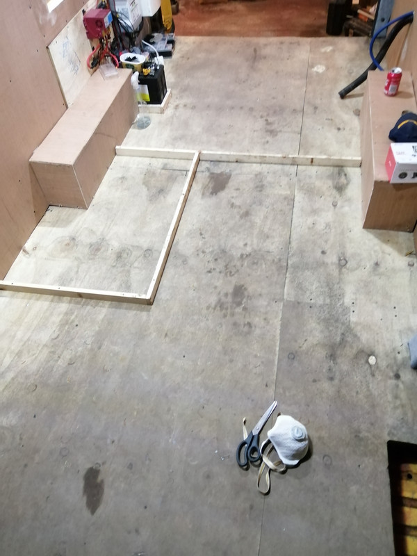
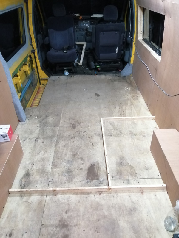
    So this is a shot of the van empty, with the layout lined for the toilet and the bed.

    My conundrum is space(duh). With the width of the toilet and the kitchen, having the seats on the drivers side it'll be way too narrow to get past the seats to the kitchen area. It may be a case of moving the seats forward.

    The kitchen unit that I have is unsuitable. It's too big and bulky for what I need. I'm thinking of getting am integrated cooker / sink as it has a smaller footprint than the one I have, but the tradeoff is the grill, which was useful. An alternative is to have the seats in front of the kitchen, but then there'd be a big empty chasm of unused space on the left side of the van.

    I'm open to suggestions from people as to what I could do here.

    IMG-20210220-183529.jpg

    IMG-20210220-183540.jpg

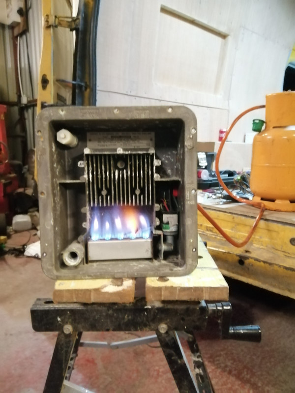
    On a positive note, the gas boiler is working. Just to give it a rinse and check for leaks.

    IMG-20210220-190539.jpg


  • Advertisement
  • Posts: 5,238 ✭✭✭ [Deleted User]


    I agree, seems like a nice guy and he's building the van the way he wants, but doesn't seem to have any issues with money building it.


    Arah sher you and I both know if you are happy to play the waiting game and wheel and deal then you don't pay the asking price.


    Besides blue boxes are cheap shyte. You're buying an app and marketing not a reliable high quality piece of hardware.
    I had a look at the battery episode and saw his tinternet machine. He's running firefox and chrome on PC. If that doesn't tell ya all ya need to know about a guy...

    In other news, I'm in the market for a new inverter.


    Huzzah! I never liked yer old one.

    I've been trying some swanky 240v install where the default 240 supply in the van, and once it senses the shore connection it switches over to that for the supply for the van.


    That's basic. Swanky is an interlock changeover with a delay.
    Neater than dedicated sockets no arguments.


    I didn't do it right and am now learning an expensive lesson.


    Cheaper than goin' to "sparky college" though?


    I didn't use a double pole isolators for the coil isolator, or for the feed mcb to the sockets. It was working until I was switching between the two. I think there was a loop via the neutral with caused it.


    You can get away with coupling one leg. ie. you can tie all the neutrals and not have issue. I don't because I don't like it but fellars smarter than I am say it's kosher.


    If you put utility mains on the output of an inverter it'll dodo it right fast. If you have continuity between L and N on the unpowered inverter output that's the failure mode (shorted output). Defeckt: dead FETs.

    Needless to say I fucked it up good and proper, and my inverter has paid the price for it. Thankfully the ProNautic is fine, since it's fed directly from the shore power and not part of this concoction.


    Yurp


    Just to make ya feel better about sending yer bargain basket inverter to silicon heaven here's two I've killed previously.


    544430.jpg

    That's a €2.5k 2.4kVA MasterApprenticeVolt that was just sh1t start to finish and it died (twice) in a failed attempt to met specification under duress.


    544431.jpg

    That's a €1.5k 2.2kVA Studer I destroyed with a wire making the fan spin faster..corrupted the main IC.


    This is what I was trying to achieve.


    Looks fine. As in I'm not sure you've found the issue. Maybe yer contactor isn't fast enough. It really ought to be supply #1 -> off -> supply #2.


    Feel like a prize prick now


    I'll give you honourable mention.
    You didn't make the podium though.


  • Posts: 5,238 ✭✭✭ [Deleted User]


    I'm open to suggestions from people as to what I could do here.

    image-13.png


  • Registered Users, Registered Users 2 Posts: 6,260 ✭✭✭Buford T Justice


    Looks fine. As in I'm not sure you've found the issue. Maybe yer contactor isn't fast enough. It really ought to be supply #1 -> off -> supply #2.

    I got the idea from this guy, and I have the same Schneider contactor


  • Posts: 5,238 ✭✭✭ [Deleted User]


    I got the idea from this guy, and I have the same Schneider contactor


    Sparks for 20 years :pac:....


    Few Notes:


    The Consumer unit is too big.

    If you have automatic switching between Shore and Inverter than you only need one RCD on the contactor output (if the charger is double insulated or use an RCBO for that).

    There's no need for an MCB on most inverters because they can't produce the surge power required to trip them.

    Shore inverter priority ought to have priority to shore mains because it's abundant and the inverter uses battery.

    There's no delay timer on the changeover?


    EkhgfxY.jpg


    I've pretty much the same system as the one you made Mr. T except I'm using a DPDT contactor instead of a DPST NO and a DPST NC so the two can never be made at the same time (but an arc can bridge the contacts while switching if yer super unlucky).


    He's saying that the inverter was CTE. I think that's just a floating earth. All inverters I've seen look CTE until you neutralise them. I've heard that neutralising kills cheapys but not something I've experienced. All mine are TN-S and no issue.
    I have a durshyte MSW...I think I might neutralise that for science and see if there's any truth to the claim or if there's other factors at play.


    I suggest you line check your setup and ensure that mains can never backfeed the inverter output in any configuration.


  • Posts: 5,238 ✭✭✭ [Deleted User]


    I decided to put my money where my mouth is. Earth leakage protection aka life harm protection is the most important and overlooked part of electrical design in off-grid.
    It falls into the; if it's too complicated to understand then it's probably not relevant department..and besides the system works without it.


    Sparky A: blew up inverter
    Sparky B: said it sounds sketchy... wouldn't recommend.
    Joe Public A: blew up inverter
    Joe Public B: blew up inverter
    Mariner fitter: Never had an issue
    Myself: never had an issue, haven't tried every topology.


    Accepting that adapting a critical mindset..you don't know until you know, with consideration to those who seem to know what they're doing haven't had issue and those with no relevant experience/qualifications/problem-solving skills are having issues.
    This leads me to consider that people blowing up inverters are blaming the neutralising link when there's other factors at play. Much like people blame batteries for system failures and not chargers.

    Here's the cheapest nastiest inverter I have at my disposal.
    As she comes standard, looking like a centre tapped earth but it's just a floating reference.

    gnQoZgD.jpg

    Live -> Earth: 131V
    Neutral -> Earth: 106V

    Here we see my tester flagging "No Earth"

    BpZQIFM.jpg

    That means no earth reference and/or continuity.
    RCDs (GFIs) are not enabled in this configuration.

    So let's TN-S; tied neutral supply.
    ..and see if she retains her smoke...

    TsA18Ri.jpg


    Live -> Earth: 238V
    Neutral -> Earth: 0V

    If that Wago was an RCD it could now save yer life.

    I don't know how people are blowing inverters I expect it's by putting unsynchronised mains on the output or perhaps the DC input.

    Remember. The earth and the neutral are the same conductor.
    One is allowed to conduct.
    Thuther isn't.
    We are all birds on the wire with regards to the potential difference.

    fotolia_2087139_XS.jpg

    [Edit:] To be sure, to be sure, to be sure I just linked the PE (AC earth) to the Ground (DC negative) with the Earth tied to the neutral and smoke retained...inverter still working.


  • Advertisement
Advertisement