Advertisement
If you have a new account but are having problems posting or verifying your account, please email us on hello@boards.ie for help. Thanks :)
Hello all! Please ensure that you are posting a new thread or question in the appropriate forum. The Feedback forum is overwhelmed with questions that are having to be moved elsewhere. If you need help to verify your account contact hello@boards.ie

Phase 6 science exam papers

245

Comments

  • Moderators, Home & Garden Moderators, Technology & Internet Moderators, Regional East Moderators Posts: 12,662 Mod ✭✭✭✭2011


    a single phase fluorescent lighting load takes a supply current of 16 amps from 230volt 50hz supply at a power factor of .85 lagging.

    Here are a few clues:

    Power = V x I x PF = 230 x 16 x 0.85 = 3128 watts

    Power = I^2 x R

    R = P / (I^2)
    R = 3128 / (16^2) = 12.23 ohms = resistance of fluorescent lighting load t

    Cos^-1 (0.85) = 31.79° as the circuit is inductive the current is lagging.

    Calculate reactive power.
    From this work out XL.

    Next calculate Xc

    Xc = 1/ωC
        = 1 / (2x pi x fC)


    Where:
    f = 50 Hz
    C = 60 x 10^-6

    Subtract Xc from XL.

    Use Pythagoras theorem to solve.

    Remember that as the capacitor is connected in parallel with the lighting load 230V will be applied across it.


  • Registered Users, Registered Users 2 Posts: 1,878 ✭✭✭arse..biscuits


    2011 wrote: »
    Here are a few clues:

    Power = V x I x PF = 230 x 16 x 0.85 = 3128 watts

    Power = I^2 x R

    R = P / (I^2)
    R = 3128 / (16^2) = 12.23 ohms = resistance of fluorescent lighting load t

    Cos^-1 (0.85) = 31.79° as the circuit is inductive the current is lagging.

    Calculate reactive power.
    From this work out XL.

    Next calculate Xc

    Xc = 1/ωC
        = 1 / (2x pi x fC)


    Where:
    f = 50 Hz
    C = 60 x 10^-6

    Subtract Xc from XL.

    Use Pythagoras theorem to solve.

    Remember that as the capacitor is connected in parallel with the lighting load 230V will be applied across it.

    It's not that complicated.


  • Registered Users, Registered Users 2 Posts: 1,878 ✭✭✭arse..biscuits


    a single phase fluorescent lighting load takes a supply current of 16 amps from 230volt 50hz supply at a power factor of .85 lagging.
    a 60uf capacitor is used to improve the power factor of the circuit,determine the new value of supply current.
    can anyone show me how to do this one and write the steps in order to achieve this.
    cheers folks.

    Find the angle which the current is lagging by.
    Calculate Xc
    Calculate the current through the capacitor (V/Xc)
    Capacitor current leads by 90 degrees
    You now have two currents and you have to add them using phasor addition


  • Registered Users, Registered Users 2 Posts: 163 ✭✭BrianDug


    Ok so what you know is:
    Incoming supply ampere is 16A
    P.F = 0.85
    V = 230

    So if we focus on this for a minute we can draw a power triangle soley based on this information.
    On the top line of our power triangle:

    kW = 230 x 16 x 0.85 = 3128W (3.128 kW)
    kVA = 230 x 16 = 3680VA (3.680 kVA)
    kVAr = by Pythagoras theorem sqrt(kVA^2 - kW^2)
    = sqrt(3680^2 - 3128^2) = 1938.56 VAr (1.938 kVAr)
    Power Factor = kW/kVA so 3128/3680 = 0.85 (as expected)

    We could also draw the power triangle using just the current so in the kVA position we would have 16A, in the kW position we would have 13.6 A (16A x 0.85), and in the kVAr position we would have sqrt(16^2 - 13.6^2) = 8.4285A. Doing it this way is just another way of looking at the power triangle. Then power is of course V x I & so kW = 230 x 13.6A = 3128W, kVA = 230 x 16A = 3680VA etc etc...

    Ok so now for adding the capacitor, we know in simple terms that inductive reactance/ballasts/coils etc will cause the current to lag the voltage and the worse the power factor the higher the "wasted current"/kVAr/power so in order to help reduce our reactive power/kVAr we need to add a capacitor that will "suck up" the bad power and help reduce our power factor and wasted power.

    We are told our capacitor is 60uf so what we are essentially looking to do is find how much current this capacitor requires. By ohms law I = V/R.
    Xc can be thought of as R in your case so it will be I = V/Xc.

    To find XL its 1/2*pi*frequency*C = 1/2*pi*50*60x10^-6 = 53.05ohms
    So I = V/Xc = 230/53.05ohms = 4.3347A

    So the capacitor will "take" 4.3347A from the supply. A way to think of it is XL & XC are always fighting each other and that generally XL will always be bigger than XC.

    Looking back at the current results we now know with the inductor/XL is 8.4285A and XC is 4.3347A. These two values are all we need to solve. To find our new Total Current/kVA the formula is

    Z = sqrt(r^2 + (XL^2 - XC^2) which is same as
    Z = sqt(Ir^2 + (IXL^2 - IXC^2)
    Z = sqrt(13.6A^2 + (8.4285A - 4.3347A)^2 = 14.20A

    14.20A is the total current been drawn from the system so 230V x 14.20A = 3266VA

    PF = R/Z = 3128W/3266VA =0.95 or 13.6A/14.20A = 0.95 etc...
    Our system was drawing 3680VA(or 16A) before we added a capacitor. With a capacitor its 3266VA( or 14.20A) so we are using less power now.

    Try visualise whats going on and it all becomes clear. I tried to do out as many steps as possible so you can see whats happening. I hope I havent confused you!


  • Registered Users, Registered Users 2 Posts: 1,878 ✭✭✭arse..biscuits


    Current 1 is 16 A, lagging by an angle of (cos^-1 0.85) 31.8 degrees

    Xc=1/(2 * pi * f * C) = 53.05 ohms
    Current 2 = V/Xc = 230/53.05=4.34 A, leading at an angle of 90 degrees

    I1 = 16A @-31.8 degrees
    I2 = 4.34A @90 degrees

    phasor addition
    x = (I1 * cos thita 1) + (I2 * cos thita 2) = (16 * cos -31.8)+(4.34 * cos 90)=13.6
    y = (I1 * sin thita 1) + (I2 * sin thita 2) = (16 * sin -31.8)+(4.34 * sin 90)= -4.09

    Now do pyth. theorm with these values (you can drop the minus)

    Total current = Square root (13.6^2 + 4.09^2) =14.2 A


  • Advertisement
  • Registered Users, Registered Users 2 Posts: 163 ✭✭BrianDug


    Ay but do they show you how to do it this way?

    Many ways to do it, best way is a method that you can follow step by step and understand. Not good to be doing calculations if you dont know whats happening.

    I'm sure you will have plenty of samples done in your notes.


  • Registered Users, Registered Users 2 Posts: 1,878 ✭✭✭arse..biscuits


    It is difficult to explain these types of questions here, face to face is a lot easier. I have been teaching this type of stuff for years and my students are always happy.


  • Moderators, Home & Garden Moderators, Technology & Internet Moderators, Regional East Moderators Posts: 12,662 Mod ✭✭✭✭2011


    BrianDug wrote: »
    Many ways to do it, best way is a method that you can follow step by step and understand.

    Exactly.
    There are many correct ways of solving this, what appears complicated for one person may appear straight forward to another.


  • Registered Users, Registered Users 2 Posts: 51 ✭✭kingden2006


    thanks lads for the help really appreciated and understood,im starting phase 6 now in january got all credits in phase 4 so its not really the maths the worries me its more the plcs,and the questions on them,they appear to be difficult along with some electronic questions.
    has anyone any idea on those,are they difficult??they look difficult.
    and everyone i have been talking to tells me yhat phase 6 is easier than phase 4?i can"t imagine that to be true can anyone shed any light on this?
    thanks again lads and happy x-mas to you all


  • Registered Users, Registered Users 2 Posts: 51 ✭✭kingden2006


    sorry for the spelling mistakes lads was in a rush.


  • Advertisement
  • Registered Users, Registered Users 2 Posts: 316 ✭✭johnnyfruitcake


    If you got credits in phase 4 you'll breeze phase 6, plc questions are mostly about drawing out ladder diagrams, not very hard at all.


  • Registered Users, Registered Users 2 Posts: 148 ✭✭sparcocars


    Its not that its easier than phase 4 but its not as big of a jump as it is in phase 4 from phase 2. You still need to put the work in but if you did well in phase 4 then you should be okay. A lot of the stuff looks hard when you look at it now but when its explained to you in class it will begin to make sense. When i started phase 6 i thought i was never going to get the plc's but they actually turn out to be relatively straight forward after a week or two. Its nearly lime learning a new language. I got all credits in phase 4 and then got all credits in phase 6. Just keep the head down and you should be fine.


  • Registered Users, Registered Users 2 Posts: 51 ✭✭kingden2006


    cheers lads.can anyone answer this question and show me which way its done from start to finish cheers lads.
    A 450 dc shunt motor has an armature resistance of 0.185ohms.if the field current is 20 amps and the load current is 160 amps,calculate the efficiency of the motor?(neglect iron and mechanical losses)

    and here"s another quick two while im here.
    A three phase motor is connected in delta and takes 90 amps from the supply.calculate the current in each winding?

    the copper losses of a transformer are 90kw on half load.calculate the copper losses at three quarter full load


  • Registered Users, Registered Users 2 Posts: 1,878 ✭✭✭arse..biscuits


    Armature current =160-20=140A

    Power losses
    (Field) P=V.I=450x20=9000W
    (armature) P=I^2.R=140x140x0.185=3626W
    Total = 12,626W

    Power input = V.I = 450x160=72000W

    Power output =input - losses = 72000 - 12625=59374W

    Eff = out/in = 59374/72000=0.8246

    82.46%


  • Registered Users, Registered Users 2 Posts: 1,878 ✭✭✭arse..biscuits


    A three phase motor is connected in delta and takes 90 amps from the supply.calculate the current in each winding?


    I(phase)=90/root 3=51.96A


  • Registered Users, Registered Users 2 Posts: 1,878 ✭✭✭arse..biscuits


    90kw on half load.calculate the copper losses at three quarter full load

    Full load copper losses = 90/0.5^2=360kW

    Copper losses at 3/4 of full load = 360x0.75^2=202.5kW


  • Registered Users, Registered Users 2 Posts: 51 ✭✭kingden2006


    cheers arse..biscuits..gentleman


  • Registered Users, Registered Users 2 Posts: 51 ✭✭kingden2006


    hers another one for you lads if anybody can answer it.
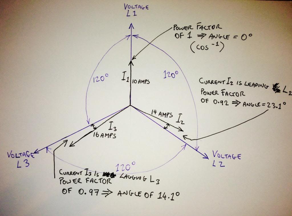
    three single phase loads are connected to a 400volts 50hz supply.calculate the magnitude of current flowing in the neutral.
    L1 IS 10 AMPS AT UNITY POWER FACTOR.
    L2 IS 14 AMPS AT .92 LEADING
    L3 IS 16 AMPS AT .97 LAGGING.?
    COULD YOU PLEASE SHOW ME THE STEPS ALSO.
    THANKS LADS AND HAPPY NEW YEAR TO YOU ALL


  • Registered Users, Registered Users 2 Posts: 51 ✭✭kingden2006


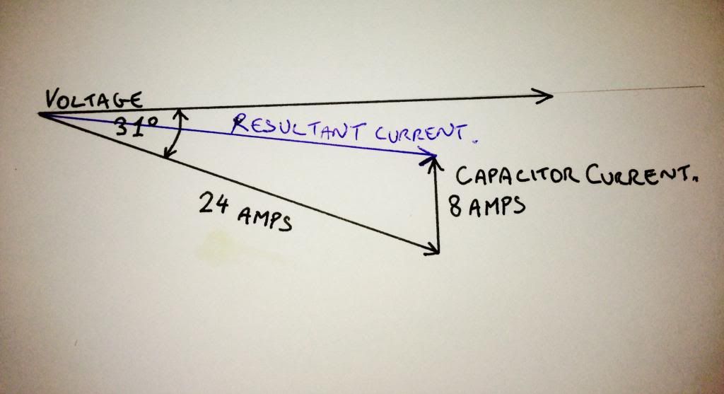
    A SINGLE PHASE FLUORESCENT LIGHTING LOAD TAKES A SUPPLY CURRENT OF 24 AMPS FROM A 230 VOLT 50HZ SUPPLY AT A POWER FACTOR OF 0.85 LAGGING.
    A POWER FACTOR CORRECTION CAPACITOR TAKING 8 AMPS IS USED TO IMPROVE THE POWER FACTOR OF THE CIRCUIT,DETERMINE THE NEW VALUE OF THE SUPPLY CURRENT AFTER POWER FACTOR CORRECTION?


  • Moderators, Home & Garden Moderators, Technology & Internet Moderators, Regional East Moderators Posts: 12,662 Mod ✭✭✭✭2011


    hers another one for you lads if anybody can answer it.
    three single phase loads are connected to a 400volts 50hz supply.calculate the magnitude of current flowing in the neutral.
    L1 IS 10 AMPS AT UNITY POWER FACTOR.
    L2 IS 14 AMPS AT .92 LEADING
    L3 IS 16 AMPS AT .97 LAGGING.?
    COULD YOU PLEASE SHOW ME THE STEPS ALSO.
    THANKS LADS AND HAPPY NEW YEAR TO YOU ALL

    The neutral current is equal to the phasor sum of the 3 currents.

    When this is drawn out as shown in the diagram below the solution should become clear.

    Does this make sense?
    Can you take it form here?

    Neutralcurrent.jpg


  • Advertisement
  • Moderators, Home & Garden Moderators, Technology & Internet Moderators, Regional East Moderators Posts: 12,662 Mod ✭✭✭✭2011


    A SINGLE PHASE FLUORESCENT LIGHTING LOAD TAKES A SUPPLY CURRENT OF 24 AMPS FROM A 230 VOLT 50HZ SUPPLY AT A POWER FACTOR OF 0.85 LAGGING.
    A POWER FACTOR CORRECTION CAPACITOR TAKING 8 AMPS IS USED TO IMPROVE THE POWER FACTOR OF THE CIRCUIT,DETERMINE THE NEW VALUE OF THE SUPPLY CURRENT AFTER POWER FACTOR CORRECTION?

    Have a look at this diagram and see if you can now solve this:

    Neutralcurrent2.jpg


  • Registered Users, Registered Users 2 Posts: 51 ✭✭kingden2006


    sorry 2011 still lost,going to have to get the books out again,cheers for taking the time,i do understand parts of it.
    im starting phase 6 now on monday just wanna get a bit of a head start or understanding.
    happy new year 2011.


  • Closed Accounts Posts: 14,158 ✭✭✭✭hufpc8w3adnk65


    sorry 2011 still lost,going to have to get the books out again,cheers for taking the time,i do understand parts of it.
    im starting phase 6 now on monday just wanna get a bit of a head start or understanding.
    happy new year 2011.
    Just reading some if the questions here make me so glad I'm finished my time! My advice is study study study while your in phase six! Like every night after fas go home and re read everything and if you don't understand something ASK a question and keep asking till you understand!


  • Registered Users, Registered Users 2 Posts: 1,878 ✭✭✭arse..biscuits


    sorry 2011 still lost,going to have to get the books out again,cheers for taking the time,i do understand parts of it.
    im starting phase 6 now on monday just wanna get a bit of a head start or understanding.
    happy new year 2011.

    Where are you doing phase 6?


  • Registered Users, Registered Users 2 Posts: 51 ✭✭kingden2006


    doing phase 6 in sligo IT arse biscuits..


  • Closed Accounts Posts: 13,422 ✭✭✭✭Bruthal


    sorry 2011 still lost,going to have to get the books out again,cheers for taking the time,i do understand parts of it.
    im starting phase 6 now on monday just wanna get a bit of a head start or understanding.
    happy new year 2011.

    You can use the diagram drawn out like 2011 has done, and use pythagoras stuff to calculate the unknown sides of triangles, to get the currents.


  • Moderators, Home & Garden Moderators, Technology & Internet Moderators, Regional East Moderators Posts: 12,662 Mod ✭✭✭✭2011


    sorry 2011 still lost,going to have to get the books out again,cheers for taking the time,i do understand parts of it.

    I think it is preferable to assist people with exam type questions rather than just answer the question directly so that they learn how to deal with these problems themselves.

    If you can be more specific about the parts of that you do not understand feel free to ask. We have plenty of helpful posters with a wealth of experience such as Bruthal.
    im starting phase 6 now on monday just wanna get a bit of a head start or understanding.

    If you have not covered this material yet you should not be concerned.


  • Registered Users, Registered Users 2 Posts: 51 ✭✭kingden2006


    i understand everything that you"ve done there 2011 but it"s just getting from there to the next stage i can"t work out.
    no i"ve never done any of this before 2011,phase 4 totally different questions.


  • Moderators, Home & Garden Moderators, Technology & Internet Moderators, Regional East Moderators Posts: 12,662 Mod ✭✭✭✭2011


    With reference to the first question you asked:
    So you understand, how I worked out the angle, the difference between leading & lagging currents, that the 3 phase voltages are electrically 120° apart?


  • Advertisement
  • Registered Users, Registered Users 2 Posts: 51 ✭✭kingden2006


    yes that"s all easy 2011,they either lead or lag and the closer it is to unity or 1 the better and cheaper it normally lags 120 degrees out of phase and i know how to do the phasor diagram and get the phase angle..


Advertisement