Advertisement
If you have a new account but are having problems posting or verifying your account, please email us on hello@boards.ie for help. Thanks :)
Hello all! Please ensure that you are posting a new thread or question in the appropriate forum. The Feedback forum is overwhelmed with questions that are having to be moved elsewhere. If you need help to verify your account contact hello@boards.ie
Help Keep Boards Alive. Support us by going ad free today. See here: https://subscriptions.boards.ie/.
If we do not hit our goal we will be forced to close the site.

Current status: https://keepboardsalive.com/

Annual subs are best for most impact. If you are still undecided on going Ad Free - you can also donate using the Paypal Donate option. All contribution helps. Thank you.
https://www.boards.ie/group/1878-subscribers-forum

Private Group for paid up members of Boards.ie. Join the club.

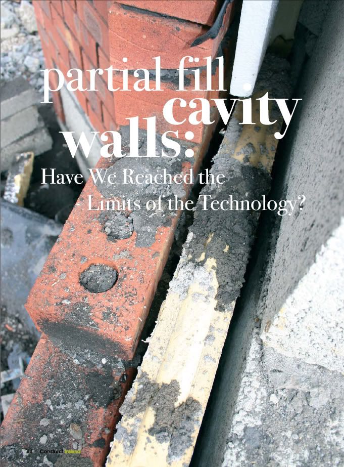
Is cavity wall construction obsolete, and if so what's the alternative?

2

Comments

  • Closed Accounts Posts: 8,156 ✭✭✭Iwannahurl


    Hi

    I worked as a brick/blocklayer in the UK for quite a while and we ALWAYS built the inner leaf first with 5" aerated blocks and after it had set we would strap the insulation onto the wall and tape the joins. Then build the outer leaf keeping the cavity clean. At the reveals these were filled with strips of PU insulation thus avoiding cold bridging. Easy! I have never seen this method employed over here. You see isulation bats flapping around in cavitys on a lot of sites. I blame the drive by engineers myself!


    All too common, in my personal experience. It's an inherent flaw of the system, IMO, as well as being due to ignorance and apathy among the various (un)interested parties. I've been astonished at the lack of basic knowledge of how insulation is supposed to work and of why attention to such details is so important.


    PFCWC.jpg


  • Registered Users, Registered Users 2 Posts: 1,632 ✭✭✭heinbloed


    Taped over the wall plugs? Never seen anything alike, thanks Sinnerboy.


  • Closed Accounts Posts: 5,433 ✭✭✭sinnerboy


    Well sort of over the ties Heinbleod. Where the tape approaches them you cut it down the middle. The tape passes the tie like two fingers holding a cigarette. All joints are taped, horizontal and vertical especially at corners. Before the bricks follow on it is easy to check boards are tight together and tight to the inner leaf.

    This is not normal practice..... you have to hit them over the head with rotten fish to do this.

    The other picture above shows the awful norm.


  • Closed Accounts Posts: 8,156 ✭✭✭Iwannahurl


    A thought occurs: apart from the fact that merely placing one brick/block on top of another eventually results in a construction that looks like a house, the work illustrated in post #32 above represents a complete waste of time, materials and money.

    How can that be regarded as "economical" in any meaningful sense of the word?


  • Registered Users, Registered Users 2 Posts: 1,504 ✭✭✭BarneyMc


    thanks for posting the image sinnerboy.

    Are there no wall ties used then?


  • Advertisement
  • Registered Users, Registered Users 2 Posts: 14,547 ✭✭✭✭Poor Uncle Tom


    Iwannahurl wrote: »
    ...the work illustrated in post #32 above represents a complete waste of time, materials and money.
    Agreed,
    The work illustrated in post #32 is representative of bad workmanship. This method can not be dismissed on one picture which represents the trade at it's worst. I know of a lot of Blocklayers/brickies who take serious pride in their work and would walk off a building site before putting their name to work like that.
    Iwannahurl wrote: »
    ...How can that be regarded as "economical" in any meaningful sense of the word?
    That example can not be regarded as being economical. However if that job had been done correctly, and fit for purpose, then it would represent an economical build.

    At the end of the day here we are just spouting about the possible merits of one building type over another, in doing so we should assume that the works are being carried out to an acceptable standard and not rely on one picture to throw everyone into panic. I'm sure there are horror pictures of ICF (I've seen the formwork burst out over pressure of concrete, etc.,), TF (I've asked for entire frames to be removed from sites on occasions..), and all other forms of construction. Choosing a picture of cavity wall construction at it's worst and asking about it's viability is scaremongering, imo.


  • Closed Accounts Posts: 5,433 ✭✭✭sinnerboy


    BarneyMc wrote: »
    thanks for posting the image sinnerboy.

    Are there no wall ties used then?

    They don't show up well in the photo but the black "X" pvc insulation restraint clips do. Zoom in the photo and there they are :)

    If partial fill is installed badly i.e ( and I have seen all of the following )

    - incompletely - areas simply left out
    - gaps of 5 , 10 , 15mm + at board edges
    - leaning forward from the inner leaf leaving a gap behind the insulation board
    - mortar dropping allowed to collect on the board joints

    ( in other words as per photo in post 32 ) then cold cavity air bypasses the insulation and reduces its performance dramatically.

    But if built in the manner described in photo I posted - all of these issues are avoided. Not to mention the small matter that the airspace is much easier to maintain clean from mortar droppings . You must still check on site to ensure this .

    It is worth investing €50 on an "American Cop" style torch with which you can adjust the light beam down to a very narrow and concentrated light beam. Using such a torch you can easily inspect the airspace up to 2 storys of cavity wall height.

    To answer the thread title I paraphrase Mark Twain.

    Reports of the death of the cavity wall are exaggerated.


  • Registered Users, Registered Users 2 Posts: 47,143 ✭✭✭✭muffler


    sinnerboy wrote: »
    Reports of the death of the cavity wall are exaggerated.
    You'll go down in history :)


  • Registered Users, Registered Users 2 Posts: 1,632 ✭✭✭heinbloed


    I see, thanks, Sinnerboy.

    So the boards would go up first (including the ties)and then both walls? I think the taping would have to be done on both sides of the boards?

    If the boards warp (what they will do if not glued down to a wall over their entire surface, creating a 'sandwich', a 'SIP')) the taping would result as a reinforcement, causing not only the individual boards to warp slightly but will cause a sort of a wave pattern over the wall structure. Combining the expansion and contraction forces over the entire wall since the boards forming one unit after taping them, the forces now working together at the weakest points.

    And the ties then cuting over the years of movement into tape and board?

    The warping is caused by differing temperatures the boards are exposed to, inside and outside (warm and cold) as well as changing moisture loads and wind pressure via seeping and ventilation holes.
    PUR and PIR boards are particular prone to this warping effect. EPS in principle as well, but not as bad. And has no gas to lose.

    Are there longterm researches done verifying this method, for example old walls opened in exposed areas and the taping, boarding controlled by independant researchers?


  • Closed Accounts Posts: 5,433 ✭✭✭sinnerboy


    The sequence is
    1. the inner-leaf is built including ties up to about 2m high
    2. the boards are installed and then the black X restraints are placed over the ties to hold the boards tight to the inner leaf .
    3. then tape the boards - ( outer face only )
    4. the outer-leaf is then built up

    Then repeat using a timber board across the top of the cavity to stop mortar falling into it. It is also good practice to leave every 8th of 9th brick or block out from the very first course of the outer leaf thus leaving a series of inspection points at the very base of the cavity. These small openings also allow access to clean the base of the cavity if there were still some accidental mortar droppings. Then they too are filled in .

    I have seen many cavity walls opened up in my time and have never seen boards warp never mind to the extent that they would tear tape. The pvc restraints work well according to my own eyes.


    images?q=tbn:ANd9GcTANBm2RcVj0ghAAaKlh19qQ7EcwUypjMpNzw1A_h46dkHLnn8ebw
    .


  • Advertisement
  • Registered Users, Registered Users 2 Posts: 5,422 ✭✭✭just do it


    sinnerboy wrote: »
    This is not normal practice..... you have to hit them over the head with rotten fish to do this.

    And was there an extra cost to get them to do this?


  • Closed Accounts Posts: 5,433 ✭✭✭sinnerboy


    not on my watch


  • Registered Users, Registered Users 2 Posts: 1,632 ✭✭✭heinbloed


    If the boards are not sealed at the 'damp' side i.e. taped at the internal facing side then inevitably moisture will ingress. Deadly for PIR boards in the long run. This moisture will condensate at the coldest spot and form droplets, be it at the metal wire or at the tape.

    The same goes for PU boards, these have a somewhat higher moisture resistance.

    As far as I know PIR boards MUST be sealed against moisture ingress.

    With both types of boards warping (or buckling) is inevitable if placed loose between a cold and warm surface, when they act as a thermal insulant.
    It's in the nature of every material to behave like this.

    PU boards were lined originally for this purpose only, to avoid warping. No one thought at the time about keeping the gas in them. This lining was cheap brown paper at the time, only because the paper deterioated at the site when in contact with moisture (piles of boards stucked together and became useless) a very thin layer of aluminia was used as a top-up on the brown paper.
    Research showed that this brown paper - now being locked-in - started to rot, mould feasting on it.
    So the brown paper was left out and only aluminia foil is used.

    This is supposed to act as the sandwich forming part, keeping the board flat, in shape. But this can be done only if the board is exposed to even temperature along it's surface , a partition wall or a window cill will disturb the eveness of the surface temperature along the board. And therefore the warping will occure again.

    To see this warping happening one doesn't have to open a wall.
    Take a technical foam board and expose it to sunshine with one side and the other side shaded. Use a line or a thread to check it's levelness and you'll see that it warps.
    Now ad to this wind loads, differences in air pressure occuring in a stormy winter night.

    As said: the warping of materials when exposed to different temperatures at the same moment is a logic effect.
    The 'German NSAI certificates' ( "Bauamtliche Zulassung") demand for many insulating foam products, in particular the PU boards, the presence of the sandwich foil. The boards must be tested for warping on a regular base. Otherwise the manufacturer will loose the licence to sell them as a construction material.

    When creating a large board made from many little boards - as shown on Sinnerboy's picture - the stress load increases. Where there was space before to expand and contract freely (at the gaps) this freedom of movement is now limited by the tape.
    Taping the boards on only one side (here: the external side) will not stop the warping. It will increase the moving effect, increase the risk of heaving and sinking.
    This heaving causes material stress, cutting at the wires, putting stress onto the taping.
    With a gap between wall and foam board created in such way dust and debris can fall into it. The board then can't move back into the original position.

    With this gap more moist air will be allowed to acumulate between board and wall.
    And this moisture will get into the open gaps along the sides of the boards, condense there and decay the material.
    The water droplets will freeze there at the cold tape, form expanding ice cristalls. Removing the tape bit for bit, lifting it up over the years.

    That's how badly installed technical foams and other insulants as well are destroying themself, limiting their usefull lifetime as a construction material.

    We see the same problems with EWI.

    Except that the EWI isn't warping, buckling if glued to the wall.


  • Registered Users, Registered Users 2 Posts: 1,632 ✭✭✭heinbloed


    Here some reference to the warping of PIR/PU foam when exposed to moisture:

    http://www.fire.nist.gov/bfrlpubs/build94/PDF/b94066.pdf

    See page 334 for

    A. Mass,Volume,and Density

    Interesting as well the destructive effect on the aluminia foil when the boards is sweating pottassium chloride, caused by moisture.
    See page 343, chapter E..

    Btw.: an aging test test done with 65% air moisture (rel.humidity) is like bringing an Irish PU board to a face lifting exercise(smiley). A test regime at 99% rel. humidity would propably be more apropiate to reflect Irish conditions.

    So in my view sealing/taping the boards on only 1 side seems to be an optical exercise, at the very best.
    Very likely moisture is now trapped, causing the described destruction.
    Plus the warping of course.
    Of the increase of thermal conductivity (page 341 and 342) when PU/PIR boards are aging we know already, a single sided tape which would freeze and corrode away anyhow won't change that.


  • Registered Users, Registered Users 2 Posts: 1,632 ✭✭✭heinbloed


    Would this be an alternative to fiddling with boards and tapes?

    http://www.youtube.com/watch?v=yc_gqJCH4PU&NR=1

    Cavity filling from minute 4 onwards.


  • Closed Accounts Posts: 5,433 ✭✭✭sinnerboy


    Where to start ?

    The boards are foil taped on the only side where it is practical to do so - the outer face.

    This face addresses the damp cavity . The inner hidden board face is not damp. The outer leaf will have cavity trays and weep holes to collect and drain moisture from the cavity. The burden of moisture accumulation will occur by absorption by the outer leaf which when saturated will drain to the dpc trays and out the weep holes and away from the insulation.

    Needless to say none of this applies to the badly built wall at post #32.

    The boards will be protected from exposure to wind and solar radiation by the outer leaf and will not warp like boards left out in the sun.

    The thermal expansion arising out the ambient temperatures within the cavity are not nearly as dramatic as your creative text implies .

    Polyuretene

    M/Mk M Delta t M mm
    0.0000576 1.2 -19 -0.00131328 -1.31328
    0.0000576 0.45 -19 -0.00049248 -0.49248

    M/Mk M Delta t M mm
    0.0000576 1.2 26 0.00179712 1.79712
    0.0000576 0.45 26 0.00067392 0.67392

    M/Mk M Delta t M mm
    0.0000576 1.2 45 0.0031104 3.1104
    0.0000576 0.45 45 0.0011664 1.1664


    Delta t
    Absolute Max 30 45
    Absolute Min -15


    Absolute Max 30 26
    Min installed 4


    Absolute Min -15 -19
    Min installed 4


    http://www.met.ie/climate/dublinairport.asp

    http://www.engineeringtoolbox.com/linear-expansion-coefficients-d_95.html

    The boards if exposed the 30 year absolute max/min temperature will expand along their longest (1200mm) side by 3mm. So some compressional forces will arise over this temperature range which the pvc insulation clips are more than a match for.

    But the boards won't even be exposed to this extreme range of temperatures - we don't build at -15 degrees in Ireland.

    4 degrees is the cut off point for masonry work so the range from this temperature to

    absolute 30 year max temp ( 30 degrees ) results in a 1.79mm expansion along the 1200mm length and

    absolute 30 year min temp ( 15 degrees ) results in a 1.3mm contraction along the 1200mm length

    We are talking about angels dancing on pin heads here


  • Registered Users, Registered Users 2 Posts: 1,632 ✭✭✭heinbloed


    We are talking about angels dancing on pin heads here

    No. We are talking about humidity penetrating the wall. From the habitated side. And ending at tapes and wires.
    This humidity will acumulate. And demage the structure.

    It simply can't get out anymore.

    The non-taped boards would move, would allow the humidity to escape to the external and ventilated side, where vapour pressure is naturally lower.

    Locking in the humidity AND allowing for condensation at tapes and wires is simply stupid.

    If the cavity wall was ventilated to get out humidity -o.k..
    But since the humidity is taped in it will condensate at the coldest spot.

    Run this illogical build-up through wufi. Don't forget to include wires and gaps between boards. (No gaps? Why taping then?)


    Minus 15 degrees Celsius we all have experienced in Ireland. This cold air passes through ventilation holes and seeping holes of the wall.
    Cooling down the tapes which are covering the gaps beteeen the PU boards.
    And freezing the wires.The lintels, the cills etc...

    Condensation MUST be the consequence of such a build-up, is practically not avoidable.

    We have learnt all that a vapour barrier at the warm side is the only method to avoid condensation in a non-diffusion-open wall insulation.

    We have argued the method of spray foam aplication between rafters where a build-up of moisture would ruin the roof.
    Only to allow for the same effect to happen in the wall with our design ideas. That's illogic. Not consequent.

    With the shown and described method (cavity-wall) the logic aplication of the laws of physics are not adhered to.

    Note as well the risks of damp causing the boards to sweat out corrosive materials. Such a structure must fail.


  • Registered Users, Registered Users 2 Posts: 5,422 ✭✭✭just do it


    Heinbloed
    Given your argument, what is your preferred wall build-up?


  • Registered Users, Registered Users 2 Posts: 1,632 ✭✭✭heinbloed


    The thermal expansion arising out the ambient temperatures within the cavity are not nearly as dramatic as your creative text implies .

    Simply purchase a large PU board and try it out yourself.

    My "creative text" -better call it
    on-site experience
    - of the very same experiment showed a buckling at the center of ca. 10mm, it could have been 12 mm.
    The dimension of the so tested board was 1.2m by 2.2m (or 2.4m?), thickness was 15mm. Queenspot brand, product name fooltherm.

    All you need is a board, a ruler and a thread. And sunhine (smiley).


  • Registered Users, Registered Users 2 Posts: 1,632 ✭✭✭heinbloed


    The warping of PU/PIR boards is clearly described in this experiment:

    http://www.fire.nist.gov/bfrlpubs/build94/PDF/b94066.pdf

    Page 334 of the document.

    The boards did swell by 2-4 % (!) with an only slight increase of air humidity.
    60% airhumidity will cause the board to swell by 2-4%. And the Irish humidity? In winter around 90%. The chance of humidity to escape to the ventilated side of the cavity? Zero? No? Badly taped!

    So the humidity within the boards will increase over the years.

    As we have argued about other bad insulating methods as well, as soon as moisture is trapped the material won't perform as predicted.


    @ just do it:
    Given your argument, what is your preferred wall build-up?

    A good one. One that performs according to the demand.


  • Advertisement
  • Registered Users, Registered Users 2 Posts: 5,422 ✭✭✭just do it


    heinbloed wrote: »
    A good one. One that performs according to the demand.

    More specifically then, what wall build-up for a one-off domestic dwelling for an average Irish family in a rural exposed setting. Lets say 2,200 ft2 and going for passive standard.


  • Registered Users, Registered Users 2 Posts: 1,632 ✭✭✭heinbloed


    What are the demands of the bill-payer concerning the performance of the walls?
    Without drawings, load calculations and financial limits your question can't be answered.
    Would you mind to pay a professional? Check the yellow/golden pages.


  • Moderators, Home & Garden Moderators Posts: 10,147 Mod ✭✭✭✭BryanF


    just do it wrote: »
    More specifically then, what wall build-up for a one-off domestic dwelling for an average Irish family in a rural exposed setting. Lets say 2,200 ft2 and going for passive standard.

    going passive? what about timber frame. you can weather finish it with lots of claddings from Cement boards with render or timber cladding/or weather resistance timber composite .. if you look up treads with the user 'sas' he is currently doing conc block with ewis. how exposed is the site?


  • Registered Users, Registered Users 2 Posts: 1,632 ✭✭✭heinbloed


    <SNIP>


  • Registered Users, Registered Users 2 Posts: 47,143 ✭✭✭✭muffler


    Heinblod, stay on topic or dont post. Simple.


    The same applies to everyone here


  • Registered Users, Registered Users 2 Posts: 558 ✭✭✭beyondpassive


    just do it wrote: »
    More specifically then, what wall build-up for a one-off domestic dwelling for an average Irish family in a rural exposed setting. Lets say 2,200 ft2 and going for passive standard.

    Every site and client is different. Here's some one off's between 2008 and 2011 and their walls spec relative to heat demand.

    The figures in brackets are PHPP calculated Annual Heat Demands
    1. Mayo, Wide cavity 180mm with 2 layers of PI board taped (24kWh/m2.a)
    2. Meath, Timber frame with services cavity and Aquapanenel rendered rainscreen ( 23kWh/m2.a )
    3. Clonmel 200 polybead filled wide cavity.
    4. Wicklow renovation, mixture of timber frame and external insulation (17.8kWh/m2.a)
    5. Offally 225mm cavity, stainless steel ties, polybead, softboard and cellulose roof, quinnlite thermal bridge (20kWh/m2.a)
    6. Cavan. 225 block, 200 EPS external wall insulation (18kWh/m2.a)
    7. Cork. 2 houses, wide cavity 225mm bead, quinnlite break. ( 19kWh/m2 and 21kWh/m2.a )
    8. Longford Hemp lime cast wall, EPS raft. (16kWh/m2.a)
    9. Galway (only involved in groundworks) 2 houses Quinnlite with EWI on EPS Raft, (13kWh/m2.a)
    10. Kildare wide cavity 275mm quinnlite break, cellulose in attic ( 18kWh/m2.a )
    11. Wicklow, 2 houses 275 wide cavity, stainless steel ties, quinnlite broken rising walls. ( 16kWh/m2.a )
    12. Louth, 1 house Timber frame, next generation frame, timber rainscreen, EPS formwork foundation. ( 14kWh/m2.a )
    13. Kildare house timber frame on EPS raft, block outer leaf . (18kWh/m2.a )
    14. Dublin, Next generation Timber frame block outer wall, Quinnlite rising wall thermal break. ( 22kWh/m2.a )
    15. Kildare house Timber frame, 250 polybead filled cavity ss ties, softboard ( 21kWh/m2.a )
    16. Kildare care home, 225 block, 225 Rockwool EWI, quinnlite thermally broken dense block rising walls. (13kWh/m2.a)
    17. North Dublin. Next Generation Timber frame with block outer leaf EPS raft ( 14kWh/m2.a )
    18. Wicklow/Meath 2 houses, EPS EWI on Timber frame ( 15kWh/m2.a )

    So 20 houses, all aspiring towards Passive levels of performance and all completely different wall specifications.

    It seems to be the case that each project stands on its own unique set of circumstances.


    Moderator note. After consulting with the other moderators this post has been edited to focus on the thread title.


  • Registered Users, Registered Users 2 Posts: 1,632 ✭✭✭heinbloed


    I posted a few links to the alternatives (the OP was looking for them) envisaged by the law makers, well, the alternatives left after new building regulations come in place.
    The OP was looking for them, but well, the censor's valuable contribution to this thread makes it impossible for the reader to decide about the quality of this information.

    Ask the censor for more information. ....


  • Registered Users, Registered Users 2 Posts: 47,143 ✭✭✭✭muffler


    heinbloed wrote: »
    I posted a few links to the alternatives (the OP was looking for them) envisaged by the law makers, well, the alternatives left after new building regulations come in place.
    The OP was looking for them, but well, the censor's valuable contribution to this thread makes it impossible for the reader to decide about the quality of this information.

    Ask the censor for more information. ....
    This is not the first or second time that you have refused to follow the forum charter and/or moderators instructions.

    1 month ban applied and this will be your last "short term" ban as you are causing way too much work for us.


    .


  • Registered Users, Registered Users 2 Posts: 5,422 ✭✭✭just do it


    just do it wrote: »
    More specifically then, what wall build-up for a one-off domestic dwelling for an average Irish family in a rural exposed setting. Lets say 2,200 ft2 and going for passive standard.
    heinbloed wrote: »
    What are the demands of the bill-payer concerning the performance of the walls?
    Without drawings, load calculations and financial limits your question can't be answered.
    Hmm, it appears to be a difficult question for you. It's a pity because you seem to have a good academic/ technical grasp on the topic, but possibly not alot of hands-on practical experience.
    heinbloed wrote: »
    Would you mind to pay a professional? Check the yellow/golden pages.
    Maybe I have the best professionals on the job, but no harm in a bit of personal research either!


  • Advertisement
  • Registered Users, Registered Users 2 Posts: 5,422 ✭✭✭just do it


    BryanF wrote: »
    going passive? what about timber frame. you can weather finish it with lots of claddings from Cement boards with render or timber cladding/or weather resistance timber composite .. if you look up treads with the user 'sas' he is currently doing conc block with ewis. how exposed is the site?

    Thanks Bryan.
    Yeah aware of sas and what he's up to. Very exposed site facing the atlantic. Cavity wall is the standard build around here, but at the moment they're all being pumped so going from partial fill to full fill.


Advertisement