Advertisement
Help Keep Boards Alive. Support us by going ad free today. See here: https://subscriptions.boards.ie/.
If we do not hit our goal we will be forced to close the site.

Current status: https://keepboardsalive.com/

Annual subs are best for most impact. If you are still undecided on going Ad Free - you can also donate using the Paypal Donate option. All contribution helps. Thank you.
https://www.boards.ie/group/1878-subscribers-forum

Private Group for paid up members of Boards.ie. Join the club.

DIY Circuits

  • 21-10-2010 04:46PM
    #1
    Closed Accounts Posts: 6


    Hey Guys

    Im a CivEng grad and interested in buiding (very small) a wind turbine as a project.

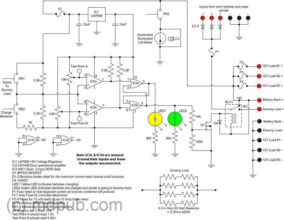
    Part of it requires a charge controller. I was wondring how difficult it would be to build the following and or how much it would cost to get it custom built.

    John

    chargecontrollerschematic.jpg


Comments

  • Registered Users, Registered Users 2 Posts: 3,862 ✭✭✭mikhail


    The components are relatively cheap - tens of euro plus whatever the batteries come to, I'd estimate (though I'm not sure about that volt meter). The real cost would be labour. I don't know what's typical, but I'd recommend getting a few quotes as it'll likely vary a good bit.


  • Registered Users, Registered Users 2 Posts: 1,806 ✭✭✭Poly


    you could build it on a breadboard or vero board fairly cheaply, maplin or radionics should have all the bits.

    Instead of the volmeter, you could just use your multimeter and save a few bob


  • Closed Accounts Posts: 6 heresjohnny


    Thanks guys,

    Have to admit im pretty much a complete noob to all this.

    This maybe a stupid question but I guess i
    -Get the board
    -Get the components
    -Solder the connections?

    John


  • Registered Users, Registered Users 2 Posts: 2,947 ✭✭✭D-Generate


    If you use breadboard then there is no need to solder. It is also much easier if it is your first time building a circuit as will teach you how to lay out circuits in an organised fashion.

    I suggest getting a breadboard, testing your circuit on that to make sure it works and then transfer it to Veroboard if it all works out. Veroboard is pretty cheap but breadboards cost a bit more but are reusable.


  • Registered Users, Registered Users 2 Posts: 3,862 ✭✭✭mikhail


    Yeah, breadboard makes circuit-building a bit like the big flat board you'd get in a lego set as a kid - you clip all the pieces into it to make your circuit, and if something's wrong, you can pull it out and start again. It's for prototyping.

    Stripboard (or veroboard as D-Generate called it) is what you transfer the final circuit onto and then solder.

    A quick google search should give you a decent idea what I mean.


  • Advertisement
  • Registered Users, Registered Users 2 Posts: 1,806 ✭✭✭Poly


    Hey Johnny. Do you have a discription of the circuit? What's the purpose of the dummy load?


  • Registered Users, Registered Users 2 Posts: 5,398 ✭✭✭DublinDilbert


    Dummy load is to dump the power being generated as the batteries are fully charged.

    Dummy load could be a heater and warm up water...


  • Registered Users, Registered Users 2 Posts: 1,134 ✭✭✭FarmerGreen


    Did anyone else spot the mistake in the circuit diagram?
    Hint-what happens when you push PB1?


  • Registered Users, Registered Users 2 Posts: 1,806 ✭✭✭Poly


    Did anyone else spot the mistake in the circuit diagram?
    Hint-what happens when you push PB1?

    burn the sh1te out of IC2?


Advertisement