Advertisement
Help Keep Boards Alive. Support us by going ad free today. See here: https://subscriptions.boards.ie/.
If we do not hit our goal we will be forced to close the site.

Current status: https://keepboardsalive.com/

Annual subs are best for most impact. If you are still undecided on going Ad Free - you can also donate using the Paypal Donate option. All contribution helps. Thank you.
https://www.boards.ie/group/1878-subscribers-forum

Private Group for paid up members of Boards.ie. Join the club.
Hi all, please see this major site announcement: https://www.boards.ie/discussion/2058427594/boards-ie-2026

Home heating automation

1155156158160161175

Comments

  • Registered Users, Registered Users 2 Posts: 4,784 ✭✭✭Roberto_gas


    Struggling to find EPH TR1/TR2 switch in Ireland…know anywhere we can get it ? or any other alternatives Thanks.


  • Registered Users, Registered Users 2, Paid Member Posts: 8,179 ✭✭✭deezell


    Try HeatMerchants. I've only seen it on UK sites, and even then it's hard to find. I think there's some alternative relay closure senders/receivers our there, I might have actually posted a link a while back. It's so hard to search my own posts though, I'll have a look back later.


  • Registered Users, Registered Users 2 Posts: 4,784 ✭✭✭Roberto_gas


    it asks for a trading login and merhcant ID ! I ordered it finally from heating controls online…


  • Registered Users, Registered Users 2 Posts: 4,784 ✭✭✭Roberto_gas


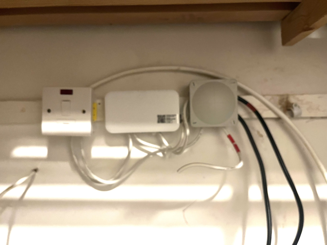
    Here is he WIP by local spark..he used junction box for each wiring..RF switch, cylinder thermostat and power wiring pending

    IMG_4647.jpeg


  • Registered Users, Registered Users 2 Posts: 1,307 ✭✭✭Technoprisoner


    im hoping someone here might be able to help me. We have a combi boiler and have google nest installed. All runs ok… the problem i have is that the old wall mounted thermostat still controls the heating in the sense that it is set to heat just the water and if i want to heat the radiators i have to get up and flick the switch on the old thermostat. Is there any way to make this system truely smart so that we can remotely switch between hot water or hot water and heat ??


  • Advertisement
  • Registered Users, Registered Users 2, Paid Member Posts: 8,179 ✭✭✭deezell


    A bit more detail. A thermostat with a switch? Maybe an image. Which Nest thermostat. Nest E or the Nest Learning. You have a Combi boiler. This provides HW direct to the tap without a cylinder. You don't have a cylinder then. Or maybe you do.. It's unclear what you have, I can't even hazard a guess, so post some images, a picture of the 'old thermostat' with the flickable switch. The nest thermostat and its receiver. The underside of the boiler. check the model name of the boiler. From there it's possible to deduce what way the whole thing was wired up, maybe.


  • Registered Users, Registered Users 2 Posts: 1,307 ✭✭✭Technoprisoner


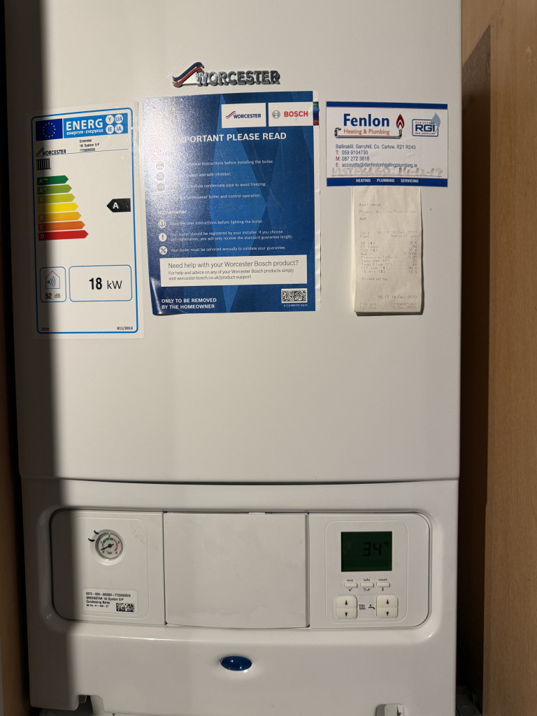
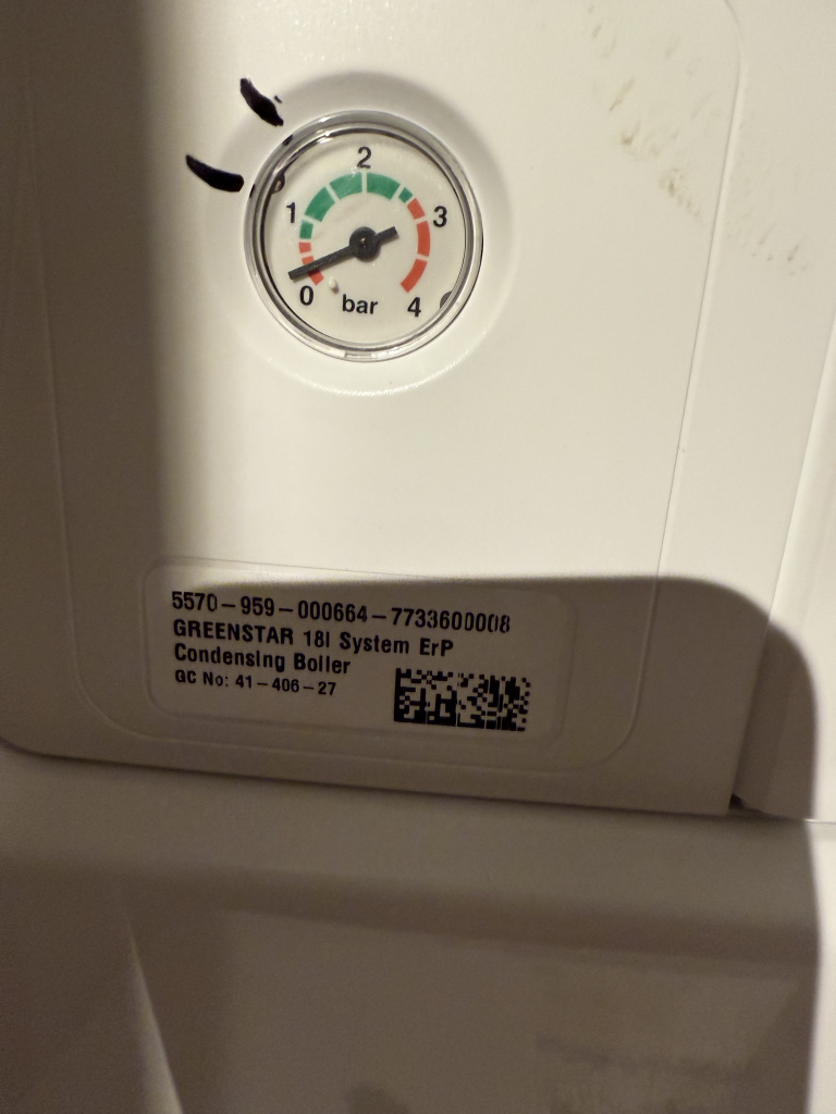
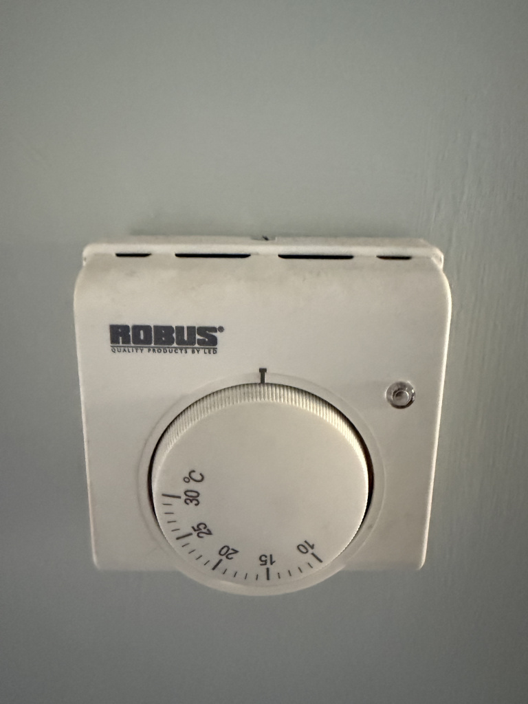
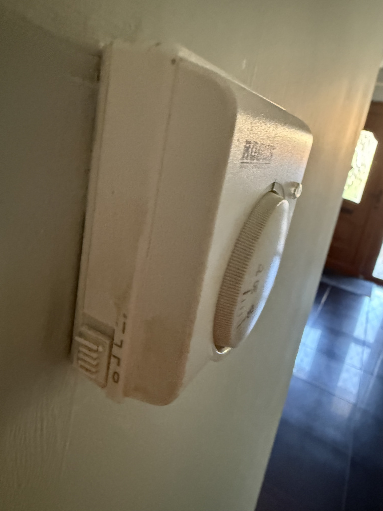
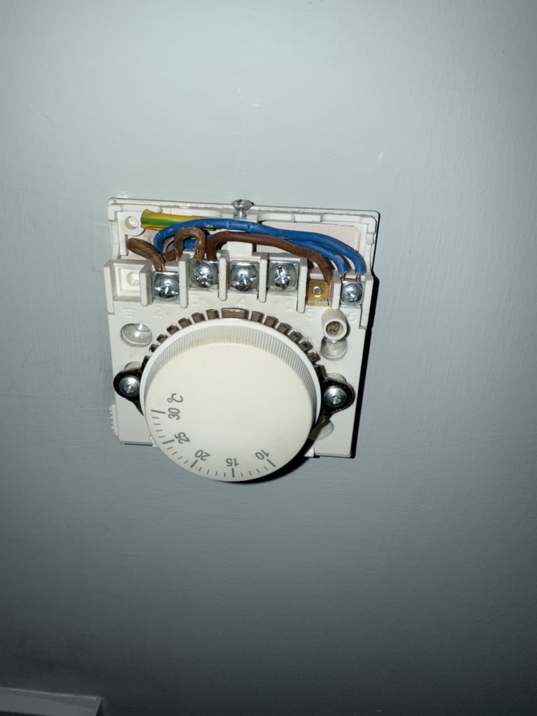
    sorry for the lack of info. I think we have a nest 3 learning. Ive attached a photo of the boiler and model number. And also a photo of the old thermostat and wiring. As for the cylinder im not sure. We have the normal hot water immersion tank in the hot press if thats what you are referring too. Sorry plumbing isnt something im very clued up on.

    IMG_1416.jpeg IMG_1419.jpeg IMG_1402.jpeg IMG_1403.jpeg IMG_1404.jpeg


  • Registered Users, Registered Users 2, Paid Member Posts: 8,179 ✭✭✭deezell


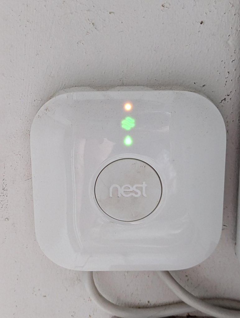
    It makes more sense now. Your boiler is a system boiler , but unless it had an optional diverter valve fitted, and separate HW cylinders pipes, its not working as a combi, it's safe to say it heats HW in the cylinder anytime it's fired. The installer on the sticker would confirm this. Did you have an old mechanical timer which was replaced by the Nest receiver? Can you spot that receiver? A small round battery receiver is Nest E, a square one powered by the mains is the Nest Learning or 3rd generation, with the fancier wall stat. The Nest learning has two relay switches, one HW, and one for CH, to facilitate two zone operation, but more of that later.

    I think your old system operated on an old mechanical timer, which fired the boiler, heated the HW and, if the Robus thermostat was turned up, and switched on, it also heated CH with HW. In this arrangement, you do not have a true two zone system, CH and HW, but more like a Zone and a half, HW only, or HW with CH. This is OK to a point. You can't control the temperature of the HW, but it will never get any hotter than the boiler set temperature on its panel when heating HW only. The Robus most likely controls a single zone valve to open the boiler hot flow to the radiators as well as the HW cylinder, which is always connected. I suspect the Nest was wired in place of the old timer, and while it can only fire the boiler based on the Nest stat schedule, it will not heat CH unless you switch the old Robus on, and have it turned up. See if you can spot the Nest receiver, probably close to the boiler. See if you have a motorised zone valve near the boiler, or in the cylinder area. I'll post an image of these, and will suggest a solution to your system when you confirm the above.

    NEST E Receiver

    s2co9le6lzm81.jpg

    NEST 3rd generation Heatlink Receiver

    na2oxaacid4b1.jpg

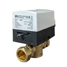
    Typical Motorised Zone Valve.

    images (2).jpeg


  • Registered Users, Registered Users 2, Paid Member Posts: 8,179 ✭✭✭deezell


    So if your system is as I've described, there is a solution. Systems where the HW always heats, but CH only heats when either a pump or a motorised valve is energised are often referred to as ' 'Gravity' fed. The earliest systems with back boilers or stoves would have an open and rising connection to the HW cylinder, so it would heat as soon as the boiler warmed up. Hot flow to the radiators would require a pump, so by putting the pump on a wall thermostat, you can switch CH in and out. A single timer was often used to fire the boiler. When dual zone timers became popular, it was obvious that two timer outputs, one for CH and one for HW, would not necessarily work when there weren't two seperate zone valves to switch the flow, or even one in a true gravity system.

    Many of these dual timers had a mode switch to enable gravity mode. In this mode, you would set both timers, CH and HW. Only the HW timer was connected to fire the boiler, but internally, the controller turned on the HW live out for either CH or HW timed events, so the boiler fired for either. The CH output also went live for CH events only, and this was connected to the CH pump, or zone valve in a pumped boiler system. This way, you could set timed events for either, with the provisio that HW would heat for either timer being on, but CH would only heat during a timed HW event.

    Now wiring in a dual timer with a gravity mode swith would require a minor rewiring of a legacy system like yours. The HW output would go to fire the boiler, the CH output would go to the old Robus stat to operate the zone valve or pump. The Nest learning Gen 3 is a dual output system, CH and HW. It doesn't have gravity mode though. The HW relay closes for HW events, the CH ditto.

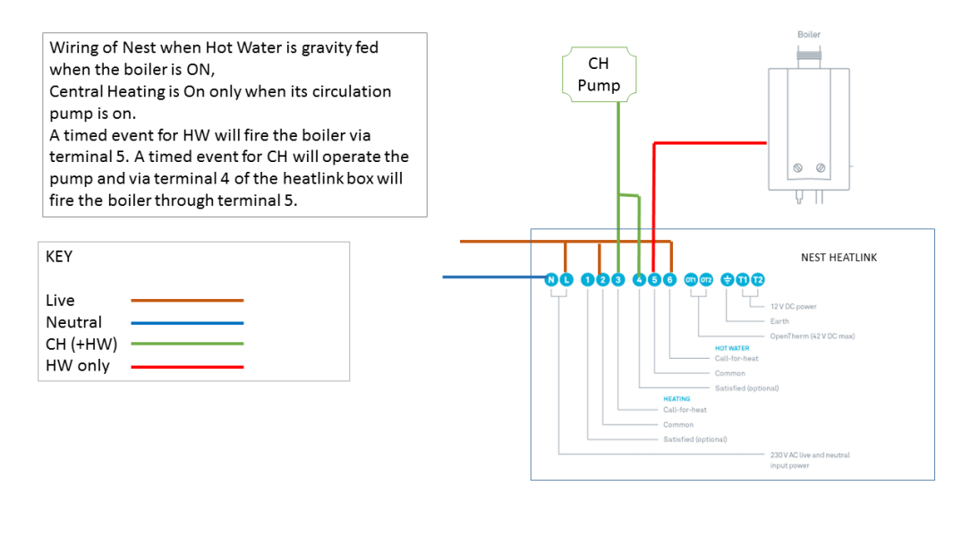
    There is however, a way of wiring the two pole relays to create gravity mode. This effectively sends live to the boiler for either CH/HW events, and live to the pump/zone valve for CH events only. I devised this diagram many years ago for a gravity style system like I suspect yours is. The Nest receiver is connected to the boiler by a slightly more complicated setof linked wires, and the CH live is sent to the old stat and from thee to what I've assumed is a CH zone valve. As the Nest room Thermostat now controls the CH demand, the old Robus is left turned up permanently, or removed and the live in and out bridged. You will need to get someone competent to sort out the wiring. The wiring of a two output controller to operate a gravity style system is not well know among plumbers/electricians, though I've seen since posts where others have figured this wiring arrangement for themselves. Have a look, it's diy doable by a person competent around wiring switches and fixed accessories. My diagram shows a pump, in your case this likely to be a motorised zone valve, but you shouldn't have to connect directly to this, just to the live that is currently being sent to the robus, which is probably already linked to the boiler live in the Nest receiver.

    Nest gravity HW.png


  • Registered Users, Registered Users 2 Posts: 1,307 ✭✭✭Technoprisoner


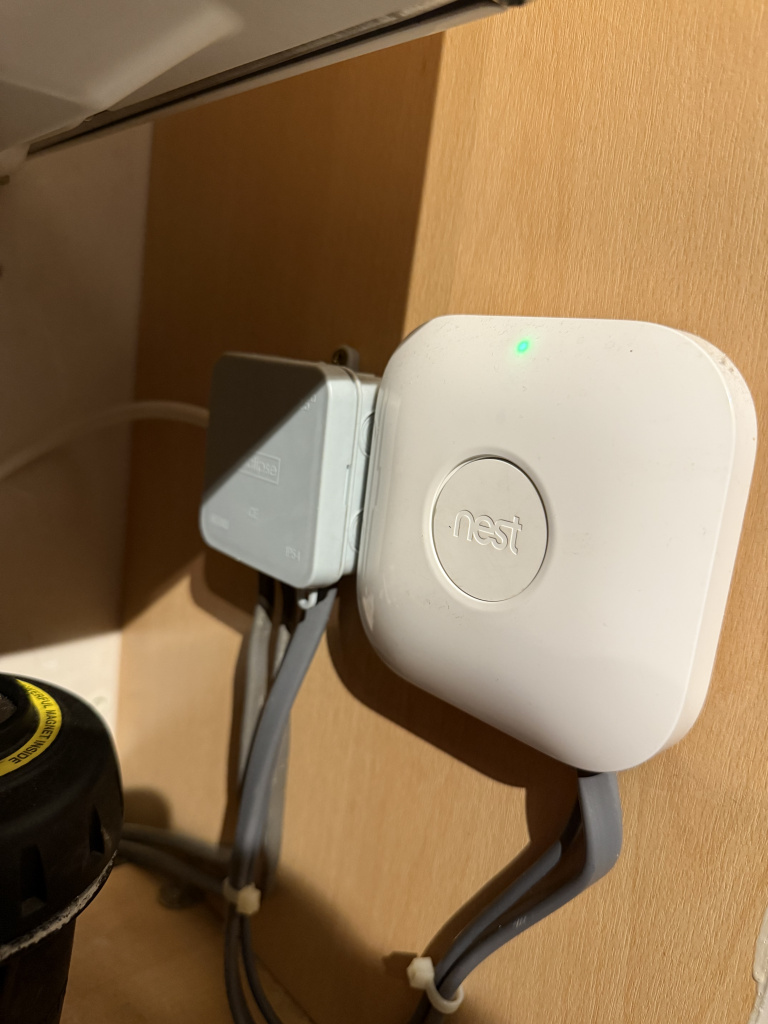
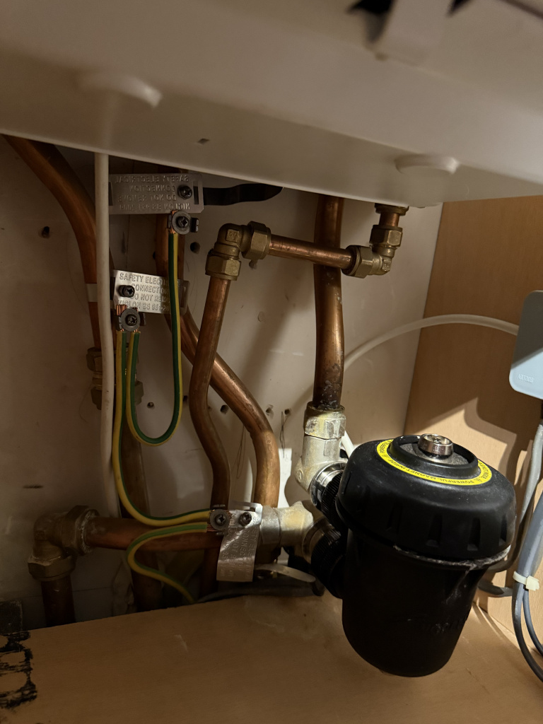
    thank you so much deezel. I think you are spot on but i will have to further confirm a few things. Im not afraid to do a bit of wiring .. i would just need to familiarise myself a bit before i start cutting and joining things 😂 ive attached a photo of the nest we have and the bottom of the boiler. I cant see a

    IMG_1437.jpeg IMG_1438.jpeg

    motorised zone valve unless its buried down underneath and behind the presses. I also dont see a pump anywhere so im going to presume its in around the back boiler system 🤷🏻 what my partner is telling me is that when the old boiler was replaced the nest was installed as well. So would i need to get a motorised zone valve to make it truelly smart ?


  • Advertisement
  • Registered Users, Registered Users 2, Paid Member Posts: 8,179 ✭✭✭deezell


    I'm assuming there is a valve, as the boiler contains a pump, which would circulate hot flow to the radiators as well as the cylinder, unless closed by a valve. The fact you can heat HW only by switching off the Robus indicates that you are stopping the hot flow to the rads but not to the cylinder. Was there a timer with the old boiler, perhaps it was part of it. This is a very common old setup. Timer to the boiler for everything, the a stat to operate the valve for ch. It's very likely that the live coming into the rebus is the live from the Nest to the boiler. If you have a phase tested or meter, you can check if live into the Robus goes on and off with the live from the Nest turning on the boiler. You mentioned a back boiler. Did this gas boiler replace another gas boiler or is this your first, and did/do you have a solid fuel back boiler also? If so, how are they operated together. It's really poor if the new boiler and Nest went in together, and no attempt was made to wire it to suit the fact that the Nest had the ability to control zones. The Nest is ideally designed to heat two zones using two motorised valves, CH and HW, but the presence of a back boiler complicates things, as generally you would have to leave the HW circuit always open without a valve if a back boiler was lit, and the cylinder didn't have seperate coils for heating HW by the gas boiler and the back boiler. It doesn't look great under there, you'll have to dig deeper to see what the Robus is controlling.


  • Registered Users, Registered Users 2 Posts: 1,307 ✭✭✭Technoprisoner


    sorry deezel as i explained plumbing and heating isnt something i fully understand. im wrong inmentioning a back boiler. I have been told that the old boiler did have a mechanical timer which was replaced with the nest when the boiler was changed and that the robus was used to switch between hot water and hw and heating. I may get the multi meter and check the live at the robus over the weekend to see if it powers up when the nest calls for the boiler. I would imagine it does. It would be amazing if we could have full remote control over the heating once and for all !! Is it a big job to get a motorised zone valve installed?


  • Registered Users, Registered Users 2, Paid Member Posts: 8,179 ✭✭✭deezell


    Not particularly, but you may already have it somewhere, perhaps in the hot press with the cylinder. How else can you get HW only heating. The biggest challenge to fitting zone valves in not the plumbing, it's the wiring from the thermostat receiver to the valves, and in the case of a two valve system, the relays built into the valves have to be utilised to fire the boiler, so each valve has to jointly send a live to the boiler to fire from these relays. This can often mean adding extra cables from boiler location to valve location to hotpess, which is quite a task in a two story house, not so bad in a bungalow.


  • Registered Users, Registered Users 2 Posts: 4,784 ✭✭✭Roberto_gas


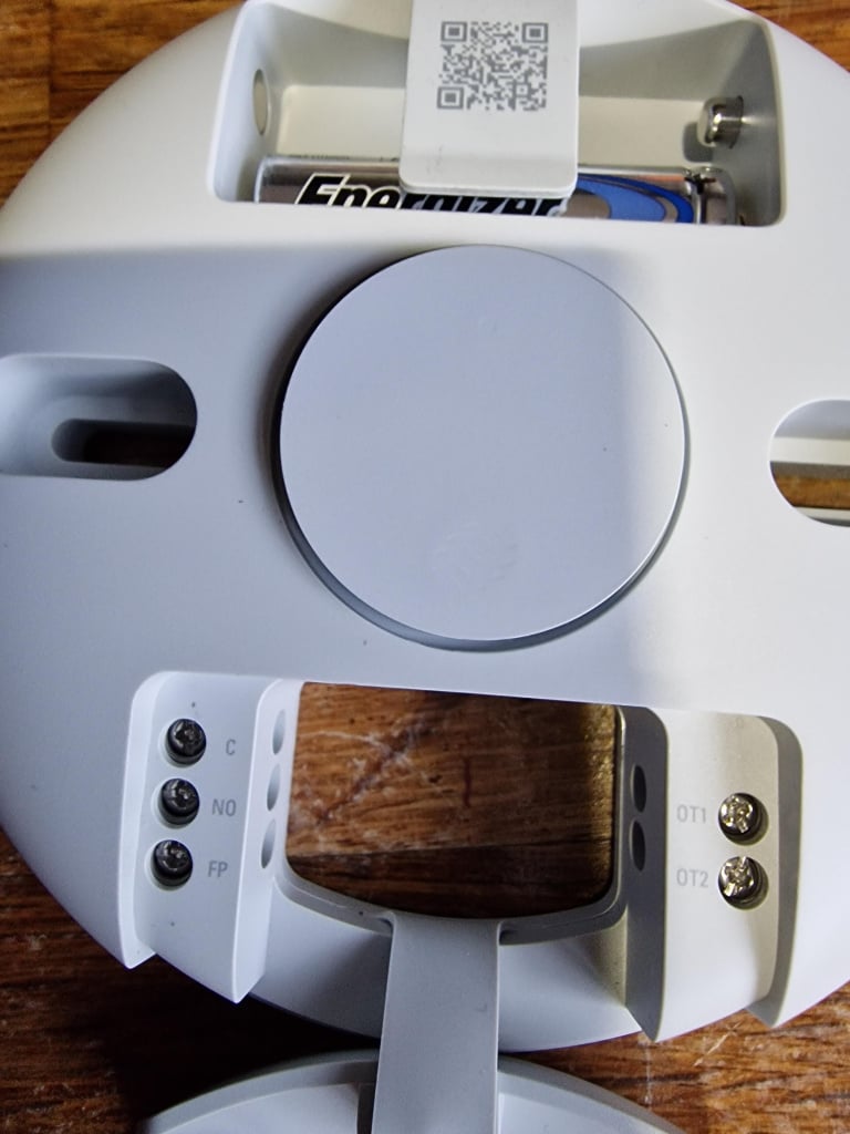
    Just finishing the final steps….is this the ckt to be used for wiring TR1 and TR2 RF switch ? From hotpress to boiler to switch it on ?

    image.png


  • Registered Users, Registered Users 2, Paid Member Posts: 8,179 ✭✭✭deezell


    Yes, from hot press to either Boiler directly, or HW zone valve if you have a zoned system. The HW zone valve then fires the boiler. If you have HW timing on your system receiver or controller, then the HW switched Live from this is connected to C on TR2, not the permanent live link from the power supply live to TR2 as shown in the diagram.


  • Registered Users, Registered Users 2 Posts: 4,784 ✭✭✭Roberto_gas


    timer switch on boiler so assume its direct replace with TR2?


  • Registered Users, Registered Users 2, Paid Member Posts: 8,179 ✭✭✭deezell


    Sorry, I had to look back and find all the posts to have a quick scan/read. If I'm correct, you got two zone valves installed for independent HW and CH, and a Tado wireless stat with extension kit to switch the zone valves on using the app. What you didn't get was the last piece of wiring from the zone valves' relays to the boiler switched live in, so that either zone valve would fire the boiler. The TR21/TR2 kit removes the need for having to conduit cables from the zone valves location in the hotpress to the boiler. So firstly, ignore all my comments in the previous reply, I'd no recollection of your particular system till I reread it, so I was barking up a different tree.

    So, you need to send the call for boiler from the joint outputs of the zone valve relays to the boiler switched Live input. Hopefully, these relay outputs are terminated in a wiring box next to the zone valves. The relay outputs are volt free, and the Common and Normally open wires are the Orange and Grey wires in the zone valve cables. Both Orange wires should have permanent live connected, and both Grey wires are joined, and connected to the Lin of TR1. Either valve will then trigger TR1 when the HW or CH look for heat. TR2 is connected to the boiler in place of the old Timer, as per the TR2 Diagram. This is the final step, any timed event on the Smart stat, either for HW or CH, will open their respective zone valve and cause the boiler to fire. Forget my previous comments, I'd forgotten the details, mixing them up with something else.


  • Registered Users, Registered Users 2 Posts: 4,784 ✭✭✭Roberto_gas


  • Registered Users, Registered Users 2 Posts: 4,784 ✭✭✭Roberto_gas


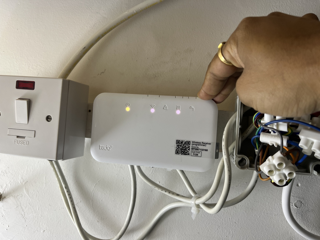
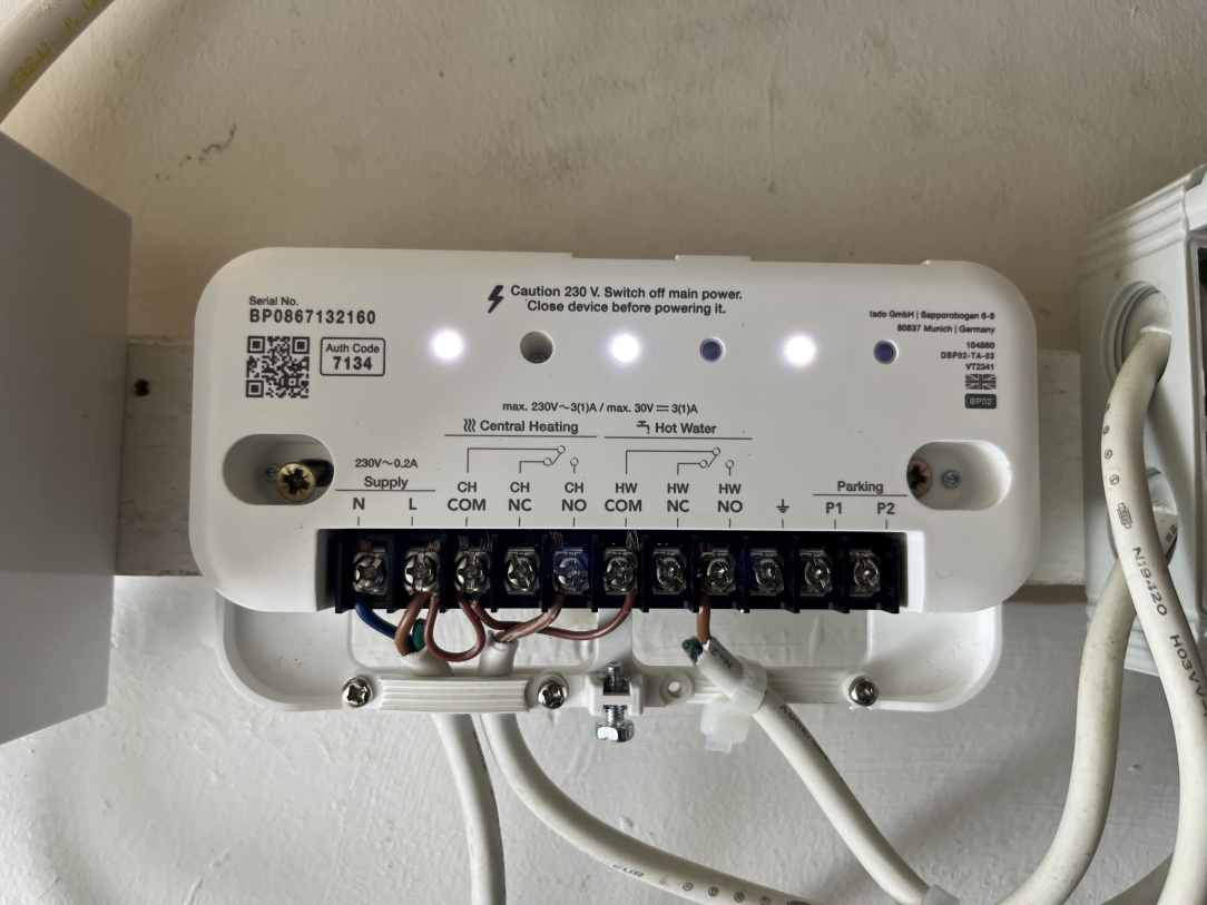
    image.jpg IMG_4746.jpeg IMG_4747.jpeg

    struggling with changing configuration mode(stuck at yellow)and hot water is not working while testing..any advice whats wrong..CH is getting fired alright


  • Registered Users, Registered Users 2, Paid Member Posts: 8,179 ✭✭✭deezell


    Have a look here, though it's a relatively older installation manual, it should still work. It gives the step to enable the HW schedule tab in the App. This in turn should use the ext kit device.

    https://drive.google.com/file/d/1KEBB33uHLzF9ib7MnSTgx_T2UI1-Olcx/view?usp=drivesdk


  • Advertisement
  • Registered Users, Registered Users 2 Posts: 4,784 ✭✭✭Roberto_gas


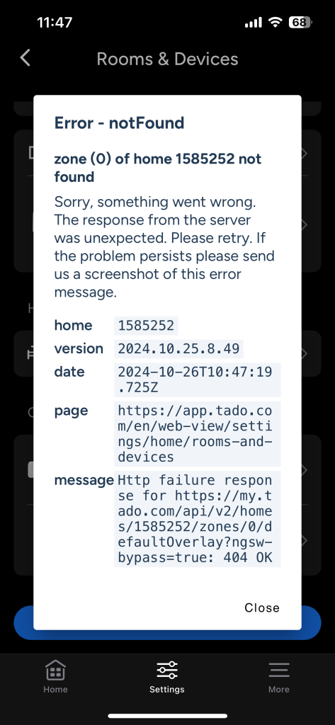
    thr is no hot water tab in my app? I added the receiver..it was there previously but gone once i got this error

    IMG_4745.png

    EDIT i added reciver again and hot water is there now in app but still nothing on receiver


  • Registered Users, Registered Users 2 Posts: 4,784 ✭✭✭Roberto_gas


    sorted the test mode is on now thru thermostat thanks deezel !!


  • Registered Users, Registered Users 2, Paid Member Posts: 8,179 ✭✭✭deezell


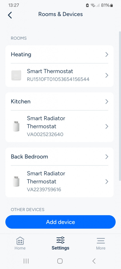
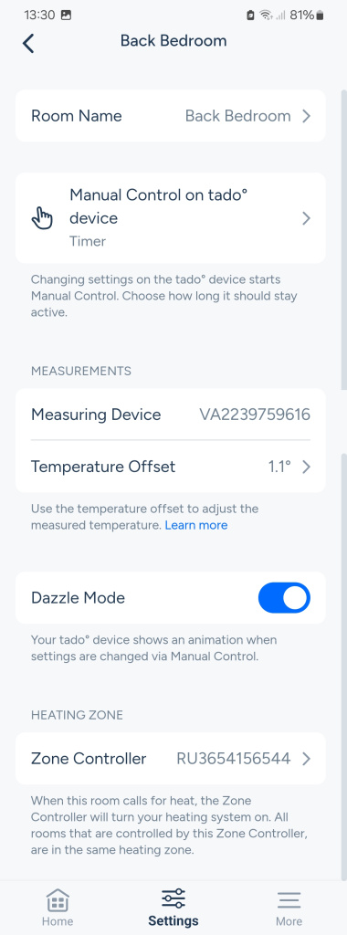
    In the Settings, Does HW list under Rooms and Devices. What controller is showing for the HW. I assume it should be the ext kit. I don't have an extension kit for comparison, but each 'Room' or zone is associated with the device which fires the boiler on its behalf, and can also have a measuring device if temperature control is involved. E.g, a TRV may use its own temperature reading, or the main stat or a wall sensor stat, and it's controller to fire the boiler will be the wired stat or wireless/extension kit relay

    Room/device list

    Screenshot_20241026_132732_tado.jpg

    And settings for a Room/device

    Screenshot_20241026_132958_tado.jpg


  • Registered Users, Registered Users 2, Paid Member Posts: 8,179 ✭✭✭deezell


    Ah

    Ah great! It's always something small,but irritating nonetheless. I've just spent two weeks and read dozens of pages of tech advice and configuration examples to try and get 4G voice calling on my new Sky Mobile Sim. In this case there's no solution, Sky have genuinely fkd up at launch. Maybe Roy Keane might have a word with them...


  • Registered Users, Registered Users 2 Posts: 4,784 ✭✭✭Roberto_gas


    I am still not clear how the room thermostat/App/Smart TRVs interact to make a call to boiler through valves. I was clicking hot water on off on the APP and it was not doing anything on the receiver or zone valve. similarly CH was not getting on or off on receiver thru App TRVs etc...It was only working thru test switches…sorting RF switches so will check again tomorrow


  • Registered Users, Registered Users 2, Paid Member Posts: 8,179 ✭✭✭deezell


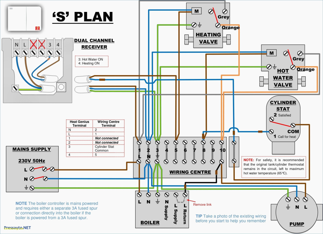
    I thought you had someone wire up the zone valves to a wiring centre/terminal strip in a box. Those white wires to the CH NO and HW NO should go to the Zone valves' Actuator motors live in, usually the brown wire in the valve cable. The valves also require a link from neutral to their blue wires to complete the Actuator circuit. Also, check that the valves have not been locked in the open position, necessary if you've been using CH without the valves wired up, there's a little lever on the Actuator box that manually opens the valve and can be clicked into a notch to lock it open. Permanent live should also be connected to the valves' Grey wires, this is connected to the Orange wires by the valves' relay switches when the valves open, and both Orange wires are sent to the boiler to fire it, directly, or in your case via the TR1/TR2.


  • Registered Users, Registered Users 2, Paid Member Posts: 8,179 ✭✭✭deezell


    Generic S plan 2 Zone wiring, with cylinder stat.

    114942f42cba3ed64c65a45013749708.jpg


  • Registered Users, Registered Users 2, Paid Member Posts: 8,179 ✭✭✭deezell


    Re reading your post, when you say 'valves' are you referring to the Zone valves or the TRVs? TRVs will be linked on the app by default to the CH relay in the main stat, as this is the only 'Zone Controller' for CH, but check in your App configuration if you're adding TRVs that this happens, see my screen grab two posts up for a bedroom TRV). Sometimes TRVs are installed just to give programmable temperature control to a room while the main stat is calling the boiler, without the ability to call the boiler itself. In this case the Zone Controller for a TRV is blank.


  • Registered Users, Registered Users 2 Posts: 4,784 ✭✭✭Roberto_gas


    well lets put it mildly whoever is putting it as a spark is learning it on the go😅😅..wiring has been a challenge😃..yes wiring is as per the diagram u shared and valves are getting powered thru receiver test button. Valves are zone valves in my msgs

    My point was how does the system work

    1. Wireless thermostat controls the trigger to boiler and valves for CH or smart TRVs can? (how to configure these or what options are there?)
    2. The wireless thermostat can trigger hot water thru HW valve and signal to boiler or hot water can be started using App which sends signal to Valve thru receiver and finally boiler..

    thanks


  • Advertisement
  • Registered Users, Registered Users 2, Paid Member Posts: 9,701 ✭✭✭10-10-20


    Oh that's very good. Must rob borrow that for my toolbox.


Advertisement