Advertisement
If you have a new account but are having problems posting or verifying your account, please email us on hello@boards.ie for help. Thanks :)
Hello all! Please ensure that you are posting a new thread or question in the appropriate forum. The Feedback forum is overwhelmed with questions that are having to be moved elsewhere. If you need help to verify your account contact hello@boards.ie

Amiga CD32 - One niggle remains....

  • 28-05-2025 05:45PM
    #1
    Registered Users, Registered Users 2 Posts: 8,059 ✭✭✭


    Most certainly my final CD32 thread, and for anyone who remembers the previous ones (first thread was just some maintenance in the form of a recap, and the second one was bringing the machine in line with more powerful Amigas by adding some upgrades), I kinda felt I was finished with this console. It dawned on me after the upgrade thread though, that while the expansion board is certainly brilliant, there's one minor 'flaw'. The expansion board offers RGB out, and thereby, if I ever wanted to play some of the CD based games (some of which offer cd music etc compared to the WHDload versions by using the expansion, I'm back to using the pretty poor composite output from the stock machine.

    Well, that can be remedied by adding some gubbins under the shell to give me native RGB out for CD based games, and then if using the expansion, I'd has its own RGB out - so the best of both worlds.

    1748363077973.jpg

    ^^ Now, given the more niche nature of the CD32, there isn't the availability of wonderful open source pcb designs to help with this mod. We're back to doing things the old fashioned way here, with bare components. Given that, I said I'd try to make it look somewhat decent by using a section of prototyping board for most of the passive components. The above features x4 470uf capacitors, in line with x4 75ohm resistors accordingly. These will be the video components of the board, so one line for Red, one for Green, one for Blue, and one for Composite Sync. The components shown above aren't soldered in yet, so look at bit wibbly wobbly.

    1748363077962.jpg

    ^^ Soldered into place now, and straightened up a bit.

    1748363077952.jpg

    ^^ I scored the prototype board where I wanted to snap it, and then snapped it accordingly. I added resistor legs then from the resistors to the entry pads (which later on it'll be seen I need not have bothered.)

    1748363077940.jpg

    ^^ Before doing anything, a quick power on and test is in order. I always try to do this where possible to ensure things are working prior to undertaking any work.

    1748363077932.jpg

    ^^ Yep, perfect. This is through the expansion so it's already in RGB, but at least I know the machine is working. Time to crack on.

    1748363077920.jpg 1748363077906.jpg

    ^^ Onto the table, and opened up. I'm always impressed by this board, it's so compact but squeezes so much in.

    1748363077898.jpg

    ^^ So, the RF modulator is the area of interest for this mod. Suffice to say, using RF won't ever be happening, so instead of a destructive/drilling holes in the shell mod, I'll remove the modulator and use the space that's there. This mod is completely reversible, and should the bizarre need ever arise, the RF modulator can be switched back in instead of the RGB mod.

    1748363077889.jpg

    ^^ RF modulator removed, and we've a nice bit of space to work in, that has a good sized opening in the shell. No cutting at all needed.

    1748363077881.jpg

    ^^ I bought a set of VGA connectors to use for the mod, the female connector will be placed inside the Amiga, while the male end will go on the scart cable later on.

    1748363077873.jpg 1748363077865.jpg

    ^^ These connectors, while being a little bulky, do offer a nice screw-in type installation method for the wiring, cutting down on soldering.

    1748363077855.jpg

    ^^ On the underside however, there's some soldered pins which prevent the board sitting flush inside the Amiga.

    1748363077848.jpg

    ^^ A snip snip here….

    1748363077840.jpg

    ^^ …and a Dremel Dremel there…..gives us a much flatter side to place the board down inside the Amiga.

    1748363077832.jpg

    ^^ A little test fit - yeah, this seems a decent option to use. It fits nice, there's room for wiring too…..BUT….securing it to the Amiga board is going to need some measurement etc.

    1748363077819.jpg

    ^^ First thing first, I insulate the area so there's no shorts between the Amiga and the VGA connector.

    1748363077806.jpg

    ^^ I line up the VGA connector to where I think it fits best in context of the outer shell.

    1748363077795.jpg

    ^^ I then outline the VGA board onto the tape with some pen. From here, I can identify where and how to secure the boards together.

    1748363077781.jpg

    ^^ So three of the mounting points used for the RF modulator, more or less line up with these spots on the VGA board. I've removed the solder mask here with a fibre glass pen. If I can get the board soldered in these three spots, it SHOULD ne nice and secure for cable insertion/disconnection purposes.

    1748363077765.jpg

    ^^ The three holes inside the pen markings are the holes I'll be using.

    1748363077749.jpg

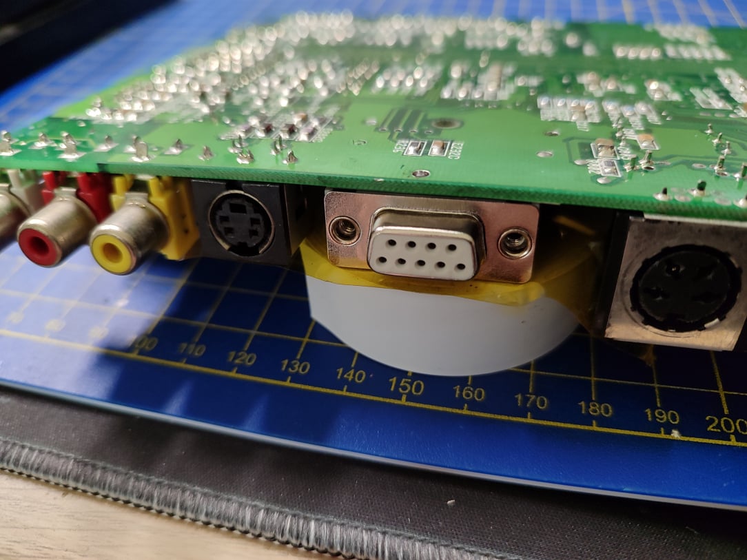
    ^^ I line up the VGA connector, secure it in place good enough to turn it upside down for soldering.

    1748363077730.jpg

    ^^ And then I use a brace underneath to keep some pressure on the VGA connector, to ensure it's as flat as possible.

    1748363077713.jpg

    ^^ The three points are now soldered. In my haste, I hadn't noticed the larger of the three holes isn't a plated one, it's just a hole in the pcb….so I had to add a resistor leg to that and then brace it against a ground point. It seems quite solid, so I think it'll be fine like this.

    1748363077701.jpg

    ^^ Yep, it's rock solid after a few test fits of the male connector. The pen ink has ran due to the cleaning IPA used, but it's not needed now so it's not an issue. You can see by the marks that are left on the tape, I brought the VGA connector foreword a little to give me more anchoring options.

    1748363077655.jpg

    ^^ Ok, onto the wiring next. From here I'll need to secure the video prototype pcb, but I notice it stands very tall inside the console….so much so, that the shielding doesn't fit on. Damn.

    1748363077641.jpg

    ^^ However, if I flip it upside down, the caps sit into a nice groove, the board sits lower overall, and the shielding fits back on without contacting the proto pcb. Nice, this is the way.

    1748363077636.jpg

    ^^ Taking no chances here, I insulate the space where the caps will fit into, and I insulate the caps themselves. Two layers should kapton should be more than enough.

    1748363077625.jpg

    ^^ I then anchor the prototyping pcb into place using resistor legs and a ground point on the board

    1748363077618.jpg

    ^^ And one on this side too. So two anchor points, and the board is going nowhere.

    1748363077606.jpg

    ^^ Ok, time to start wiring. I tin the cables I'll use for R, G, B, & Sync. I'd prefer working with thinner cable than this, but my thinking is the thicker insulation on this cable will help reduce any intereference.

    1748363077600.jpg

    ^^ Blurry pic apologies. We'll tap the signals directly from the video encoder pins, the Sony CXA1145M

    1748363077591.jpg

    ^^ Done, RGBS all wired from the video chip, to the prototype board resistors, through the caps, and ready for output wiring to the vga connector.

    1748363077572.jpg

    ^^ Output wiring for RGBS now done.

    1748363077562.jpg

    ^^ The orange wire provides 5v for RGB Blanking, and telling the TV to display the RGBS signals. It comes from resistor 4R7 on the board, and we put it through a 100ohm resistor before going intot he VGA connector (I forgot the resistor in the above pic, but realised it later on when I'd a resistor left over!)

    1748363077529.jpg

    ^^ Next we add a 1000ohm resistor onto a cable. We need to supply 12v to the VGA port. This is then fed into the scart cable, up into the tv, and tells the TV to switch to the Scart channel and use 4:3 automatically.

    1748363077496.jpg

    ^^ Ok so far on the left of the VGA connector, we have RGB & Sync, and on the right side of the connector, we have 5v and 12v fed in.

    1748363077481.jpg

    ^^ Now we need stereo audio, so we tap it from the two audio caps here. The left cap as we're looking at it is the Right channel, and the right cap is the Left channel….

    1748363077470.jpg

    ^^ These audio cables then go through a 75ohm resistor each before passing into the vga connector.

    1748363077459.jpg

    ^^ Stereo audio cables now wired in. It's getting busy here with wires, and given the wiring here (the thickness for interference reasons, and the compact board with power components everywhere, it's hard to keep things neat really.)

    Also above you can see I've added a brown wire on the left hand side, this is simply a ground connection. The VGA connection is grounded anyway by reason of soldering it to the old RF modulator mount points, but adding a dedicated ground cable is no harm anyway.

    1748363077447.jpg

    ^^ That's the wiring done anyway. It's not pretty, but should be functional. There's nine connections needed:

    1. Red
    2. Green
    3. Blue
    4. Composite Sync

    G. Ground

    5) 5v

    6) 12v

    7) Unused (purposely left a gap to reduce any intereference on the audio cables next door)

    8) Audio Right

    9) Audio Left

    1748363077433.jpg

    ^^ Time for some surgery on a scart cable. We need to make a dedicated cable for this Amiga, with the VGA male connector on the one end.

    1748363077424.jpg

    ^^ The Scart end is snipped off of one end, and then you simple continuity probe the scart end against the snipped wires to see which cable corresponds to the needed pins. We need the nine pins mentioned above.

    1748363077415.jpg

    ^^ All done. Once you've identified say the Red cable, you know that's pin 1 on the female end of the vga connector as that's how we wired it, so it's automatically pin 1 on this end too.

    1748363077404.jpg

    ^^ All done, quick and easy.

    1748363077395.jpg

    ^^ Reassembling now, you can see the shield has a nice gap to the new wiring underneath. It's all insulated again too, just incase.

    1748363077383.jpg

    ^^ Visually, it actually looks nice this way. It's slightly uneven on one side, but that's as flat to the Amiga board as I could get it without risking exposing more copper and the further risk of shorts etc. For a connector that'll likely NEVER be used, I'm fine with it!

    1748363077372.jpg

    ^^ Ok, time to test now with no expansion board in, and simply using this new RGBS output instead for CD based games.

    1748363077354.jpg

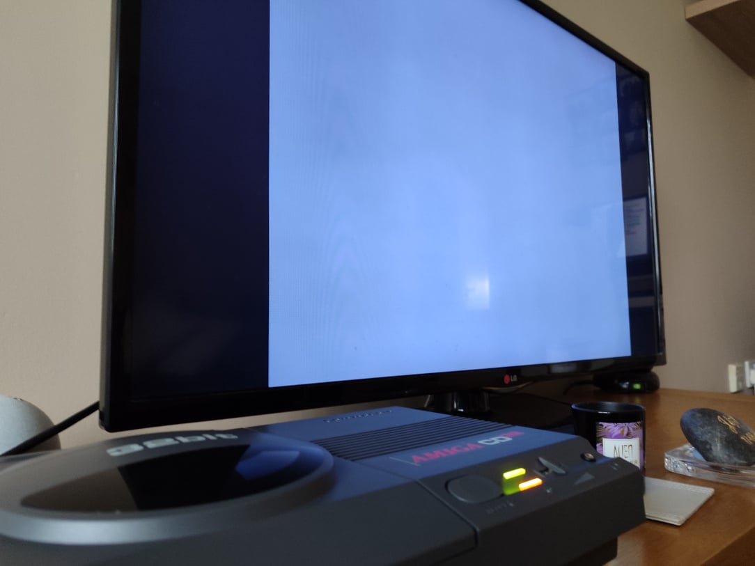
    ^^ Ok it's doing something….

    1748363077338.jpg

    ^^ Sweeeet, it works! A nice, crisp, RGB image from the stock machine.

    1748363077322.jpg

    ^^ Forgive the crappy phone pics which make it look quite soft, but it's a nice vivid picture in person. I've seen better rgb images, but I've seen much worse too.

    1748363077306.jpg

    ^^ Time to check how games look with my totally legit copy of D/Generation…

    1748363077289.jpg

    ^^ It spins…

    1748363077274.jpg

    ^^ It reads…

    1748363077258.jpg

    ^^ Quite sharp!

    1748363077241.jpg

    ^^ The dithering is inherent int he game, doesn't look amazing, but the pixel sharpness, colours, and vibrancy are all on point.

    1748363077225.jpg

    ^^ You can kinda see how sharp the text is now. There's a text-shadow happening but that was just how my phone picked it up, wasn't visible in person.

    1748363077213.jpg

    ^^ All done.

    1748363077201.jpg

    ^^ Beauty shot to close.

    That'll definitely conclude my Amiga CD32 threads (I promise!)


Comments

Advertisement