Advertisement
If you have a new account but are having problems posting or verifying your account, please email us on hello@boards.ie for help. Thanks :)
Hello all! Please ensure that you are posting a new thread or question in the appropriate forum. The Feedback forum is overwhelmed with questions that are having to be moved elsewhere. If you need help to verify your account contact hello@boards.ie

Non Priority Shower Unit explained

Options
  • 03-01-2021 10:55pm
    #1
    Registered Users Posts: 6,250 ✭✭✭


    I have an old non priority shower unit that I'm looking to figure out.

    I know what the MCB's are and the ESN240B's are but I'm not sure what the two on the right are, the Doepke RLR1's

    Can someone explain what they are and their purpose please?
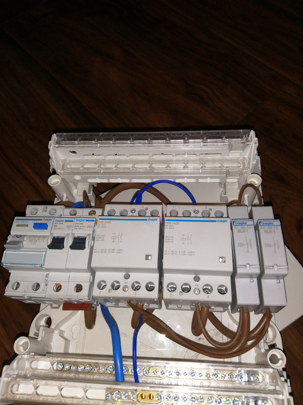

    IMG-20210103-215331.jpg

    Larger image https://postimg.cc/nsqP8Ggt


Comments

  • Banned (with Prison Access) Posts: 124 ✭✭Treseemme.


    They're current sensing relays

    Each shower is wired through one and when shower is turned on they break the supply to the other showers contactor coil


  • Registered Users Posts: 6,609 ✭✭✭zg3409


    The way these systems work is:

    Both showers get power all the time.
    Both large middle contactor's are on 24/7/365

    Once any shower draws any significant amount of power its current sensor (one of the 2 on the right) detects one of the shower is on. Based on this it powers off the other shower (by powering off its contactor) until the person turns off the shower later.

    The Hager contactor's tend to give trouble as they overheat and melt inside as they are on always and there are 2 right next to each other in an enclosure. If you replace them the new ones fail too. Ideally they need lots of air around each contactor and not next to each other.

    When you say figure out, what are you trying to do? These are high power and a fire risk due to heavy loads. What would you like to achieve?


  • Registered Users Posts: 6,250 ✭✭✭Buford T Justice


    I'm looking to see if I can repurpose some things that I have for my campervan build (see sig).

    As per the crude diagram below, I will have two 240 sources of power for my van, the first being an inverter running off 12v batteries and the second being shore power plugin.

    Under normal circumstances (ie no shore power) the inverter will provide power to the sockets. However, if I plug in shore power, I want the contactor to switch over automatically to use the shore power to provide the power and disconnect the shore power. Bearing in mind this is for a campervan, there won't be massive loads running through this. At the moment it's only a fridge

    I know I can get a Schneider contactor to do this, but I'm hoping to re-use things that I already have.

    IMG-20210104-174438.jpg


  • Registered Users Posts: 6,609 ✭✭✭zg3409


    I'm looking to see if I can repurpose some things that I have for my campervan build (see sig).

    As per the crude diagram below, I will have two 240 sources of power for my van, the first being an inverter running off 12v batteries and the second being shore power plugin.

    Under normal circumstances (ie no shore power) the inverter will provide power to the sockets. However, if I plug in shore power, I want the contactor to switch over automatically to use the shore power to provide the power and disconnect the shore power. Bearing in mind this is for a campervan, there won't be massive loads running through this. At the moment it's only a fridge

    I know I can get a Schneider contactor to do this, but I'm hoping to re-use things that I already have.

    IMG-20210104-174438.jpg

    I believe to meet the regulations you need either a mechanical switch to change supplies or an electrically and mechanically interlocked contactor. The contactor's above won't do what you need. A simple 2 position 2 pole switch would be best. If you are looking at automated chageover you need to be 100% sure there is no chance you will supply power from your inverter system back to the caravan site in case of any fault or during a power cut. This can kill someone else nearby. Buy a proper 2 contactor mechanically interlocked system with auxiliary contacts if you need this set up, like this but with 240v AC contacts and an AC or DC coil as you need:

    https://ie.rs-online.com/web/p/contactors/6097432/?cm_mmc=IE-PLA-DS3A-_-google-_-CSS_IE_EN_Automation_%26_Control_Gear_Whoop_HI-_-(IE:Whoop!)+Contactors+(2)-_-6097432&matchtype=&pla-478525856838&gclid=Cj0KCQiAlsv_BRDtARIsAHMGVSbZ-KBUl6GikaBQXIyGlJRYjYjApNGZJ-6bIPZM6HwmgIt0F_9lGncaAnROEALw_wcB&gclsrc=aw.ds


  • Registered Users Posts: 6,250 ✭✭✭Buford T Justice


  • Advertisement
  • Registered Users Posts: 6,609 ✭✭✭zg3409


    You need 2 contacts mechanically connected so they both never be in at the sane time. You also need normally closed auxiliary contacts, . These are wired so electrically both can't be on at the same. These rules are to protect others.


  • Banned (with Prison Access) Posts: 124 ✭✭Treseemme.


    zg3409 wrote: »
    The way these systems work is:

    Both showers get power all the time.
    Both large middle contactor's are on 24/7/365

    Once any shower draws any significant amount of power its current sensor (one of the 2 on the right) detects one of the shower is on. Based on this it powers off the other shower (by powering off its contactor) until the person turns off the shower later.

    The Hager contactor's tend to give trouble as they overheat and melt inside as they are on always and there are 2 right next to each other in an enclosure. If you replace them the new ones fail too. Ideally they need lots of air around each contactor and not next to each other.

    When you say figure out, what are you trying to do? These are high power and a fire risk due to heavy loads. What would you like to achieve?

    That was the weird thing about those units

    The n/c contact on the sensing relay and the main contactors permanently energized

    Not the greatest design


  • Banned (with Prison Access) Posts: 124 ✭✭Treseemme.


    The Rcd is or should be the isolator for the board

    May not be obvious there


  • Registered Users Posts: 6,250 ✭✭✭Buford T Justice


    zg3409 wrote: »
    You need 2 contacts mechanically connected so they both never be in at the sane time. You also need normally closed auxiliary contacts, . These are wired so electrically both can't be on at the same. These rules are to protect others.

    Just trying to understand. Why would the contactor that I posted not work? I've seen a few people use them in their own installs. If it's switching both contacts when energised then there'd be no risk of the inverter back feeding the shore power in case of a power failure on the shore power since it'd be routing to the onboard power. It'd be done in the case of four in and two out. Perhaps my diagram is insufficient to describe this.


Advertisement