Advertisement
If you have a new account but are having problems posting or verifying your account, please email us on hello@boards.ie for help. Thanks :)
Hello all! Please ensure that you are posting a new thread or question in the appropriate forum. The Feedback forum is overwhelmed with questions that are having to be moved elsewhere. If you need help to verify your account contact hello@boards.ie
Hi there,
There is an issue with role permissions that is being worked on at the moment.
If you are having trouble with access or permissions on regional forums please post here to get access: https://www.boards.ie/discussion/2058365403/you-do-not-have-permission-for-that#latest

Central Heating Circ Pumps Power Factors

  • 12-11-2020 9:01am
    #1
    Registered Users, Registered Users 2 Posts: 3,623 ✭✭✭


    I was looking at a very old Grundfos Selectric circulating pump label and saw the corresponding watts/amps will equate to a PF of 1.0 or very close, ie 105W/0.42A, 70W/0.28A & 40W/0.17A (all at 240V) which equate respectively to PFs of 1.04, 1.04 & 0.98, My own, a old Salmson gives calculated PF of 1.
    I installed a A rated Wilo circ pump 2 years ago and while this is a variable speed motor in all modes the PF is ~ 0.53 which I would have expected for a fractional HP motor?, this pump motor only consumes ~ 40% of the old pump.
    Can someone give a explanation for the high PFs in those old pump motors?.


Comments

  • Moderators, Home & Garden Moderators, Technology & Internet Moderators, Regional East Moderators Posts: 12,641 Mod ✭✭✭✭2011


    John.G wrote: »
    I was looking at a very old Grundfos Selectric circulating pump label and saw the corresponding watts/amps will equate to a PF of 1.0 or very close, ie 105W/0.42A, 70W/0.28A & 40W/0.17A (all at 240V) which equate respectively to PFs of 1.04, 1.04 & 0.98, My own, a old Salmson gives calculated PF of 1.

    There may be a capacitor within this motor that is correcting the power factor.
    I installed a A rated Wilo circ pump 2 years ago and while this is a variable speed motor in all modes the PF is ~ 0.53 which I would have expected for a fractional HP motor?

    I haven’t seen a power factor this bad for any motor. Does it state this on the motor name plate or data sheet? Or how do you know this?
    this pump motor only consumes ~ 40% of the old pump.

    Maybe it is more efficient and / or maybe it is moving less water.


  • Registered Users, Registered Users 2 Posts: 5,374 ✭✭✭aido79


    John.G wrote: »
    I was looking at a very old Grundfos Selectric circulating pump label and saw the corresponding watts/amps will equate to a PF of 1.0 or very close, ie 105W/0.42A, 70W/0.28A & 40W/0.17A (all at 240V) which equate respectively to PFs of 1.04, 1.04 & 0.98, My own, a old Salmson gives calculated PF of 1.
    I installed a A rated Wilo circ pump 2 years ago and while this is a variable speed motor in all modes the PF is ~ 0.53 which I would have expected for a fractional HP motor?, this pump motor only consumes ~ 40% of the old pump.
    Can someone give a explanation for the high PFs in those old pump motors?.

    It's not possible to have a power factor greater than 1.
    What calculations are you using?


  • Moderators, Home & Garden Moderators, Technology & Internet Moderators, Regional East Moderators Posts: 12,641 Mod ✭✭✭✭2011


    aido79 wrote: »
    It's not possible to have a power factor greater than 1.

    Correct.

    Apparent power (VA) is never less than active power (W).

    .... and power factor = active power / apparent power


  • Registered Users, Registered Users 2 Posts: 3,623 ✭✭✭John.G


    "It's not possible to have a power factor greater than 1.
    What calculations are you using?"

    From the pump label just taking one example.....240V, 105W, 0.42A.
    My calc, PF = 105/(240*0.42), 1.04.
    I don't think we should be splitting hairs though as the PFs are definitely high, I just plugged in my ancient Salmson and as I was running it dry just took a few quick PF readings on my €15 energy monitor, speeds 1, 2 and gave respectively 78%, 87% & 99%.

    I then took them on my Wilo yonos Pico A rated pump which displays the power consumption in watts, the energy monitor perfectly matched this and I took readings at three different outputs.
    Indicated readings 1, 236.5V,0.094A,11W 48% (by calc, PF is 49.5%.)
    Indicated readings 2, 235.8V,0.161A,21W 52% (by calc, PF is 55.3%.)
    Indicated readings 3, 235.4V,0.312A,40W 52% (by calc, PF is 54.5%.)

    I can certainly state that the combined motor+pump efficiencies of these new pumps is 2.5 to 3 times greater than the old ones, I calculated a long time ago that these were as low as 19% I think and IMO centrifugal pump efficiencies have risen very little in years so the big efficiency gain must be in these new motors.
    I know the old motors change speed by using different resistors, can't comment on whether the capacitor is just a start capacitor or what except to say that the one in my salmson is a 400V 2.5uf.

    googling "A rated pump motors" should give a good description, they are the only show in town now as you can't buy the everlasting older type for a fair few years now.

    Came across a few nameplate numbers from one of the first A rated pumps that I know of, the Grundfos UPS2.
    Max, 230v 0.42A 48W (calculated PF 49.7%)
    Min, 230v 0.06A 7W (calculated PF 50.7%)


  • Moderators, Home & Garden Moderators, Technology & Internet Moderators, Regional East Moderators Posts: 12,641 Mod ✭✭✭✭2011


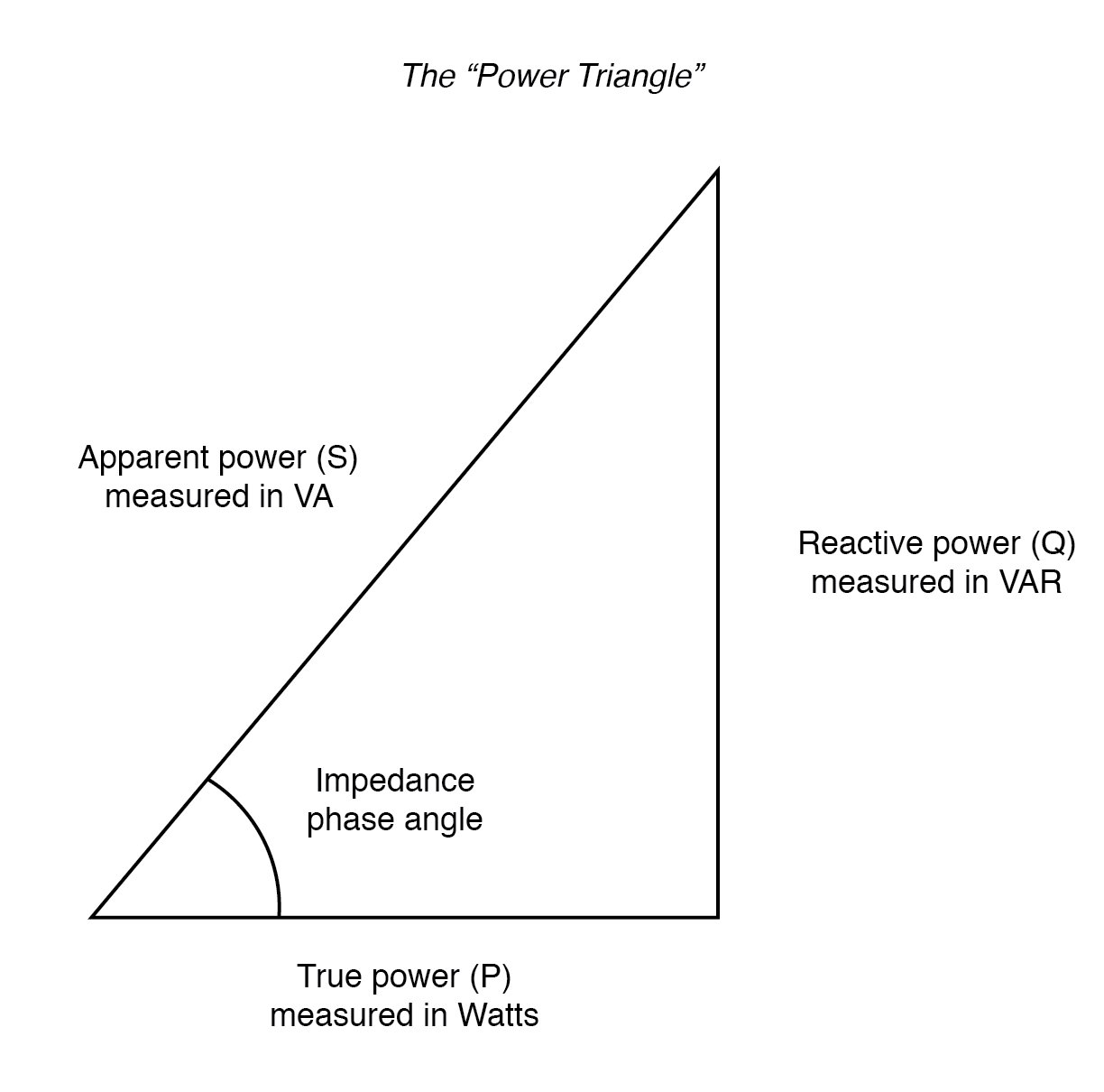
    @ John.G: Before commenting on the above post have a look at the image below.
    The apparent power is always the hypotenuse in the right angled triangle. This means that it is always going to be longer than any of the other sides. Therefore the PF always has the be < or = 1

    the-power-triangle.png

    The power factor is the cosine of the impedance angle. As I am sure you know cosine can not be >1


  • Advertisement
  • Registered Users, Registered Users 2 Posts: 3,623 ✭✭✭John.G


    Point taken and I am aware that the PF cannot be greater than 1, I simply carried out a calculation based on the numbers from the name plate of a grundfos pump.
    I think it is reasonable to accept that the power factor of these type of pumps is apparently very high and my basic measurement would seem to bear this out, I would like to know how this is achieved or could it be a combination of the use of the resistances and the capacitor and it just happens to be high as a result?.


  • Registered Users, Registered Users 2 Posts: 5,374 ✭✭✭aido79


    John.G wrote: »
    Point taken and I am aware that the PF cannot be greater than 1, I simply carried out a calculation based on the numbers from the name plate of a grundfos pump.
    I think it is reasonable to accept that the power factor of these type of pumps is apparently very high and my basic measurement would seem to bear this out, I would like to know how this is achieved or could it be a combination of the use of the resistances and the capacitor and it just happens to be high as a result?.

    Motors are inductive by nature due to their make up as they are made from coils of wire. In a purely inductive circuit in theory the phase angle would be zero. This doesn't exist as there will always be a resistance in the circuit. Adding a capacitor reduces the amount of reactive power in the circuit( see above triangle). This brings the apparent power closer to the real power and makes the impedance angle smaller. (Cosine of 90 degrees = 0 and Cos of 0 degrees = 1)
    Adding resistance to the circuit won't really help with power factor correction.


  • Registered Users, Registered Users 2 Posts: 3,623 ✭✭✭John.G


    Does this imply so that the capacitor, in my (salmson) case of 2.5uf is/can be utilised to improve the PF?, the three outputs are 30W, 46W & 65W @ 230V, it also gives the amps drawn at 65W as 0.28A which again gives a (impossible) PF > 1.0.


  • Moderators, Home & Garden Moderators, Technology & Internet Moderators, Regional East Moderators Posts: 12,641 Mod ✭✭✭✭2011


    aido79 wrote: »
    In a purely inductive circuit in theory the phase angle would be zero.

    Nope, a purely resistive circuit would have a phase angle of zero, (unity power factor).
    A purely inductive circuit would have a phase angle of 90 degrees lagging.
    A purely capacitive circuit would have a phase angle of 90 degrees leading.
    Adding resistance to the circuit won't really help with power factor correction.

    +1

    Capacitors are generally used to improve power factor.


  • Registered Users, Registered Users 2 Posts: 5,374 ✭✭✭aido79


    John.G wrote: »
    Does this imply so that the capacitor, in my (salmson) case of 2.5uf is/can be utilised to improve the PF?, the three outputs are 30W, 46W & 65W @ 230V, it also gives the amps drawn at 65W as 0.28A which again gives a (impossible) PF > 1.0.

    I think you're getting the calculations mixed up. The real power is in watts which is 65w. The apparent power is in voltamps(VA). The apparent power for 0.28A @240V is 240x 0.28 = 67.2.
    Power factor = real power ÷ apparent power = 65÷67.2 which gives a power factor of 0.967.

    Just because that capacitor improves the power factor for that motor doesn't mean it will be suitable for improving the power factor on other motors.


  • Advertisement
  • Registered Users, Registered Users 2 Posts: 5,374 ✭✭✭aido79


    2011 wrote: »
    Nope, a purely resistive circuit would have a phase angle of zero, (unity power factor).
    A purely inductive circuit would have a phase angle of 90 degrees lagging.
    A purely capacitive circuit would have a phase angle of 90 degrees leading.


    +1

    Capacitors are generally used to improve power factor.

    Sorry my mistake. Thanks for the correction. I had a bit of a brain fartðŸ˜


  • Registered Users, Registered Users 2 Posts: 3,623 ✭✭✭John.G


    aido79 wrote: »
    I think you're getting the calculations mixed up. The real power is in watts which 65w. The apparent power is in voltamps(VA). The apparent power for 0.28A @240V is 240x 0.28 = 67.2.
    Power factor = real power ÷ apparent power = 65÷67.2 which gives a power factor of 0.967.

    Just because that capacitor improves the power factor for that motor doesn't mean it will be suitable for improving the power factor on other motors.

    240*0.28 is 67.2 but 230*0.28 is 64.4W. PF=65/64.4 = 1.0093. anyway of no consequence really in trying to see why the high PFs.

    Could you calculate the Capacitor uf required to increase the PF from conditions of say a 230V 65W motor drawing 0.56A (PF of 0.505) to a PF of say 0.85?. (Cosine 59.67 deg)


  • Registered Users, Registered Users 2 Posts: 5,374 ✭✭✭aido79


    John.G wrote: »
    240*0.28 is 67.2 but 230*0.28 is 64.4W. PF=65/64.4 = 1.0093. anyway of no consequence really in trying to see why the high PFs.

    Could you calculate the Capacitor uf required to increase the PF from conditions of say a 230V 65W motor drawing 0.56A (PF of 0.505) to a PF of say 0.85?. (Cosine 59.67 deg)

    At 230v the true power will change as so won't still be 65w so this will have an effect on your calculations

    Use this calculator:

    https://www.rapidtables.com/calc/electric/power-factor-calculator.html

    It shows the maths to work it out too if you're interested. Just be aware the value for real power is in kw so you will put in 0.065 for your motor.


  • Registered Users, Registered Users 2 Posts: 3,623 ✭✭✭John.G


    Thanks, I sort of worked backwards and said that 0.95 is realistically the required PF
    but I only have a 2.5 uf capacitor to achieve this which means that the PF would have been 0.72 if no capacitor, does 0.72 sound like a uncorrected PF for a 65W motor?.


  • Registered Users, Registered Users 2 Posts: 5,374 ✭✭✭aido79


    John.G wrote: »
    Thanks, I sort of worked backwards and said that 0.95 is realistically the required PF
    but I only have a 2.5 uf capacitor to achieve this which means that the PF would have been 0.72 if no capacitor, does 0.72 sound like a uncorrected PF for a 65W motor?.

    Have you any idea of the power factor is when there is a load on it? A lower factor is to be expected if running the motor without a load.

    Different types of motors have different uncorrected power factors so it's hard to tell without knowing more about the motor.


  • Registered Users, Registered Users 2 Posts: 3,623 ✭✭✭John.G


    No, but when running dry (on the table) the power is 52W and 0.225A and a indicated PF of 0.97. (it was drawing 65W when pumping originally)


  • Registered Users, Registered Users 2 Posts: 5,374 ✭✭✭aido79


    John.G wrote: »
    No, but when running dry (on the table) the power is 52W and 0.225A and a indicated PF of 0.97. (it was drawing 65W when pumping originally)

    To be honest I probably wouldn't read too much into what the power factor is unloaded. It will improve when a load is put on it.


  • Registered Users, Registered Users 2 Posts: 3,623 ✭✭✭John.G


    Right, thanks for your help, all very interesting so far.


  • Registered Users, Registered Users 2 Posts: 1,974 ✭✭✭whizbang


    Capacitor for correcting power factor is all well and good, but that capacitor is consuming real power too..

    The Wilo pump is most likely a dc pump internally, with a switchmode powersupply. Notorious for poor PF.


  • Moderators, Home & Garden Moderators, Technology & Internet Moderators, Regional East Moderators Posts: 12,641 Mod ✭✭✭✭2011


    whizbang wrote: »
    Capacitor for correcting power factor is all well and good, but that capacitor is consuming real power too..

    Practically none.


  • Advertisement
  • Moderators, Home & Garden Moderators, Technology & Internet Moderators, Regional East Moderators Posts: 12,641 Mod ✭✭✭✭2011


    John.G wrote: »
    No, but when running dry (on the table) the power is 52W and 0.225A and a indicated PF of 0.97. (it was drawing 65W when pumping originally)

    The phenomena of the power factor deteriorating when no water runs through the pump is used by some devices for dry run protection. Sundyne make devices such as this.

    What instrument are you using to measure the power? The reason that I ask is that many measure the current only and assume unity power factor. For an accurate reading a true wattmeter should be used.


  • Registered Users, Registered Users 2 Posts: 3,623 ✭✭✭John.G


    I'm using a Maplin/Lidl unit which I am quite happy is a true wattmeter.

    Motor Dry Running.
    Speed 1 Rated 30W measured:17.6W measured PF: 0.78 Motor Load: 59%
    Speed 2 Rated 46W measured:31.1W measured PF:0.87 Motor Load: 67.6%
    Speed 3 Rated 65W measured:50.1W measured PF:0.99 Motor Load: 77%

    It would appear that the PF does approach 1 with increasing load even though the capacitor doesn't seem to play any part of any correction, see below.


    I also found another very old salmson only working on one speed, I cut one lead on the capacitor and just gave it a jab to start the motor, the PF of 0.7 stayed the same with/without the capacitor while running.

    Also measured the PF on my oil fired boiler burner fan/oi pump motor and got 102W PF: 0.7 Motor Load 64%


  • Moderators, Home & Garden Moderators, Technology & Internet Moderators, Regional East Moderators Posts: 12,641 Mod ✭✭✭✭2011


    John.G wrote: »
    I'm using a Maplin/Lidl unit which I am quite happy is a true wattmeter.

    You may be correct, but my question is what do you believe this to be the case?
    It would appear that the PF does approach 1 with increasing load
    even though the capacitor doesn't seem to play any part of any correction, see below.

    It will have an impact on PF even if you can’t measure it.


  • Registered Users, Registered Users 2 Posts: 3,623 ✭✭✭John.G


    I would agree that the capacitor should make a substantial difference, my calc in post #15 would (theoretically) indicate a improvement from 0.72 to 0.95 based on the calculations link in post #14, however this is not borne out by me cutting the capacitor in another test, is it possible that the capacitor is no longer in circuit once the motor starts?, I know on larger single phase motors a centrifugal switch takes it out of the circuit, could this be achieved "electrically" in the the above case?.

    What is your opinion on all the above, bearing in mind that the whole thread was started because I just noticed that the full load current on these circ pump motors indicates that very high PFs are achieved and my subsequent tests would appear to support this?.


  • Registered Users, Registered Users 2 Posts: 3,623 ✭✭✭John.G


    Carried out my last test, on speed 1 & 17.5W if I connect a external 3.15 uf across the L&N the PF changes from 0.78 to 0.94.


  • Registered Users, Registered Users 2 Posts: 1,974 ✭✭✭whizbang


    Go on, test just the capacitor... You know you want to..


  • Registered Users, Registered Users 2 Posts: 3,623 ✭✭✭John.G


    I'm happy enough now but forgot to say that after I did the test below, if I leave the internal capacitor disconnected and start the motor externally with that 3.15 uf capacitor then the PF is 0.9 and when removed the PF falls to 0.7 which to me means that the internal capacitor is disconnected somehow (electronically?) after motor runs up so it begs the question how do these motors still reach very high PFs IF the capacitor disconnects, are they true induction motors at all ?..

    "I also found another very old salmson only working on one speed, I cut one lead on the capacitor and just gave it a jab to start the motor, the PF of 0.7 stayed the same with/without the capacitor while running."


  • Registered Users, Registered Users 2 Posts: 5,374 ✭✭✭aido79


    John.G wrote: »
    I'm happy enough now but forgot to say that after I did the test below, if I leave the internal capacitor disconnected and start the motor externally with that 3.15 uf capacitor then the PF is 0.9 and when removed the PF falls to 0.7 which to me means that the internal capacitor is disconnected somehow (electronically?) after motor runs up so it begs the question how do these motors still reach very high PFs IF the capacitor disconnects, are they true induction motors at all ?..

    "I also found another very old salmson only working on one speed, I cut one lead on the capacitor and just gave it a jab to start the motor, the PF of 0.7 stayed the same with/without the capacitor while running."

    The internal capacitor has nothing to do with power factor. Its purpose is to cause the current in the starting winding to be out of phase with the current in the main winding in the stator(stationary part of motor). The magnetic fields created by these windings and the way they are starting at different times repels the magnet in the rotor(part that spins) causing it to turn. Once the motor is up to speed the capacitor is not needed any more and is disconnected.

    I'm not really sure what you mean by true induction motor.


  • Registered Users, Registered Users 2 Posts: 3,623 ✭✭✭John.G


    Do you think that very small induction motors like these can or do run with the sort of PFs that these apparently are without some form of PF correction?.


  • Advertisement
Advertisement