Advertisement
If you have a new account but are having problems posting or verifying your account, please email us on hello@boards.ie for help. Thanks :)
Hello all! Please ensure that you are posting a new thread or question in the appropriate forum. The Feedback forum is overwhelmed with questions that are having to be moved elsewhere. If you need help to verify your account contact hello@boards.ie

Wiring spot lights

Options
  • 27-09-2018 12:29pm
    #1
    Registered Users Posts: 1,226 ✭✭✭


    This is motor light wiring question so I may be on the wrong forum...but here goes
    Basically I have 4 spot lights mounted on bull bar - they are 8 inch Britax and have angel eyes around rim and main bulb in centre. So all lights have a short tail with 3 wires each - a total of 12 wires (4 black, 4 red & 4 brown)
    So what's the best/handiest way to connect all 12 wires in a block behind the bull bar with 3 wires coming out (1 black, 1 red & 1 brown) and into the engine bay to relay switch etc.
    Is there a waterproof block type connection available for this type of connection ?

    Thanks. M.


Comments

  • Posts: 5,238 ✭✭✭ [Deleted User]


    Handiest is not the correct way.

    Impossible to tell without a schematic and specification.

    If I was to guess I'd say red = +12V.
    New 40A ≥ 80A relay; fused switched circuit on 4mm² ≥ 10mm² thin-wall cable from existing or additional fuseblock.

    Brown = stock side marker light relay output parallel circuit. 1.5mm².
    Might cause CAN Bus issues.

    Black = 4mm² ≥ 10mm² thin-wall cable, chassis ground.

    Glue lined clear heat shrink butt crimp terminals or continuous daisy-chained terminations in polyamide flexible conduit or braided armoured flexible conduit.

    7845-5266827.jpg

    S1105-pair.jpg

    I'd steer clear of janky connector blocks in auto-electrics.


  • Registered Users Posts: 1,226 ✭✭✭monseiur


    Thanks Sir Liamalot, that was very helpful, greatly appreciated.

    M.


  • Registered Users Posts: 1,226 ✭✭✭monseiur


    Handiest is not the correct way.

    Impossible to tell without a schematic and specification.

    If I was to guess I'd say red = +12V.
    New 40A ≥ 80A relay; fused switched circuit on 4mm² ≥ 10mm² thin-wall cable from existing or additional fuseblock.

    Brown = stock side marker light relay output parallel circuit. 1.5mm².
    Might cause CAN Bus issues.

    Black = 4mm² ≥ 10mm² thin-wall cable, chassis ground.

    Glue lined clear heat shrink butt crimp terminals or continuous daisy-chained terminations in polyamide flexible conduit or braided armoured flexible conduit.

    7845-5266827.jpg

    S1105-pair.jpg

    I'd steer clear of janky connector blocks in auto-electrics.

    Hi Sir Liamalot

    Can I be bold enough and ask one final question :
    I was in Halfords this morning looking for a suitable relay switch for the spot lights and the guy there advise me to find out the correct wattage / amps etc. first to ensure that I get the right one, it seems they have 4 different types in stock.
    So I have 4 - 8 inch Britax spot lights - each have a 55 watt H3 Halogen main beam and LED angel eyes type light around the rim
    What watt/amp relay would you recommend
    Thanks M.


  • Moderators, Home & Garden Moderators, Technology & Internet Moderators, Regional East Moderators Posts: 12,558 Mod ✭✭✭✭2011


    First work out the total main beam load:
    4 x 55 = 220 Watts

    Next work out the current the relay will switch for main beam:
    220/12 = 8.33 amps (assuming a 12 volt DC system)

    A relay rated to switch 25A at 12 volts DC will give you a nice safety margin.


  • Posts: 5,238 ✭✭✭ [Deleted User]


    Bosch-style relays are low grade and generally over-rated. Prone to contact atrophy from DC switching.
    For your 20A load with possibly a 60A inrush, I'd recommend at least a 40A Relay.

    0-727-07-durite-12v-75a-heavy-duty-make-and-break-relay-10105-p.jpg


    Clicky

    I've replaced quite a few.
    If you look at wiring kits they usually supply 30A relays with 10A lighting kits. Use 4mm² thin wall cable.


    Terminal Covers for the Relay

    HTB1JhQdceEJL1JjSZFGq6y6OXXaK.jpg

    4 Way ATO Blade FuseBlock

    Car-4-Way-Circuit-Standard-ATO-Blade-Fuse.jpg

    4mm² +12V Feeder (fused at 60A at battery positive or stock fuseblock)
    Fuses
    • 40A Aux Lighting Master -> [Relay 30 terminal] & [Fuse 4 Feeder] 4mm²
    • 15A [Relay 87 terminal] -> Centre Spots 2.5mm²
    • 15A [Relay 87 terminal] -> Outer Spots 2.5mm²
    • 10A Illuminated Dash Switch -> [Relay 85 Terminal] 1.5mm²

    Angel Eyes I'd link to side lighting. If that makes the ECU throw a wobbler then I'd add another relay for these...maybe solid state.


  • Advertisement
  • Posts: 5,238 ✭✭✭ [Deleted User]


    maxresdefault.jpg


  • Moderators, Home & Garden Moderators, Technology & Internet Moderators, Regional East Moderators Posts: 12,558 Mod ✭✭✭✭2011


    For your 20A load with possibly a 60A inrush, I'd recommend at least a 40A

    Not sure where the 20 amps comes from.
    The largest current (for main beam) to be switches is 8.33 amps. Surely a relay rated for 25 amps as suggested is sufficient for this?


  • Registered Users Posts: 1,226 ✭✭✭monseiur


    Thanks 2011 and Liamalot...... greatly appreciated. I must admit to feeling more than a little amateurish after reading your post !
    M.


  • Moderators, Home & Garden Moderators, Technology & Internet Moderators, Regional East Moderators Posts: 12,558 Mod ✭✭✭✭2011


    monseiur wrote: »
    Thanks 2011 and Liamalot...... greatly appreciated. I must admit to feeling more than a little amateurish after reading your post !
    M.


    Not a problem. Very informative posts from Liamalot (as usual), I think the relays is suggesting are a bit OTT as he was basing the selection on a far higher design current that the actual (20 instead of 8.33 amps). Having said that the larger relays will work perfectly, they may just cost a bit more.


    A note of caution: As the applied voltage (12VDC) is low the current must be higher to produce a given output (in terms of watts) compared to mains voltage (230VAC). Higher currents mean that the risk of a bad connection overheating and causing a fire are dramatically increased. So you need to ensure that all connections are very good (good tight crimps).
    Heat generated at a connection = the current squared x the resistance across the connection

    So in this case a connection of just 1 ohm resistance will generate 70 watts of heat concentrated on one tiny point.


    To explain in layman's terms the following extracts from Liamalot's excellent and detailed post above:

    1) Read "Prone to contact atrophy from DC switching" as "may burn out due to wear and tear from switching".

    2) Read " If that makes the ECU throw a wobbler then I'd add another relay for these...maybe solid state" this may require it's own relay.

    My personal preference would be for a standard electro mechanical relay (like the other one) as I find that many solid state relays can run quite hot and are less reliable.


  • Posts: 5,238 ✭✭✭ [Deleted User]


    220watts ÷ 11volt = 20Amp.

    OTT...:rolleyes:
    60Amp inrush!


    Solid state relays require heatsinks or derating.


  • Advertisement
  • Moderators, Home & Garden Moderators, Technology & Internet Moderators, Regional East Moderators Posts: 12,558 Mod ✭✭✭✭2011


    220watts ÷ 11volt = 20Amp.

    I deleted a “1” by mistake, my bad :(
    Obviously my equation should have been 220/12 = 18.33 amps.

    Not sure why you are assuming 11 volts and not 12??

    Solid state relays require heatsinks or derating.

    = more hassle than they are worth.


  • Posts: 5,238 ✭✭✭ [Deleted User]


    I assume the worst. A flat 12v battery is 10.5v.

    Solid state relays are worth the hassle for low on consumption maintained loads, like extending switched signal from CANBus load sensing circuits.

    The truth about relays. Clicky.


  • Moderators, Home & Garden Moderators, Technology & Internet Moderators, Regional East Moderators Posts: 12,558 Mod ✭✭✭✭2011


    I assume the worst. A flat 12v battery is 10.5v.

    The spots are rated at 55W, but only when 12VDC is applied to them. Using ohms law we know that the resistance of each lamp is about 2.62 ohms.
    P/V = I
    55/12 = 4.48 amps
    V/I = R
    12/4.48 = 2.67 ohms

    Therefore if you apply 10.5 volts to them they will only draw 3.93 amps each.
    V/R= 10.5/2.67 = 3.93 amps

    This means a total current of only 15.73 amps.

    In other words a lower voltage applied to a fixed resistance will draw a lower current.


    The power consumption is only 41.27 watts which is why the lights are not as bright at a lower voltage.
    V x I = P
    10.5 x 3.93 = 41.27 W


    Solid state relays are worth the hassle for low on consumption maintained loads, like extending switched signal from CANBus load sensing circuits.

    I think it would be ok to be honest. The current drawn by the coil of the relay is minimal.
    Failing that you could wire them in the same way as the 60 amp relay


  • Posts: 5,238 ✭✭✭ [Deleted User]


    I appreciate linear loading. 20a circuit needs a 60a relay...I don't see the point worrying about the minor.

    I could argue the filaments are rated to alternator voltage of 14v but I don't.

    CANBus has nothing to do with the 20a new circuit on a new fuseblock with a "40A >75A" relay. Because I didn't advise attaching it to any stock circuits like I did the side marker lights.


  • Moderators, Home & Garden Moderators, Technology & Internet Moderators, Regional East Moderators Posts: 12,558 Mod ✭✭✭✭2011


    I appreciate linear loading. 20a circuit needs a 60a relay...I don't see the point worrying about the minor.

    I don’t follow. Your point appeared to be that a lower voltage would draw a higher current when you devided 220 watts by 10.5 volts and got 20 amps.
    CANBus has nothing to do with the 20a new circuit on a new fuseblock with a "40A >75A" relay.

    If you choose to wire it that way....
    Because I didn't advise attaching it to any stock circuits like I did the side marker lights.[/QUOTE]

    Makes sense.

    I think we are splitting hairs. To summarize everything you said will work and will provide a robust solution.


  • Posts: 5,238 ✭✭✭ [Deleted User]


    2011 wrote: »
    I don’t follow. Your point appeared to be that a lower voltage would draw a higher current when you devided 220 watts by 10.5 volts and got 20 amps.

    Apologies for the confusion 2011.

    I say 220/11V = 20A
    like I say 3.5kW/220V = 15.9A
    like gravity = 10N

    It's a modest and favourable margin for error.

    I believe you come from an industrial background, where big ticket switchgear is the norm. Industry standard is for full rated load, @ 100% duty, continuous..no bother! ABB, Schneider, MK, Albright.
    Independant laboratory tested and certified.

    Autoelectrics is the wild west. Underwiring is the norm, extra low voltage is open season to chocy blocks. Current limiting is achieved by lack of capability.
    Most automotive relays are branded with their instantaneous rating and derate quickly under voltage drop, contact pitting and corrosion and heat saturation. So when I want a 10A auto relay I buy a 30A instantaneous relay.

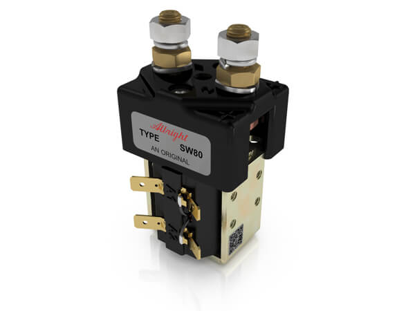
    I collect and repurpose 100A Contactors from Albright, I have one I load to 110A peak continuous, it weighs three times the Durite "equivalent"

    SW80.jpg

    M8 High Current Studs


    Relay-Heavy-Duty-Make-Break-100A-24V.jpg

    M6 high current studs.


    Current limiting over-rated split charge relays are one of the most common constriction points on the generic camper dual battery charging circuit's pulling power.

    In lay mans terms if you want a fit for purpose auto relay; overspec by a factor of three.
    10A circuit, "30A" Relay
    It's not OTT it's counter-marketing.
    (Compare the price to something equivalent DIN rail and tell me it's just as good!)

    I've more melted cigarette lighter plugs and relays than you'd believe.
    12V I think sometimes is regulated by the users' lack of imagination.
    Cigarette lighter plugs derate by a factor of 3.
    10A Cig lighter plug = 3A


  • Moderators, Home & Garden Moderators, Technology & Internet Moderators Posts: 10,952 Mod ✭✭✭✭Stoner


    I believe you come from an industrial background, where big ticket switchgear is the norm.

    Inaccurate Sir Liamalot, as much as it would be for me to offer that I believe you come from a solar panel. background, neither comment would be fair or accurate and could both be taken as attempting to undermine the level of knowledge and advice offered by the other poster.

    All that said there's some great advice here for the op, it's a good read and it's always good to keep the thread on topic and to be mindful of our DIY origins.


  • Posts: 5,238 ✭✭✭ [Deleted User]


    Some vehicles have solar panels.

    I was attempting to undermine the proclaimed suitability of standard bosch type automotive relays.
    Something I have much experience concerning

    See the link in post #13.

    Look it's a 10A lighting kit >Clicky< with a spec-ed
    30A Relay included from Ring

    Here is another clicky.


Advertisement