Advertisement
If you have a new account but are having problems posting or verifying your account, please email us on hello@boards.ie for help. Thanks :)
Hello all! Please ensure that you are posting a new thread or question in the appropriate forum. The Feedback forum is overwhelmed with questions that are having to be moved elsewhere. If you need help to verify your account contact hello@boards.ie
Hi there,
There is an issue with role permissions that is being worked on at the moment.
If you are having trouble with access or permissions on regional forums please post here to get access: https://www.boards.ie/discussion/2058365403/you-do-not-have-permission-for-that#latest

Commodore SID arduino shield PCBs for anyone who wants one

  • 04-01-2017 7:06pm
    #1
    Registered Users, Registered Users 2 Posts: 437 ✭✭


    I recently put together one of these https://github.com/atbrask/RealSIDShield
    It's basically a shield for the Arduino Uno that allows you to control a Commodore SID chip (6581 or 8580).
    It's a pretty cool project if you've an old SID chip lying around.
    You load a sketch onto the Arduino that makes it emulate a MOS 6510 (C64 CPU) and then stream SID files through USB using a python script.

    Anyway, I got 10 of the PCBs made and only used 1 (I ended up getting one 8580 while collecting 8 6581s for a midibox project.)

    So if anyone would like one just lot me know and just give us the €2 or whatever for posting.

    I've also lots of the resistors and caps and inductors left over and 2 or 3 audio jacks and 1 buck converter so the first few people can get these too.

    Note that nearly all the components are SMT so make sure you can solder these. Also some of the components are different depending on whether you use a 8580 or 6581.

    Everything's at the github link. The net file has the components needed and their footprints.

    You'll also need to use the older version of python (2.7 or whatever) for the script to run.

    Here's a crappy little video of me playing "Monty on the run" through mine.
    I made a little java program to load the python script because I got fed up of typing tune names and locations into the command prompt

    https://youtu.be/Vo5ahVfdsu8


Comments

  • Registered Users, Registered Users 2 Posts: 3,726 ✭✭✭The Last Bandit


    Yep I'm interested in messing with one, send me a PM with your paypal and I'll throw you a few quid for it :)


  • Registered Users, Registered Users 2 Posts: 4,335 ✭✭✭KeRbDoG


    I'd also be interested - PM me also :)


  • Moderators, Computer Games Moderators Posts: 3,186 Mod ✭✭✭✭Dr Bob


    Hi , that sounds great , send me on a PM if you can .
    cheers


  • Moderators, Category Moderators, Computer Games Moderators, Society & Culture Moderators Posts: 34,679 CMod ✭✭✭✭CiDeRmAn


    I have no idea what to do with one so I don't want one, but fair play to you for passing them on to the unwashed bunch hereabouts!


  • Registered Users, Registered Users 2 Posts: 9,175 ✭✭✭Doge


    Hey Wobzilla!
    This is Smithy from the MIDIbox forums.

    Was it a MB-6582 you built with the Pactec PT-10 enclosure and a front panel from Schaeffer?

    Managed to pretty much finish mine, just have 3 feedback pots left to put in now.

    You can count me in for a board also! It would be a quick and easy way of testing SIDs!


  • Advertisement
  • Registered Users, Registered Users 2 Posts: 3,726 ✭✭✭The Last Bandit


    Got the board, thanks very much :) Now, just need to root around in the attic to find a suitable SID :)


  • Registered Users, Registered Users 2 Posts: 437 ✭✭wobzilla1


    It actually took me a while to figure out running the python script once I built it.
    You need to install the old version of python (2.7).
    Then you need to add python's location to your path environmental variable.
    You then have to get py65 and pyserial from pypi and install them.
    Then you can go to the location of the Realised.py file in command prompt and run
    python RealSID.py COM4 track.sid
    Replace COM4 with whatever com port your arduino is on (check device manager) and track.sid is the sid file you want to play.
    You'll have to type the full location.
    You can also put a -s 1 or -s 2 or whatever after the RealSID.py to select a track if the sid has more than 1.

    I'll upload the java program I made somewhere as you can just click the file you want rather than type the full name.
    If you download the hvsc sid collection, the file names are pretty long and the directory structure is a bit of a cluster****


  • Registered Users, Registered Users 2 Posts: 437 ✭✭wobzilla1


    Alright, the java jar file is here


    The source files are here if anyone wants to dick round with them. It could probably be made a whole lot better, I only ever did java as a hobby and haven't used it in years.

    There's a few prerequisites to using the java program besides the obvious having java installed.
    1: You need to put the RealSID.py file in C:\sid\
    2: You need to put a sid file that starts with silence into C:\sid\ and name it reset.sid

    The reason for 2 is that when the python script is killed, the Arduino keeps sending the last instructions to the SID chip and so the SID keeps outputting the same note until you load a new tune.
    I got around this by loading a file with silence (or a sid file that doesn't work) and then killing the script after 1 second. This should ensure when you press the stop button, the SID stops making sound.

    I used the ghouls n ghosts sid file from the HVSC collection


  • Registered Users, Registered Users 2 Posts: 9,175 ✭✭✭Doge


    Hey wobzilla, just to let you know that the your package came safe and sound today.

    Now I feel like ive robbed you with all the stuff thrown in there!

    Thanks a million for being so generous to the forum, this will serve me nicely as an authentic sid player and also to practice my SMD soldering skills.


  • Registered Users, Registered Users 2 Posts: 437 ✭✭wobzilla1


    No problem, I wouldn't have used the components anyway.
    I rarely need smt components for a project.
    Just be aware that the electrolytic caps are a bit big for the footprint on the board. I had to pull off the plastic Base to be able to solder it.
    Just ordered the board set for the MB-6582 there as well.
    Time to start hunting for components now


  • Advertisement
  • Registered Users, Registered Users 2 Posts: 9,175 ✭✭✭Doge


    wobzilla1 wrote: »
    No problem, I wouldn't have used the components anyway.
    I rarely need smt components for a project.
    Just be aware that the electrolytic caps are a bit big for the footprint on the board. I had to pull off the plastic Base to be able to solder it.
    Just ordered the board set for the MB-6582 there as well.
    Time to start hunting for components now

    Awesome stuff.

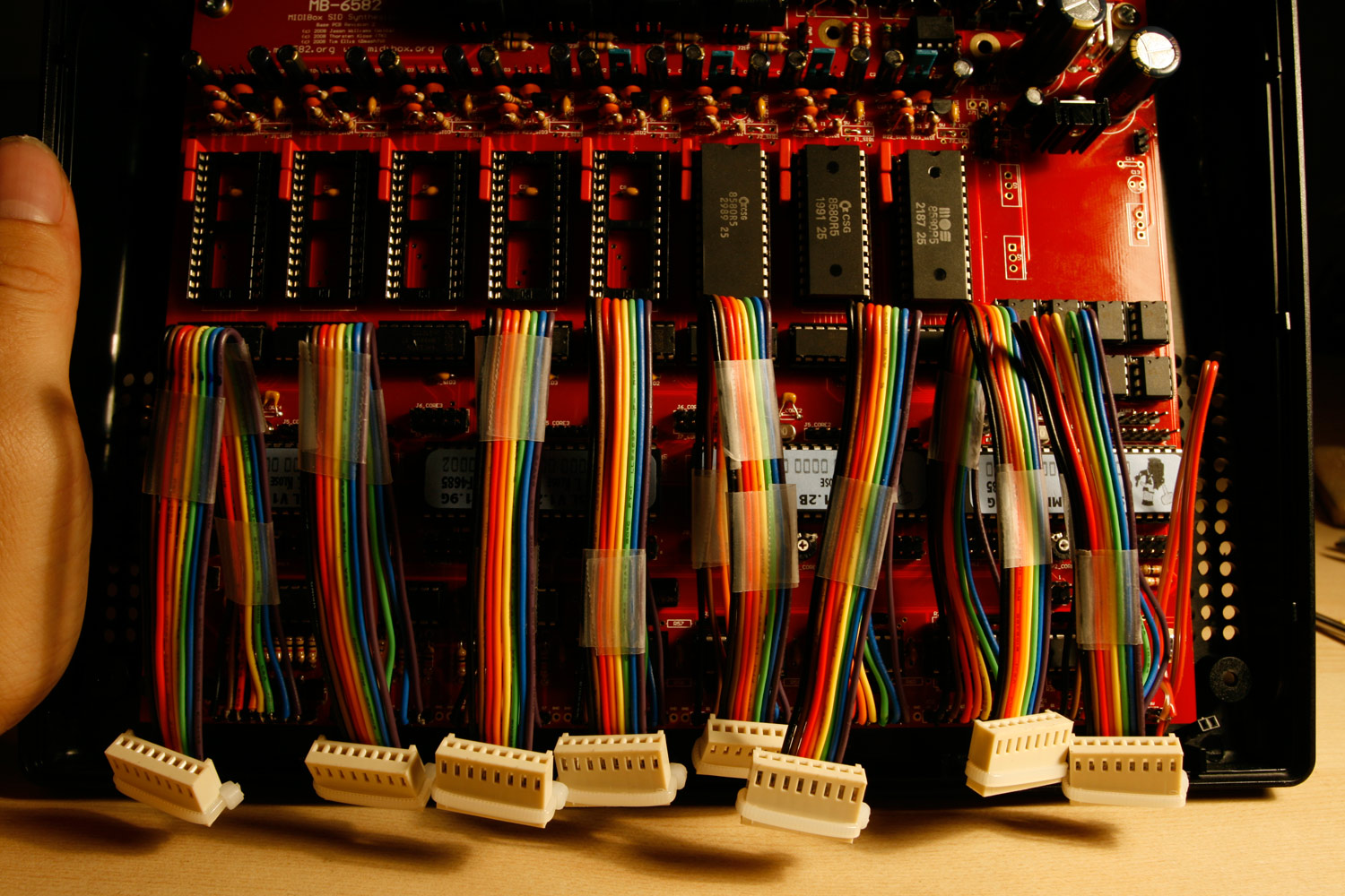
    For the interconnecting wires between both mb-6582 PCBs I would advise using these flexible kind of wires Hawkeye and I used, as opposed to the stiff ribbon cable Wilba mentions in his guide:

    http://midibox.org/forums/topic/14564-building-the-mb-6582-control-surface-photo-tutorial/?do=findComment&comment=129752

    post-7895-089852200%201282899260.jpg

    I had problems with the Control surface and found myself opening the case a lot and the stiff ribbon cables broke on me.

    It looks a bit messier but it will resist strain much better.

    Also if I had my time back I wouldn't bother with the JB Weld solution for mounting the PCB standaoffs to the Front Panel.

    I had the standoffs come loose from the weld after opening up the case so many times.

    Even though it may not look as pretty, i would make use visible screws that go through the front panel ,(like the 4 in the corners) with a nut at the other end of the screw to hold the PCB in place, you could always use black screws to make it look neater.

    I'm pretty sure a user did this instead of using JB Weld so there may even be an .FPD file for this option on the forum somewhere.


  • Registered Users, Registered Users 2 Posts: 9,175 ✭✭✭Doge


    Here's one user that just used the 4 corner holes and no hex stand offs to mount the board to the front panel and case:

    http://midibox.org/forums/topic/14564-building-the-mb-6582-control-surface-photo-tutorial/?do=findComment&comment=173994


  • Registered Users, Registered Users 2 Posts: 9,175 ✭✭✭Doge


    Hey guys,

    Im after making a component list on Google Sheets for the SID Shield, with links to Farnell for most of the parts.

    https://docs.google.com/spreadsheets/d/1CIJ_7EiK3G0lqSWOhu66NV5Nq_EtbsGzNIktknhh1fw/edit?usp=sharing

    It was pretty time consuming trying to make sure the values and footprints of each part were okay! Good practice for me though. And put my digital calipers to good use!

    If anyone wants to scrutinize it feel free!

    Might do a proper BOM then when its confirmed okay.


  • Registered Users, Registered Users 2 Posts: 4,335 ✭✭✭KeRbDoG


    Doge wrote: »
    Hey guys,

    Im after making a component list on Google Sheets for the SID Shield, with links to Farnell for most of the parts.

    https://docs.google.com/spreadsheets/d/1CIJ_7EiK3G0lqSWOhu66NV5Nq_EtbsGzNIktknhh1fw/edit?usp=sharing

    It was pretty time consuming trying to make sure the values and footprints of each part were okay! Good practice for me though. And put my digital calipers to good use!

    If anyone wants to scrutinize it feel free!

    Might do a proper BOM then when its confirmed okay.

    I went through that painful process two weeks ago :) now to find a clear space and time to get it all together


  • Registered Users, Registered Users 2 Posts: 9,175 ✭✭✭Doge


    EDIT: Resolved this issue, see my next post.
    wobzilla1 wrote: »
    Alright, the java jar file is here


    The source files are here if anyone wants to dick round with them. It could probably be made a whole lot better, I only ever did java as a hobby and haven't used it in years.

    There's a few prerequisites to using the java program besides the obvious having java installed.
    1: You need to put the RealSID.py file in C:\sid\
    2: You need to put a sid file that starts with silence into C:\sid\ and name it reset.sid

    The reason for 2 is that when the python script is killed, the Arduino keeps sending the last instructions to the SID chip and so the SID keeps outputting the same note until you load a new tune.
    I got around this by loading a file with silence (or a sid file that doesn't work) and then killing the script after 1 second. This should ensure when you press the stop button, the SID stops making sound.

    I used the ghouls n ghosts sid file from the HVSC collection


    Right guys, everything is soldered and SID voltages tested fine.
    Python 2.7 is installed.


    However I'm trouble trying to install py65.
    When i run "python setup.py install" in the py65 directory in command prompt I get this error:
    Traceback (most recent call last):
      File "setup.py", line 16, in <module>
        from setuptools import setup, find_packages
    ImportError: No module named setuptools
    

    So I downloaded setuptools, and tried to install that it returned this error:
    ImportError: No module named packaging.version
    

    So i install packaging, then setuptools needs pyparsing. I install that.

    Then when i try to install setuptools again i get this error:
    File "C:\Python27\lib\site-packages\packaging\requirements.py", line 59, in <module>
        MARKER_EXPR = originalTextFor(MARKER_EXPR())("marker")
    TypeError: __call__() takes exactly 2 arguments (1 given)


    Absolutely lost now as it doesnt ask for another module to install! :pac:

    Anyone manage to install it okay?


  • Registered Users, Registered Users 2 Posts: 9,175 ✭✭✭Doge


    Fixed the issue above by installing the x86 version of python 2.7 instead of the 64-bit version,
    and then downloading the setuptools installer specifcally for version 2.7.

    It appears setuptools is not backwards compatible so you need to download the correct version for your version of pyhton.


    Anyway managed to get it to play but with a very loud noise as you can hear in the first part of the video.

    The noise seemed to have settled down afterwards and went more high pitched.


    One possible issue is that the middle 2 pins on one side of U3 the DC to DC converter chip were connected.

    Not sure if this is meant to be or if theres a short underneath somewhere.

    If anyone wants to check those for continuity I'd be delighted!


  • Registered Users, Registered Users 2 Posts: 9,175 ✭✭✭Doge


    Just got the fright of my life after playing back your video wobzilla and this one came on next! :eek:


    What sort of creature is that little dude? :D

    Thought it was something out of Aliens when I saw it first! :pac:


  • Registered Users, Registered Users 2 Posts: 437 ✭✭wobzilla1


    I'll check the boost converter on mine when I get home today.
    I only had to install py65 and pyserial myself and they both worked off the bat. I've a 64 bit version of Windows and I just used the default installer.

    That lad's an axolotl, I forgot how much of a fat shît he was when I had him in the small tank.
    They're a type of amphibian that doesn't develop lungs and stays aquatic as adults.
    Apparently they're just about extinct in the wild now but loads of the albino ones in captivity.
    They're pretty cool, they can regrow limbs and even parts of their head apparently


  • Registered Users, Registered Users 2 Posts: 437 ✭✭wobzilla1


    Pins 6 and 7 show continuity, there's actually a resistor between them but it's only 1 ohm.

    Not sure what could be causing the noise, mine just hisses softly when it's not playing something.
    Do you have another sid to try?

    Where did you get your front panel made for the MB-6582 btw?


  • Registered Users, Registered Users 2 Posts: 9,175 ✭✭✭Doge


    wobzilla1 wrote: »
    Pins 6 and 7 show continuity, there's actually a resistor between them but it's only 1 ohm.

    Not sure what could be causing the noise, mine just hisses softly when it's not playing something.
    Do you have another sid to try?

    Where did you get your front panel made for the MB-6582 btw?

    Thanks a lot for testing that for me dude!

    Sonething weird happened with your post today, couldnt view it for ages, and im only seeing it now. My usercp kept highlighting the thread for new posts also! Odd.

    Not so sure what I did wrong, I did use a different value cap as mentioned in the readme. Might exchange that for the value you sent me. Not too concerned anyway since it works and it shows i can solder smd.

    I used Schaeffer for the front panel.

    https://www.schaeffer-ag.de/en/

    The front panel they sent me didnt have the paint infilled properly, it was a but blotchy in places. Nothing major but a minor inconvenience.

    So after showing them photoe they decided to send another one out for free by express ups, which I gave to a member on the forum.

    So they're very professional and I'd highly recommend them.


  • Advertisement
  • Registered Users, Registered Users 2 Posts: 4,335 ✭✭✭KeRbDoG


    Just got around to building this now - right at the end to discover I've the wrong footprint 330uH inductor :) one ordered up.
    I've learned that I'm not amazing at SMD soldering, I've checked connectivity of all pins/legs but it just doesn't look pretty.
    Doge wrote: »
    One possible issue is that the middle 2 pins on one side of U3 the DC to DC converter chip were connected. Not sure if this is meant to be or if theres a short underneath somewhere. If anyone wants to check those for continuity I'd be delighted!

    I believe pins 2 & 4 are connected on the PCB underneath the IC, and pins 6 & 7 from the 1ohm resistor as mentioned.
    Pic of the board here from the github site.


  • Registered Users, Registered Users 2 Posts: 4,335 ✭✭✭KeRbDoG


    OK, inductor installed so I (without the SID installed) started to buzz out some of the input pins and somehow I have the 5V line of the Uno connecting to GND on the SID shield - no idea how/where

    Any suggestions Doge/wobzilla1?


  • Registered Users, Registered Users 2 Posts: 3,726 ✭✭✭The Last Bandit


  • Registered Users, Registered Users 2 Posts: 4,335 ✭✭✭KeRbDoG


    KeRbDoG wrote: »
    OK, inductor installed so I (without the SID installed) started to buzz out some of the input pins and somehow I have the 5V line of the Uno connecting to GND on the SID shield - no idea how/where

    Any suggestions Doge/wobzilla1?

    Was this the correct inductor to use?


  • Registered Users, Registered Users 2 Posts: 9,175 ✭✭✭Doge


    KeRbDoG wrote: »
    Was this the correct inductor to use?

    It matches the spec and brand of the one I bought,
    330uH, 0.6A.

    Im not sure whats causing the connection between 5V and GND.
    Have you all components soldered?

    Is there any tests you would like us to do?

    I just measured the voltages to the SIDs IC socket using the pinout on Wikipedia.


Advertisement