Advertisement
If you have a new account but are having problems posting or verifying your account, please email us on hello@boards.ie for help. Thanks :)
Hello all! Please ensure that you are posting a new thread or question in the appropriate forum. The Feedback forum is overwhelmed with questions that are having to be moved elsewhere. If you need help to verify your account contact hello@boards.ie
Hi there,
There is an issue with role permissions that is being worked on at the moment.
If you are having trouble with access or permissions on regional forums please post here to get access: https://www.boards.ie/discussion/2058365403/you-do-not-have-permission-for-that#latest

Immersion Timer and 5 core Cable Question...

  • 12-07-2016 11:02am
    #1
    Registered Users, Registered Users 2 Posts: 132 ✭✭


    Hi there folks,

    Quick one for you all....

    I am installing a digital timer rated at 3KW on my immersion. My Immersion strangely says it is actually rated at 4.85KW so given the power involved will be using a 25amp contactor controlled by the timer rather than switching the immersion directly. The contactor will then supply the original Sink/Bath switch.

    The timer uses Live and Neutral in and then switches both Live and Neutral out from a DP Fused Spur.

    I am using 2.5mm cable from mains through the contactor to the immersion switch as usual, but don't need the same cable for the timer supply as it needs well below 1A for its own power plus the power out to the contactor coil.

    In an attempt to keep the cabling to a minimum and keep it it as neat as possible my plan is therefore:

    I have a 3 module enclosure to mount the Contactor.

    With 5 core 1.0mm cable - using 3 of the cores (Br, Bl and YG for L,N & E) to supply the timer with the L via a 6A MCB also mounted in the enclosure to protect the 1mm cable. The Earth is only required because I will be using a metal back box to mount the timer outside the hot press so I need to ground that.

    The remaining 2 cores (Black and Grey) will supply the switched L & N back to the contactor coil. Replacing the 13A fuse in the timer with a 3A one probably just for belts and braces....

    My question then is will there be a problem running both timer mains supply in and switched main feed out within the same 5 core cable? Total cable length will be less than 1 metre.

    Any thoughts welcome!

    MM


Comments

  • Moderators, Home & Garden Moderators, Technology & Internet Moderators, Regional East Moderators Posts: 12,641 Mod ✭✭✭✭2011


    Mizuno Man wrote: »
    Hi there folks,

    Quick one for you all....

    I am installing a digital timer rated at 3KW on my immersion. My Immersion strangely says it is actually rated at 4.85KW so given the power involved will be using a 25amp contactor controlled by the timer rather than switching the immersion directly. The contactor will then supply the original Sink/Bath switch.

    That will work but as far as I know digital timera are now available that can switch a load of that size.
    The timer uses Live and Neutral in and then switches both Live and Neutral out from a DP Fused Spur.

    I would suggest that just switching the phase is sufficient.
    I am using 2.5mm cable from mains through the contactor to the immersion switch as usual, but don't need the same cable for the timer supply as it needs well below 1A for its own power plus the power out to the contactor coil.

    Correct.
    My question then is will there be a problem running both timer mains supply in and switched main feed out within the same 5 core cable? Total cable length will be less than 1 metre.

    I can't see a problem with this. It just seems like a lot of hassle for an immersion timer, although I had to do something similar in the past. I suggest that you source a digital timer that can switch the load without requiring a contractor.


  • Registered Users, Registered Users 2 Posts: 132 ✭✭Mizuno Man


    Thanks a mill for the reply 2011.

    Yes I really should look for a higher capacity timer but I couldn't find any digital programmable during my quick search. Only analogue...

    But the main problem really was my assuming I had a 3kw immersion, buying a 3kw digital timer, starting to install it, and only checking the actual immersion rating just before flipping the power back on!

    So I have a 50 quid timer I can no longer return! I figured getting it all working with just another 45 euro put out for the Contactor, MCB, enclosure and a couple of metres of 5 core was the quickest and simplest solution!!

    I know switching just the live will suffice for the Contactor coil, but is there any harm in switching both L & N? Do I protect the set up any further by doing both?


  • Moderators, Home & Garden Moderators, Technology & Internet Moderators, Regional East Moderators Posts: 12,641 Mod ✭✭✭✭2011


    No harm in switching live & neutral.

    Your immersion sounds very nonstandard. Can you measure the current it draws with a gripon ammeter ?


  • Registered Users, Registered Users 2 Posts: 132 ✭✭Mizuno Man


    2011 wrote: »
    No harm in switching live & neutral.

    Your immersion sounds very nonstandard. Can you measure the current it draws with a gripon ammeter ?

    I don't have an ammeter that can handle that load to measure it I'm afraid. Only multimeter to hand.

    Non-standard is the way I would describe most things in my house! It sounds like a big immersion heater for a relatively small tank to be honest. I wouldn't be surprised if 4.85kw is the theoretical rating of both elements running together and it's actually 1.85 & 3 kW which would be closer to a 'standard' set up I guess.

    Using the Contactor will keep me happy that everything is very capable of handling their respective loads while still staying fully protected in the meantime. Better than second guessing the labelled rating perhaps....


  • Registered Users, Registered Users 2 Posts: 132 ✭✭Mizuno Man


    Oh and one more question....

    Does it matter which way around the Contactor is connected? What I mean is - it is apparently intended that the mains feed input would be connected to the top and the switched output from the bottom. Given it is AC we are talking about does it really matter?

    My supply will be coming into the bottom of the enclosure so it will be simpler to connect the feed to the bottom and the output to the top and on out of the top of the enclosure to the immersion switch.

    If Contactors are 'directional' so to speak I'll just mount the Contactor upside down on the DIN rail and it will be all the same anyway I'm sure....


  • Advertisement
  • Moderators, Home & Garden Moderators, Technology & Internet Moderators, Regional East Moderators Posts: 12,641 Mod ✭✭✭✭2011


    A contactor is essentially a switch. Normal practice would be to connect the supply to the top (as you say) but in reality it will make no difference to the operation of the circuit. I would mount it the right way up as this is the way it is designed to be installed.


  • Registered Users, Registered Users 2 Posts: 132 ✭✭Mizuno Man


    Thanks for all the replies 2011.

    Very helpful thank you.....


  • Registered Users, Registered Users 2 Posts: 132 ✭✭Mizuno Man


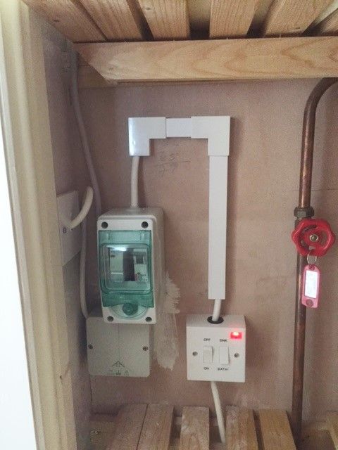
    All done. Really wasn't that much trouble. Main thing is to do as many of the connections and wiring as possible on the bench before you get into the cramped space of the hot press. Read a few specs of contactors after your post 2011 and some do specifcally say they can't be installed inverted.

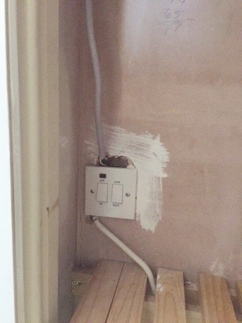
    Previously had an old immersion switch with a dodgy parasite feed to a power shower:

    Before.jpg

    Not the tidiest trunking job but I wanted to leave enough 2.5mm cable between the enclosure and the new immersion switch to be able to comfortably keep it out of harms way while still having enough room to bend it around the corner!

    Hot%20Press.jpg

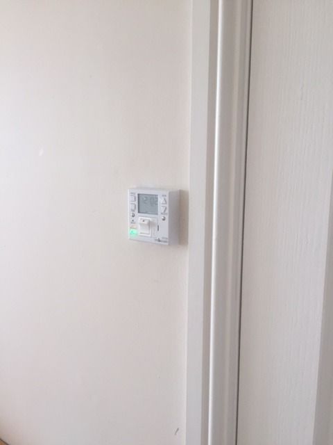
    And finally a decent digital timer controlling the whole lot:

    Timer.jpg

    I misread the timer description in the end. It has a DP fused spur controlled by the main switch on the front, but the timer itself only switches the phase output - which is a bit simpler I guess.

    Thanks again for your help 2011....All works a treat.... :)


Advertisement