Advertisement
If you have a new account but are having problems posting or verifying your account, please email us on hello@boards.ie for help. Thanks :)
Hello all! Please ensure that you are posting a new thread or question in the appropriate forum. The Feedback forum is overwhelmed with questions that are having to be moved elsewhere. If you need help to verify your account contact hello@boards.ie
Hi there,
There is an issue with role permissions that is being worked on at the moment.
If you are having trouble with access or permissions on regional forums please post here to get access: https://www.boards.ie/discussion/2058365403/you-do-not-have-permission-for-that#latest

Connecting a Zig marque 1 panel

  • 14-12-2015 9:30pm
    #1
    Registered Users, Registered Users 2 Posts: 6,908 ✭✭✭


    I've been doing a small bit of work on my (new to me) bongo. It came with a Zig unit which was mounted in the kitchen which wasn't installed.

    I want to mount it in a spare DIN socket in the dash, hopefully it will allow me to switch off the leisure battery circuits and also give me a readout of the leisure battery status. I'm not concerned about connecting the starter battery to it or what the point in doing this would be?

    Any advice as to how it should be wired?
    2015_12_14_19_25_03.jpg
    2015_12_14_19_25_22.jpg
    BTW I've a thread in projects and builds:

    http://www.boards.ie/vbulletin/showthread.php?t=2057533779


Comments

  • Posts: 5,238 ✭✭✭ [Deleted User]


    Starter +ive to lower blade of source selection rocker switch LHS (panel front).
    Leisure battery +ive to upper blade of same switch.
    Fuses as close to the battery terminals as possible on both. 100mA FB will do or just go with the cable rating. [Edit:] 30A fuse if you're keeping the bus bar setup and 2.5mm² cable.
    Meter ground (white wire) to good chassis ground or battery -ive.
    This will enable the next to useless voltmeter.

    Try not to use existing circuits for meters as then they will only measure the circuit load voltage not the battery terminal voltage.
    [Edit:] Ah, I see the numpties at Zig have already catered to put a 30A load on the meter conductors by using it as a bus bar. facepalm.gif

    Load +ives to their respective fuse holder blades for the rest.

    It's based on a common ground wired system with chassis returns.

    The point of connecting the starter battery is to monitor it's health, charging and discharging. It looks like you can run your pump, lights and aux. from either battery depending on the selector switch in emergencies.
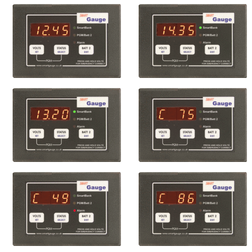
    If you want a proper job meter get a SmartGauge or a Trimetric.
    At the very least get a digital panel mount with 0.3% accuracy, three digit display.
    At the very very least an ebay job with an adjustable trimpot because nothing you buy on ebay will be calibrated.

    I'd put the main battery monitor in the living area by the way. That's where you'll reference it most.


  • Posts: 5,238 ✭✭✭ [Deleted User]


    Simona1986 wrote: »
    I then connected the leisure battery to a mini fuse-box and connected the fuse-box to the cable running into the dash. You can see the split charging relay in the background, which charges the two batteries when the engine is running.

    Your charge cable is too small you're going to throttle the effectiveness of your alternator. I'd recommend 35mm² (which probably won't fit into that relay) off the top of my head. It ought to be spec-ed to 0.3% voltage drop between batteries.

    Although if you upgrade the cable you'll have to upgrade the relay, 30A isn't a whole lot at 12V. I'll pull ~60A down my cables with batteries at 60% SOC a stoopid absorption fridge running and a laptop charging.


  • Registered Users, Registered Users 2 Posts: 6,908 ✭✭✭Alkers


    Thanks for the replies! So, do you think it is not worthwhile installing so? The switching is of no real benefit to me, I have the unit already and the main benefit of it to me would be the charge indicator, if there is a better way of knowing the state of the battery, I could go with that instead?
    I will have a look at the split charge relay again, what is the issue currently, is it dangerous or just going to be slow at charging?
    I must admit I'm rusty around the electrics side of things, not having done anything with them since my early in my undergrad.


  • Posts: 5,238 ✭✭✭ [Deleted User]


    For battery SOC you either need a Smartgauge or a shunted meter (ammeter or ammeter derived SOC meter) or both.

    sgamain01.gif


    This will do the Job. I use one and I find it indispensable.

    __57.150.JPG


    This might do the job if you have a penchant for the cheap and Chinesey

    $_12.JPG

    or another version (go for 100A minimum (1200W))

    $_12.JPG


    You can dead reckon it empirically with just a voltmeter time and an unloaded battery, or more accurately combined with an ammeter to monitor charge and discharge. Eg. if your 20A charger/80A alternator (correctly wired) is only pushing 2A then the battery is nearly fully charged. Or if your 200Ah battery is showing 11.8V with a 40A load then it's just under pressure and will bounce back.

    s-l225.jpg

    I don't like the red and blue LED displays though they make my eyes go all 3d vision.

    The problem with the Zig fuse block meter is it's el cheapo analogue which means it has a high margin for error even when calibrated. Also the scale is so narrow you can't tell what the actual reading is.

    The difference between a battery at 12.8v off load and 12.5v off load is 25% of your power or 50% of your usable power. So 0.3V is a difference of your electric fuel tank @ 100% or 50%. On a 12 volt scale to accurately measure the most significant digit (after the decimal) requires accuracy to 0.3%.


  • Posts: 5,238 ✭✭✭ [Deleted User]


    There's huge problems with alternator charging. It's as rare as hen's teeth to see it done right.
    The alternator by design is not a charger it's a generator it supplies power to electrical loads by observing the state of duress a battery is under. The battery leeches charge from the system that is not to say it charges. When it is heavily discharged it appears and behaves as a larger system load.

    It's as intelligent as a box of hammers but it can work like an elephant.

    To make an alternator a charger it needs vast quantities of copper.

    The problem being; it's regulated (cable) meters from the battery on cable, terminations, connections, switches, fuse holders, fuses that is effectively a resistor, it reads only the voltage of the tips of the wires attached to it's internal regulator. The best way to allow it to see the battery end of things is to use short direct runs with big cables that have effectively no resistance (<0.3% voltage drop at full load) so it can see the battery(s).

    The next problem with split charging is that the alternator will never see the true voltage of your leisure battery; only the voltage of the sum of your starter battery plus your leisure over 2 (or worse if you use diodes...really don't they're garbage for this purpose). So it's already producing half (ahem...half-ish..relative bank size, discharge level etc..) of what it ought in terms of charge current.

    There's a few ways around this.

    The best is two alternators with a redundancy switch, with big cables on the leisure side.

    The next is give it a (super-expensive) brain like a Sterling Battery to Battery charger they pop up here cheap every now and again.


    Sterling-waterproof-battery-to-battery-charger-12V-12V-60A.jpg

    The Sterling will still require a cable upgrade so best tackle that first, eh?

    The most prevalent is a relay switched by the dash charge indicator light but it's not unidirectional so the starter cannot be charged by other charging sources like PV or mains without further intervention.

    I use me noggin' and a switch that fires a 200A latching relay. When I abandon the vehicle I use a SmartBank because it's super intelligent and not limited to current as it has an external relay. All the kaboodle I pick up from this seller for buttons. He's on holliers but I know he has a few more in stock along with 200A previously loved state of the art relays...also for buttons.

    You can reroute your alternator B+ to be closer your leisure battery, but only start from your starter, with the auto-electric loads still on the starter side. This is finicky but worthwhile.

    The issue with your "heavy duty" VSR is it's not big enough for purpose in ampacity or mechanical strength to hold the cables you require for an alternator charger. It'll work as a generator and develop a feeble amount of charge and be safe if protected with two 30A fuses on the existing cables at each battery positive but you've lost most of your charge before you started.
    It takes at least 12 hours to charge a deep cycled battery, your alternator, usually does no more than 2 hours. You want it to work hard and fast. Expecting it to get cycled batteries over 85% is usually asking too much of it.

    My Mk-2 alternator charge circuit used to produce 7A max at the leisure battery. I'm on Mk-9 now and I've increased my harvest almost tenfold with just direct cabling on heavy conductors (and a bigger, faster, more better alternator). I reckon I could squeeze her to fifteenfold with enough dosh and desire.

    Alternators are only good at bulk charging they're fast and powerful but for the last 10% you need lots and lots and lots of time with diminishing current which is where a PV module rules the roost.

    Honourable mention.


  • Advertisement
  • Closed Accounts Posts: 1,040 ✭✭✭crabbypaddy


    Out of interest Liam how many wh are you getting this dreadful December.


  • Posts: 5,238 ✭✭✭ [Deleted User]


    No idea P. the bumblebee has been on mains float the last two weeks. I've a 110W panel angled 15° on the house that harvested roughly 10Wh today.
    I had 75Wp coming in on the solstice.
    I've been running on the alternator charge mostly since November, 600W is the most I've seen outta that but I can only check the Trimetric while the engine is idle (low RPM) because it's in the living compartment. Belt is still slipping a tad on startup...methinks I need to replace the pulley for the original...Summer Job.

    I can pull the log file but the alternator will probably have contaminated the data. Although I usually don't bother running the alternator through the charge controller these days unless I want extra oomph. The 200A relay does a much better job. They regulate about the same in absorption but the relay kicks bottom in bulk. [Edit: Relay wired on 35mm² cable, solar controller wired on 16mm² with a 40A breaker]

    Lowest the batteries have seen was 70% SOC because I fell asleep with the fridge running off the inverter. They're mostly sitting between 80% and 92% SOC.
    I'm taking her outtov port for a week tomorrow I'll let you know later.


  • Posts: 5,238 ✭✭✭ [Deleted User]


    Here ya go Simona state of the art split charge system for £35 plus cable.
    Don't wire the Smartbank live they get very upset if you put electrons in the wrong way round.

    Smartbank
    Product info

    Skookum Relay 200A Double Pole (spare ignition switched power feed).
    Datasheet

    You can buy a new one for £140.


  • Registered Users, Registered Users 2 Posts: 6,908 ✭✭✭Alkers


    Thanks for the replies, I will add the upgraded split charging and cables to my list of upgrades to make but unless it's dangerous it's going to be a bit further down my priorities. I don't have solar currently but it's probably in the pipework also.
    In the meantime, I'll probably pick up one of the Chinese meters so that I can have an indication as to the state of the LB.


  • Posts: 5,238 ✭✭✭ [Deleted User]


    For the best budget friendly mid-range charge system that will allow 9 months autonomy and the rest of the year give you a one week range and have the capability to run a compressor fridge is two alternators.

    If you're willing to forego the redundancy option of 2 x 12v alternators, 1 x 12v and 1 x 24v has great potential.

    All you need is an engine crank pulley that'll drive a second belt, someone to weld a well-aligned alternator bracket and alternator adjuster bracket on, a second hand 24v alternator with an adjuster and a belt.

    You'll need another charge indicator light (alternator won't work without it) and a dumb alternator that doesn't speak computer.

    So instead of having a split charge system you now have two charge systems. 4 times the power of a conventional camper at the same cost.

    24V makes a lot of sense, you still have the truck market for gizmos. You reduce your installation cable costs by a factor of 3. You have the same watts.

    2 X Banner Batteries wired series 24V: if you have moderate to light loads at duration.
    4 x Trojan T105s in series 24V: for a compressor fridge and moderate loads.

    Next up Bogart Engineering Trimetric and Solar Charger.

    Then a 250W/300W domestic solar panel. This is where 24V shines. Due to markets and fabrication costs you can get 250W solar @ 24v for the same price as 120W @ 12v.


    If you want to use that Zig voltmeter as a charge indicator (and that's all it's good for) you can demount it from the panel by removing the two nuts on the spreader and it should pop out. Then wire a 1A fuse onto the battery to the common terminal of a switch and link the switched terminal of the switch to the meter red wire. Meter white to chassis or battery negative.

    The 30A VSR will be safe if the starter battery positive is fused at the starter battery terminal with a 30A fuse, the leisure battery positive is fused at the leisure battery terminal with a 30A fuse, both those cables are on stranded 30A cable (> 3mm²) that's mechanically and thermally insulated. The switched/sense wires also need fuses according to their cable CSA.

    popcorn1-smiley.gif


  • Advertisement
  • Posts: 5,238 ✭✭✭ [Deleted User]


    Mwa! I've just thought of a redundancy / dirty start assist for a 12V / 24V setup;

    Centre tap the 24V battery to a relay and parallel to the starter battery. fight11.gif


  • Registered Users, Registered Users 2 Posts: 6,908 ✭✭✭Alkers


    Here ya go Simona state of the art split charge system for £35 plus cable.
    Don't wire the Smartbank live they get very upset if you put electrons in the wrong way round.

    Smartbank
    Product info

    Skookum Relay 200A Double Pole (spare ignition switched power feed).
    Datasheet

    You can buy a new one for £140.


    @Liamalot - so I never did anything with the leisure battery setup, even with your recommendations.

    Space is limited on the van and I only have room for one leisure battery under the bonnet - which means I can't run with the 12v & 24v setup as you recommended before. I also don't think there's any way I could get a second alternator connected given the mid-engine location so I'm pretty much left with a split-charge setup.

    The existing leisure battery was only 60Ah but people have fit up to 100Ah in the battery tray although I'll have to measure. Bearing in mind that the van is really only used for weekends away and anything longer we'll be using campsites (no toilet/shower!), if you see any other more-suitable split-charge setups, please do shout! Solar is on the wishlist down the line but no immediate plans, especially as we don't have a fridge as of yet!

    Thanks!


  • Registered Users, Registered Users 2 Posts: 6,908 ✭✭✭Alkers


  • Posts: 5,238 ✭✭✭ [Deleted User]


    Instantaneous rated Overrated rebranded junk. 50A max. Non-adjustable, dumb as a bag of hammers.

    s-l1000.jpg

    I recommend Merlin Smartbank Standard you can use any electro-mechanical relay with it.

    The NHS use it in their ambulances, easy find used ones.

    Your service battery can be relocated anywhere you want if you spec the right cable, larger capacity is possible with some creative wiring.


  • Registered Users, Registered Users 2 Posts: 851 ✭✭✭autumnalcore


    Simona1986 wrote: »

    Looks like a clone of the durite / altec one and the solder pads for the relays look suspiciously weedy, its got a better cut in voltage than the durite though which cuts in at 13.3v so if you install solar further down the line it can be clicking in and out all the time.

    No point in putting in a 140A relay unless you have decent cabling, how long is the cable to the alternator and what cross section is it.


  • Posts: 5,238 ✭✭✭ [Deleted User]


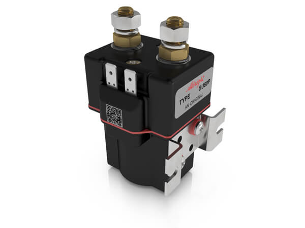
    It's not a 140A relay!
    It'll fail at 80A continuous. If anyone wants to send me one to prove it I'll happily document the meltdown.


    SU80P.jpg

    This is a 150A Contactor.


  • Registered Users, Registered Users 2 Posts: 6,908 ✭✭✭Alkers


    The NHS use it in their ambulances, easy find used ones.
    Great, I'll keep an eye out - how much are we talking?
    Your service battery can be relocated anywhere you want if you spec the right cable, larger capacity is possible with some creative wiring.
    It's in the bongo so there's no alternate space - engine is under the front seats and space limited in the rear. One battery should do me!
    No point in putting in a 140A relay unless you have decent cabling, how long is the cable to the alternator and what cross section is it.

    The cabling is no more than 1.5m and I am going to replace it with the new relay. The existing relay and cabling is very small!

    EDIT: Sorry, I thought you meant the cabling between the engine and leisure batteries. I haven't checked the stock alternator wiring!


  • Posts: 5,238 ✭✭✭ [Deleted User]


    I get them for ~£20 and contactors ~£15 when they pop up.
    I have a horde.

    PM sent.


  • Registered Users, Registered Users 2 Posts: 851 ✭✭✭autumnalcore


    The albright would outlive the van great investment but playing devils advocate 80a continuous is never going to happen you'd lucky to see 40a for 5 mins with a single leisure battery and a bongo alternator.


  • Posts: 5,238 ✭✭✭ [Deleted User]


    you'd lucky to see 40a for 5 mins with a single leisure battery and a bongo alternator.

    Agreed. Does that make it ok to lie about a device's capability?

    Used Albright are head and shoulders better than automotive relays.
    An SW60 is all you need, good conductivity, less coil consumption. Puts the competition to shame.

    The best split charge contactors are magnetic latching.


  • Advertisement
  • Registered Users, Registered Users 2 Posts: 6,908 ✭✭✭Alkers


    So I've ordered the smart bank as recommended by Liamalot!

    This is the unit its replacing!
    https://www.amazon.co.uk/Smartcom-Voltage-Sensing-Motorhome-Charging/dp/B00SGFTR2S

    Which was connected to a 60Ah battery which is goosed and the cables are very small. I'll be looking to pickup a new battery also but I'm limited by my tray which is only 30cm * 20cm - are there any sites where you can search leisure batteries by physical size?

    Looking at the smartbank wiring diagram:
    http://www.smartgauge.co.uk/sb_wiring.html
    • What gauge of cable should I use to run between the batteries (diagram specifies heavy duty cables)
    • Is there a particular relay that would be recommended for connecting on the +ive cable?

    Really appreciate the help!


  • Posts: 5,238 ✭✭✭ [Deleted User]


    Simona1986 wrote: »
    One battery should do me!

    Firefly are a good option if space is at a premium.
    92.8Ah Usable
    1000 Cycles to 80% Discharge
    €0.36 per kWh extracted to 80% DOD
    €0.19 per kWh extracted to 50% DOD

    Golf Cart Batts are
    €0.24 per kWh extracted to 50% DOD


    Simona1986 wrote: »
    This is the unit its replacing!

    Huzzah!
    Simona1986 wrote: »

    are there any sites where you can search leisure batteries by physical size?

    battery-group.jpg

    Simona1986 wrote: »

    • What gauge of cable should I use to run between the batteries (diagram specifies heavy duty cables)


    16mm² Red Thin Wall Automotive Cable
    Crimped Tinned Copper Lug Ends with Heatshrink over the bucket.
    Rubber Booted Post Covers
    Flexible Split Conduit

    Simona1986 wrote: »

    • Is there a particular relay that would be recommended for connecting on the +ive cable?


    I recommend this one.
    with a mounting bracket.

    Datasheet.


    This is the least you can do.
    This is probably what's inside the "140A" VSR

    Remove EHU & Disconnect All Batteries before commencing work.
    Take a new feed from the alternator and stack the lugs so it is Service Battery on bottom Engine Battery on top.
    Alternator -> Contactor -> 100A Maxi Blade Fuse (battery end)-> Service Battery
    Support cabling with rubberised stainless P-Clips and Rivnuts or tie into existing looms.
    Put the Smartbank inside the cab or in a waterproof enclosure with sealed entries.
    Wire Smartbank as instructed in manual.
    If the Service Battery Chassis Ground is less than 16mm² then make it 16mm² to chassis. Connect it to whatever the Engine Battery Ground is connected to. Stack Engine Battery on top of Service Battery.

    If opportunity arises put the 12volt side of your fridge on the Engine Battery with 6mm² and relay switch it from the D+.
    This will boost charge to the Service Battery (Alternator regulator senses greater load) and remove running load to Habitation Electrics at the same time.


  • Registered Users, Registered Users 2 Posts: 6,908 ✭✭✭Alkers


    Thanks for the detailed reply!

    Getting there....
    I will order the recommended relay and bracket, do you know of any decent supplier around Dublin / online for the cabling and connectors? I was going to order from that same supplier but they only do 10m lengths which adds up quickly!

    By that battery size guide, I will struggle to fit the 27 size (6mm off the length) so I'll have to measure more-accurately and see if I can fit them in before choosing a battery.


  • Registered Users, Registered Users 2 Posts: 6,908 ✭✭✭Alkers


    Simona1986 wrote:
    By that battery size guide, I will struggle to fit the 27 size (6mm off the length) so I'll have to measure more-accurately and see if I can fit them in before choosing a battery.


    So the battery group 27 will fit my tray. The firefly battery won't fit but I could only find us suppliers for 400+$ in any case!


  • Posts: 5,238 ✭✭✭ [Deleted User]


    10m is standard length. You might get welding cable cut per metre.
    30m for two core and 100m for mains flex. Smaller lengths will be astronomical prices.

    You can mount AGM sideways. I will refabricate the battery tray to shoe-horn in a battery if needs be.

    $400 is what they cost. Hence I did the kWh lifetime calc because you won't find better outside of forklift cells.


  • Registered Users, Registered Users 2 Posts: 6,908 ✭✭✭Alkers


    $400 is what they cost. Hence I did the kWh lifetime calc because you won't find better outside of forklift cells.

    How does this: https://www.alpha-batteries.co.uk/24-tmx-trojan-deep-cycle-battery/ stack up as a compromise? I just can't justify spending €400 (nor can I find a non-US supplier!)


  • Posts: 5,238 ✭✭✭ [Deleted User]


    The flooded TMX is probably the best battery you can get. Its more expensive than golf carts though and doesn't perform as well.

    CycleLife-RE-sign.png


  • Registered Users, Registered Users 2 Posts: 6,908 ✭✭✭Alkers


    Thread revival.

    I've had this setup for the last few months, not really tested for anything more than the odd overnight but all working good (still stock cables from alternator).
    Wire Smartbank as instructed in manual

    I showed a friend the setup and he queried the lack of fuses between the batteries and the relay, anyone weigh in on that one? I've seen examples both way online.

    www.smartgauge.co.uk/scheme.html


  • Registered Users, Registered Users 2 Posts: 851 ✭✭✭autumnalcore


    Simona1986 wrote: »
    Thread revival.

    I've had this setup for the last few months, not really tested for anything more than the odd overnight but all working good (still stock cables from alternator).


    I showed a friend the setup and he queried the lack of fuses between the batteries and the relay, anyone weigh in on that one? I've seen examples both way online.

    www.smartgauge.co.uk/scheme.html

    Yep. Should be fused as close to the batteries as practicable. The website and diagram appear to have timetravelled from the 90's though was there not something more up to date in the box?


  • Advertisement
  • Posts: 5,238 ✭✭✭ [Deleted User]


    was there not something more up to date in the box?


    421723.jpg


Advertisement