Advertisement
If you have a new account but are having problems posting or verifying your account, please email us on hello@boards.ie for help. Thanks :)
Hello all! Please ensure that you are posting a new thread or question in the appropriate forum. The Feedback forum is overwhelmed with questions that are having to be moved elsewhere. If you need help to verify your account contact hello@boards.ie

Wiring advice on extractor fans

Options
  • 11-06-2013 1:32pm
    #1
    Registered Users Posts: 33


    I am replacing two ceiling mounted extractor fans (en-suite and bathroom) because they drip cold water on bath/shower users when the rooms are steamed up and don't work very well.

    (Incidentally for anyone with a similar problem - the cure may be as simple as ensuring a sufficient gap under the door to allow the vents to work properly - but I was too far down the road when I noticed there were virtually no gaps under the doors)

    I drilled new ~100mm wall vents - the en-suite fitting will be in Zone 3 so I'm using a mains powered fan with timer and humidity detector, however the bathroom vent is on Zone 2 so I'm using a low voltage fan with timer for that (23W).

    I wasn't happy with the existing wiring as the units were not fused and did not have isolation switches and used universal connectors for taps so starting from scratch..

    My plan is to
    > tap into lighting mains feed live/neutral in the attic using a junction box and distribute that via 1.5 t&e to two seperate 3amp fused spur units (one for each fan cct. (fitting the fused units in the attic which is partially floored)
    > from each fused spur unit... feed mains & neutral on 1.5 t&e to 3 pole fan isolation switches fitted outside the relevant rooms above the light switches at about top of door height (expect they will be left permanently on unless there is an issue)
    > tap a feed from the light switches 'switched live' to the 3 pole isolation switch 'switched live' terminals
    >for the ensuite - wire the 3 isolation switch outputs directly to the mains fan extractor fan using 1.5 and job is done using (no earth connections as fan unit is twin insulated)
    >for the bathroom - wire the 3 pole isolation switch outputs to the low voltage control/transformer unit inputs (fitted in the attic) again using 1.5 t&e (no earth). Then connect the two control unit outputs (12v A/C 1.670mA) to the fan using alarm wire.

    My questions...
    > Is it ok to fit the fused units in the attic or am I breaking a regulation? (I really don't want to fit another unsightly unit on the walls outside each room)

    > Can I use just one fused spur unit to feed both ccts and if is so should I change the 3amp fuse to something else? or should I stick with one each?

    > Is it ok to use single cores of alarm wire (I'm guessing its 22 gauge but I don't know for sure) to connect the low voltage 12V A/C 1.670mA or should I double up on the cores or use some other cable?

    > Am I doing anything else wrong?

    Any help would be greatly appreciated


Comments

  • Closed Accounts Posts: 699 ✭✭✭mikehammer67


    i'd say there's a few issues with your method anyhow

    fusing the perm feed but not the switched live
    not connecting cpc(earth) on the t&e
    no cpc(earth) at fused spur terminals

    i wouldn't use the alarm wire for fan-prob 2-core flex or the like
    singles is prob better if you've no earth available


  • Registered Users Posts: 33 POE101


    Many thanks mikehammer67...

    "fusing the perm feed but not the switched live"
    You are absolutely right - on looking again at the wiring diagrams that came with the low voltage unit I need to replace existing live feeds to light switches with feed from the fused spurs instead.

    "not connecting cpc(earth) on the t&e"
    I'm guessing the issue with using t&e and cutting the earths away is that someone could come along later and tap in somewhere thinking they have and earth or that damage to the wire could result in live on the exposed/unearthed earth?

    "no cpc(earth) at fused spur terminals"
    Point taken - if there is an earth available I will pick it up or go with your suggestion for singles

    "2-core flex or the like"
    Will do

    Thanks again for the response!


  • Closed Accounts Posts: 699 ✭✭✭mikehammer67


    some timer fans will specify fusing them at 3amp

    i don't think there's any proper way of doing that without keeping control of the fan independent of light

    ie:supply to 3amp fcu > isolator > fan


    wiring bathroom light and fan from 3amp spur would be BAD PRACTICE

    there's also rules on providing cpcs at electrical points and rcd protection on circuits in zones(wouldn't apply to a ELV fan though)


  • Registered Users Posts: 33 POE101


    "wiring bathroom light and fan from 3amp spur would be BAD PRACTICE "

    That leaves me in a dilema...

    This is the diagram from the low voltage unit that shows exactly that...
    obaraht
    (don't have the mains one to hand)
    Elswhere the manual has a coverall something like "must be wired according to local regulations"

    Test extract from manual re wiring...
    qe6zwlb
    doesn't actually specify a spur unit though.


  • Closed Accounts Posts: 699 ✭✭✭mikehammer67


    most sparks prob don't bother with 3amp FCU-that simplifies the control and wirng

    if a timer fan requires a 3amp fcu which some do afaik -there's prob no correct method of wiring it without having it controlled separate to light

    not that i can think of anyhow


  • Advertisement
  • Moderators, Home & Garden Moderators, Technology & Internet Moderators, Regional East Moderators Posts: 12,546 Mod ✭✭✭✭2011


    POE101 wrote: »
    "wiring bathroom light and fan from 3amp spur would be BAD PRACTICE "

    That leaves me in a dilema...

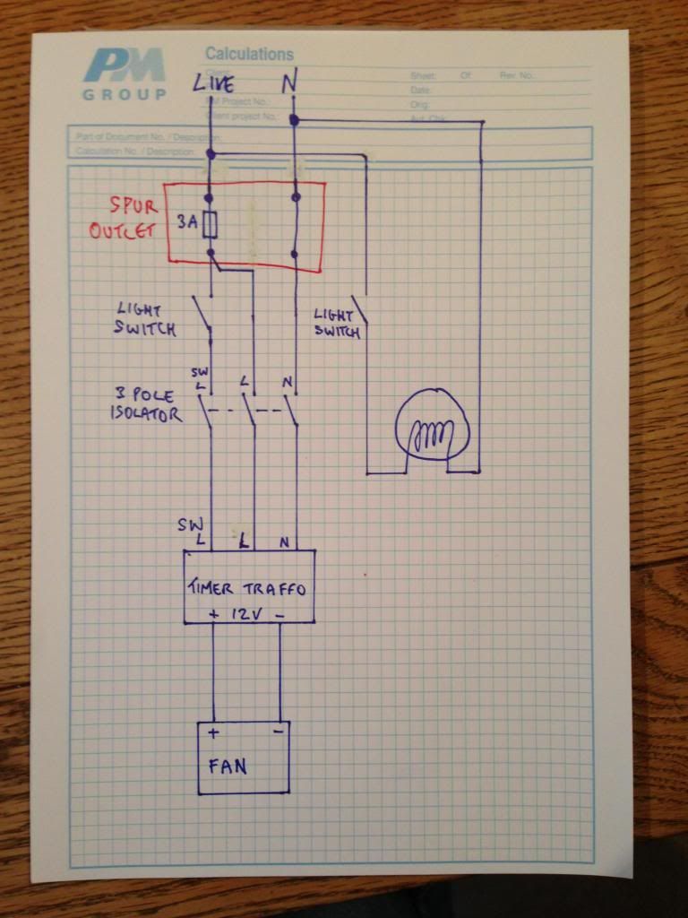
    Not really, try this:

    Fan.jpg


  • Closed Accounts Posts: 699 ✭✭✭mikehammer67


    well ya obviously he can wire it independently...as i already said

    but he won't have fan come on with light


  • Moderators, Home & Garden Moderators, Technology & Internet Moderators, Regional East Moderators Posts: 12,546 Mod ✭✭✭✭2011


    well ya obviously he can wire it independently...as i already said

    but he won't have fan come on with light

    Why not? He could simply use a double pole switch (sorry, forgot to mark it as such).


  • Closed Accounts Posts: 699 ✭✭✭mikehammer67


    2011 wrote: »
    Why not? He could simply use a double pole switch (sorry, forgot to mark it as such).
    yes although he's prob on a refurb -might be awkward


  • Moderators, Home & Garden Moderators, Technology & Internet Moderators, Regional East Moderators Posts: 12,546 Mod ✭✭✭✭2011


    yes although he's prob on a refurb -might be awkward

    If it was easy sure wouldn't everyone be doing it :)

    The trick is to give the end user exactly what they require and comply with the regulations, nobody said that there would always be a convenient solution.


  • Advertisement
  • Registered Users Posts: 33 POE101


    I see said the blind man... :-) nice diagram 2011! That seems to take care of the bathroom cct

    So in relation to the the mains fan unit in Zone 3 of the en-suite and "rules on providing cpcs at electrical points and rcd protection on circuits in zones"

    Do I need to do something extra there too or can I go with just wiring as per diagram but substituting direct feed from 3 pole isolation to the fan unit?


  • Closed Accounts Posts: 699 ✭✭✭mikehammer67


    ya 2011s DP switch solution solves your problem with fusing and overrun-missed the obvious there!


    -i just raised the issue of cpcs at points-as it's neither standard practice to use singles only or cut-off the earth on t&e

    -also regulations specify rcd protections for circuits in bathroom zones(not relevant to
    12v fan)

    -they're not really safety issues here if it's diy for yourself


  • Registered Users Posts: 33 POE101


    Many thanks for all the help - it looks like it is going to be hard to find a single gang two pole switch (bathroom) and a two gang two pole switch (en-suite) - they dont seem to be commonly available.

    So finally - if you have any ideas on where I might find them easily it would be appreciated. (Im in Lucan)


  • Moderators, Home & Garden Moderators, Technology & Internet Moderators, Regional East Moderators Posts: 12,546 Mod ✭✭✭✭2011


    I would use MK DP switches. Easily available in most electrical wholesaler.
    Google ND electrical, Eurosales or Kellighers.


  • Registered Users Posts: 33 POE101


    I now have the two fans wired and working :-) again many thanks for the contributions!

    In the process I came across something that bothers me and need some more advice...

    While isolating ccts at the consumer board I found that the ccts marked Kitchen Sckts, Downstairs Sckts and Upstairs Sckts all appear to be crossed. i.e. if want to kill power to the Kitchen sockets I have to kill ALL THREE breakers (turning any one of these on while the other two are off provides power to the kitchen). I can only assume that all three rings have been mixed up.

    Is there any valid reason why this would be done? I'm asking because I found something similar in my own house 13 years ago when I moved in (I found two ccts crossed) and am now wondering if I'm wrong - surely the two live ends of any ring cct should terminate on the same breaker?.


  • Closed Accounts Posts: 13,422 ✭✭✭✭Bruthal


    POE101 wrote: »
    I now have the two fans wired and working :-) again many thanks for the contributions!

    In the process I came across something that bothers me and need some more advice...

    While isolating ccts at the consumer board I found that the ccts marked Kitchen Sckts, Downstairs Sckts and Upstairs Sckts all appear to be crossed. i.e. if want to kill power to the Kitchen sockets I have to kill ALL THREE breakers (turning any one of these on while the other two are off provides power to the kitchen). I can only assume that all three rings have been mixed up.

    Is there any valid reason why this would be done? I'm asking because I found something similar in my own house 13 years ago when I moved in (I found two ccts crossed) and am now wondering if I'm wrong - surely the two live ends of any ring cct should terminate on the same breaker?.

    Sounds like the ends of ring circuits are mixed up alright, assuming no mad wiring setup is linking socket circuits together around the house.

    The ends of ring main circuits should/must be connected into the same breaker.


  • Moderators, Home & Garden Moderators, Technology & Internet Moderators, Regional East Moderators Posts: 12,546 Mod ✭✭✭✭2011


    Time for a qualified electrician in my opinion, use a Registered Electrical Contractor would be my advice. If a fundamental mistake like that has been made God only knows what else is wrong.

    This clearly falls under the defenition of restricted works


  • Closed Accounts Posts: 13,422 ✭✭✭✭Bruthal


    2011 wrote: »

    This clearly falls under the defenition of restricted works

    Come with me Bruthal, your under arrest on suspicion of replacing a 10 amp MCB


  • Moderators, Home & Garden Moderators, Technology & Internet Moderators, Regional East Moderators Posts: 12,546 Mod ✭✭✭✭2011


    Bruthal wrote: »
    Come with me Bruthal, your under arrest on suspicion of replacing a 10 amp MCB

    Clearly there are some issues with the way the distribution board has been connected. In my opinion (and I am not alone) this issue should only be dealt with by a qualified electrician. Mistakes left like this mean that it is highly probable that there are other (possibly more serious) issues with the Op's electrical installation. I would think it prudent to employ a professional to at least give an opinion on the installation, particularly the distribution board. Some may disagree and decide to take a chance and "save" money by attempting to take on this work themselves despite having a lack of experience or training, but I would think that this may well cost them in more ways than one /Rant :)


  • Closed Accounts Posts: 13,422 ✭✭✭✭Bruthal


    2011 wrote: »
    Clearly there are some issues with the way the distribution board has been connected. In my opinion (and I am not alone) this issue should only be dealt with by a qualified electrician. Mistakes left like this mean that it is highly probable that there are other (possibly more serious) issues with the Op's electrical installation. I would think it prudent to employ a professional to at least give an opinion on the installation, particularly the distribution board. Some may disagree and decide to take a chance and "save" money by attempting to take on this work themselves despite having a lack of experience or training, but I would think that this may well cost them in more ways than one /Rant :)

    Yea, but I never suggested a non qualified person do any work. Restricted works stuff makes qualified electricians no longer qualified, except maybe to change light bulbs. That was the point I was (jokingly) making. I must be typing in chinese again.


  • Advertisement
  • Closed Accounts Posts: 699 ✭✭✭mikehammer67


    that is so careless-i always run through the breakers one at a time when finishing up
    and confirm dead on outgoing side when off

    just a habit of mine


    time for an inspection


  • Closed Accounts Posts: 13,422 ✭✭✭✭Bruthal


    that is so careless-i always run through the breakers one at a time when finishing up
    and confirm dead on outgoing side when off

    just a habit of mine

    Yes basic electrical common sense that one.

    It could be a later alteration rather than the original job that caused it.


  • Closed Accounts Posts: 699 ✭✭✭mikehammer67


    could be -pet hate of mine that one

    seen it lots of times

    some from new and some alterations

    can happen outside of the distribution board if there's 'monkey puzzle' wiring with junction boxes alright


  • Registered Users Posts: 33 POE101


    Points taken - time for a qualified electrician!

    It's difficult to believe such a fundamental thing could be done wrong, tested and passed. Begs the question are all the neighbour's houses wired incorrectly too...

    How far does the restricted works go? e.g. If an unqualified person replaces a socket in their own home are they breaking the law?


  • Moderators, Home & Garden Moderators, Technology & Internet Moderators, Regional East Moderators Posts: 12,546 Mod ✭✭✭✭2011


    POE101 wrote: »
    It's difficult to believe such a fundamental thing could be done wrong, tested and passed.
    ...well tested in theory. Self regulation is no regulation at all.
    How far does the restricted works go? e.g. If an unqualified person replaces a socket in their own home are they breaking the law?
    No.

    As detailed here:

    “Like for like” replacements of switches, sockets, lighting fittings and/or additions to an existing circuit is frequently carried out in this country. While this must also be in compliance with the Technical Rules, these types of electrical works sit outside the Defined Scope of Controlled Works.

    In my opinion (and I suspect Bruthal's) anyone with suitable qualifications (electrician) and experience should be permitted to carry out this sort of work once they have the necessary experience, understanding and test equipment.


  • Closed Accounts Posts: 13,422 ✭✭✭✭Bruthal


    2011 wrote: »
    In my opinion (and I suspect Bruthal's)

    :D

    So I am a suspect then....


Advertisement