Advertisement
If you have a new account but are having problems posting or verifying your account, please email us on hello@boards.ie for help. Thanks :)
Hello all! Please ensure that you are posting a new thread or question in the appropriate forum. The Feedback forum is overwhelmed with questions that are having to be moved elsewhere. If you need help to verify your account contact hello@boards.ie
Hi there,
There is an issue with role permissions that is being worked on at the moment.
If you are having trouble with access or permissions on regional forums please post here to get access: https://www.boards.ie/discussion/2058365403/you-do-not-have-permission-for-that#latest

Wiring central heating system

  • 03-05-2013 12:36am
    #1
    Registered Users, Registered Users 2 Posts: 52 ✭✭


    Just wondering if any1 could explain to me how to wire a domestic central heating system ??? Have not had experience doing them so I'd like to get up to date with the ins and outs of it


Comments

  • Closed Accounts Posts: 305 ✭✭kramer1


    Just wondering if any1 could explain to me how to wire a domestic central heating system ??? Have not had experience doing them so I'd like to get up to date with the ins and outs of it

    Depends on how its set up . You can have basic with just one zone and clock or a load of zones ,stats ,motorised valves etc.


  • Registered Users, Registered Users 2 Posts: 52 ✭✭Sparkobrien77


    kramer1 wrote: »
    Depends on how its set up . You can have basic with just one zone and clock or a load of zones ,stats ,motorised valves etc.

    Thanks for replying,just wondering say a normal gas boiler with two zones ch and hw,with stats and a programmer,what way would you wire them and what size cable and how many cores ??


  • Closed Accounts Posts: 13,422 ✭✭✭✭Bruthal


    Thanks for replying,just wondering say a normal gas boiler with two zones ch and hw,with stats and a programmer,what way would you wire them and what size cable and how many cores ??

    Wire to switched spur and then to timer. Also from spur to boiler. One timer zone output goes to room stat, then to motorised valve for radiators.

    Other timer output goes to immersion stat, and then to motorised valve on immersion coil. So the timer zone switches operate the zone motorised valves through the stats.

    The motorised valves have switches in them, via the grey and orange wires. Connect greys from both valves together, same with orange wires.

    In gas boiler there will be a link to be removed. Once removed it will not run even though boiler has power supply from spur all the time.

    You connect the greys into one of the terminals the link was in, and the orange wires into the other.

    So when either of the motorised valves comes on due to timer switching it, and stat is closed, its switch will close on the orange/grey wires, closing the link in boiler, and it fires boiler up. When stat or timer goes off, boiler pump continues to run, until boiler cools, or stat/timer calls boiler on again.

    If you meant 2 radiator zones and hot water, its same as above except 3 channel timer, with radiator zone repeated twice, timer to room stat, then to zone valve. 3 greys linked, and 3 oranges linked, and into boiler link terminals as above.


  • Registered Users, Registered Users 2 Posts: 924 ✭✭✭jjf1974


    There are some videos here on wiring gas boilers that might help http://www.plumberparts.co.uk


  • Advertisement
  • Registered Users, Registered Users 2 Posts: 270 ✭✭liveandnetural


    have a look at fishdogs diagram in the stickys


  • Closed Accounts Posts: 13,422 ✭✭✭✭Bruthal


    have a look at fishdogs diagram in the stickys

    That diagram shows the live linked from the supply spur to the motorised valve switches. On boilers now, that's not needed. The valve switches connect across the boilers control link.

    In effect, on most, it is simply taking the live from a loop from the live supply terminal, through the valve switches, and return to the other link terminal.

    Best to use the boilers 2 terminals anyway.

    Other than that, that diagram is how its done.


  • Registered Users, Registered Users 2 Posts: 1,884 ✭✭✭Robbie.G


    Bruthal wrote: »
    That diagram shows the live linked from the supply spur to the motorised valve switches. On boilers now, that's not needed. The valve switches connect across the boilers control link.

    In effect, on most, it is simply taking the live from the link terminal, through the valve switches, and return to the other link terminal.

    Best to use the boilers 2 terminals anyway.

    Other than that, that diagram is how its done.
    Not all boilers are volt free switching.
    If volt free as you stated if normal voltage switching as the diagram.


  • Closed Accounts Posts: 13,422 ✭✭✭✭Bruthal


    Robbie.G wrote: »
    Not all boilers are volt free switching.
    If volt free as you stated if normal voltage switching as the diagram.

    Most modern gas boilers have a link to be removed. The second terminal of the 2 could be fed as per the diagram, as the first terminal is simply a link from the live supply terminal anyway. The only volt free item is the valve switches before they are connected.

    But it is simply worth noting that when the boiler has a link, it should be removed and the loop completed through the motorized valve switches in parallel.


  • Registered Users, Registered Users 2 Posts: 1,884 ✭✭✭Robbie.G


    Bruthal wrote: »
    Most modern gas boilers have a link to be removed. The second terminal of the 2 could be fed as per the diagram, as the first terminal is simply a link from the live supply terminal anyway. The only volt free item is the valve switches before they are connected.

    But it is simply worth noting that when the boiler has a link, it should be removed and the loop completed through the motorized valve switches in parallel.
    Its grand when its a new job complete wire problem is when it's retrofitted if its volt free what I do is use a 240v relay to switch the boiler


  • Advertisement
  • Closed Accounts Posts: 13,422 ✭✭✭✭Bruthal


    Robbie.G wrote: »
    Its grand when its a new job complete wire problem is when it's retrofitted if its volt free what I do is use a 240v relay to switch the boiler

    The op was asking how to wire a gas boiler using motorised valves and 3 channel timeclock probably.

    Relay is a good idea for when just a switch wire is available alright. Used them once or twice for that myself.


  • Registered Users, Registered Users 2 Posts: 1,884 ✭✭✭Robbie.G


    Bruthal wrote: »
    The op was asking how to wire a gas boiler using motorised valves and 3 channel timeclock probably.

    Relay is a good idea for when just a switch wire is available alright. Used them once or twice for that myself.
    I post a linking wiring diagrams for that reason.One thing everyone should watch that under current law it's illegal for anyone other than a rgi to work on a gas boiler that includes the electrics.So to cover yourself just do your wiring to a 3pole isolator at the boiler


  • Closed Accounts Posts: 13,422 ✭✭✭✭Bruthal


    Robbie.G wrote: »
    I post a linking wiring diagrams for that reason.One thing everyone should watch that under current law it's illegal for anyone other than a rgi to work on a gas boiler that includes the electrics.So to cover yourself just do your wiring to a 3pole isolator at the boiler

    Yea, and leave the wiring to the gas man.

    A licence to own a phase tester is next.


  • Banned (with Prison Access) Posts: 698 ✭✭✭belcampprisoner


    which one


  • Registered Users, Registered Users 2 Posts: 1,884 ✭✭✭Robbie.G


    Bruthal wrote: »
    Yea, and leave the wiring to the gas man.

    A licence to own a phase tester is next.

    As you know similar is coming in for rec's
    All I'm saying is its illegal for anyone other than a rgi to take the cover off a gas boiler Rgii is in the process of prosecuting someone for changing a circulating pump as it was internal.
    And anyone gas man of not should be well capable of wiring a s plan sure you could teach it to anyone in an other or two


  • Registered Users, Registered Users 2 Posts: 1,428 ✭✭✭Dotsie~tmp


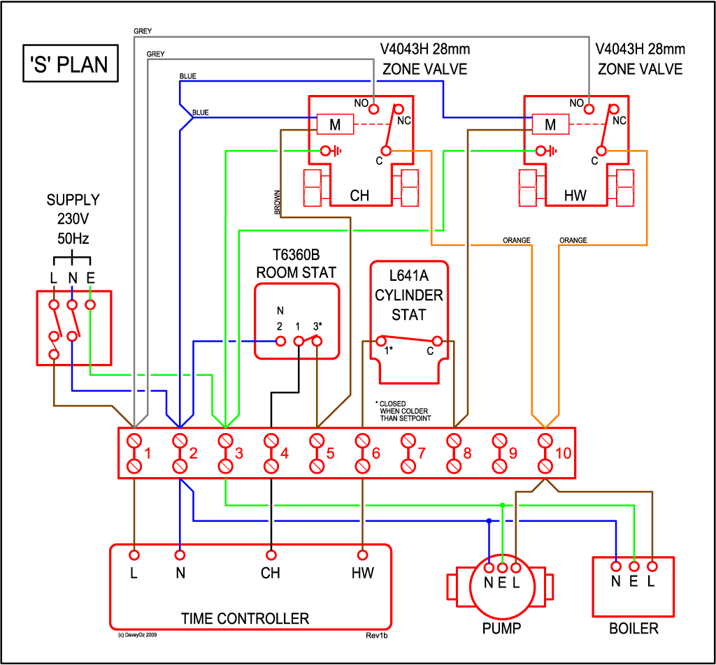
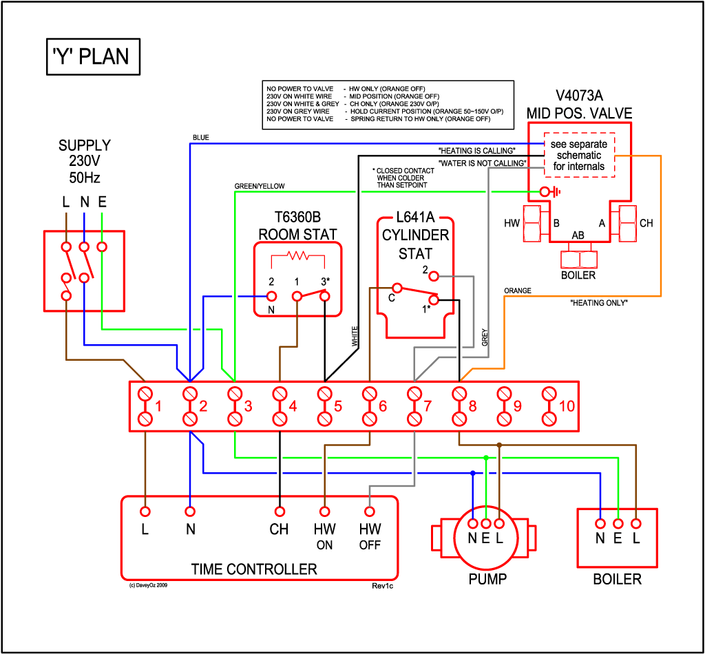
    http://wiki.diyfaq.org.uk/index.php?title=Central_Heating_Controls_and_Zoning

    S-plan and Y-plan are your most common. Ask the plumber which one.

    S-Plan-Wiring.gif

    Y-Plan-Wiring.gif

    Run plenty on cores from clock to main joint box by cylinder. Then all stats and valves 4 cores to main JB. 4 core from clock to boiler. Keep the spur that feeds near the clock and boiler 5 amp. That should cover wires then just follow a diagram above. Or use a smart system with plumber and forget about all of this bar the spur.

    Ps. The diagrams are 2 zone but can be expanded by just replicating a CH out put through a stat.


  • Closed Accounts Posts: 13,422 ✭✭✭✭Bruthal


    Dotsie~tmp wrote: »
    http://wiki.diyfaq.org.uk/index.php?title=Central_Heating_Controls_and_Zoning

    S-plan and Y-plan are your most common. Ask the plumber which one.


    Run plenty on cores from clock to main joint box by cylinder. Then all stats and valves 4 cores to main JB. 4 core from clock to boiler. Keep the spur that feeds near the clock and boiler 5 amp. That should cover wires then just follow a diagram above. Or use a smart system with plumber and forget about all of this bar the spur.

    Ps. The diagrams are 2 zone but can be expanded by just replicating a CH out put through a stat.

    The s plan there, which is the likely one for the op, is switching the boiler and pump straight on and off whenever the room stat/cylinder stat operates, or when timeclock goes off, probably not what will be wanted with a system gas boiler, particularly with no pump over-run setup.

    It is the same control setup as the ones mentioned earlier, except that they have grey and orange wires connected across the terminals in boiler where a link is removed. And the boiler has a permanent connected L, N, E. So when the control loop opens, the boiler`s pump can continue to run to dissipate heat.


  • Registered Users, Registered Users 2 Posts: 52 ✭✭Sparkobrien77


    Thanks for all the info,one last thing would you have a 6amp mcb on the rcd side of the board or not ?


  • Closed Accounts Posts: 699 ✭✭✭mikehammer67


    domestic heating pumps require rcd protection

    so you'll prob fit rcd side or rcbo


  • Registered Users, Registered Users 2 Posts: 378 ✭✭frankmul


    domestic heating pumps require rcd protection

    so you'll prob fit rcd side or rcbo

    Is there need for a RCD on the circ pump?. When did that come in


  • Advertisement
  • Closed Accounts Posts: 699 ✭✭✭mikehammer67


    i think it's in there et:101 2008 ,dont have it handy


    certainly should be anyhow


  • Registered Users, Registered Users 2 Posts: 1,884 ✭✭✭Robbie.G


    There is a trainning course for heating wiring been run shortly here's the details if anyone's interested.Before anyone asks I have novonnection it was sent to me so just passing it on
    https://www.dropbox.com/s/xf9xqsgp2tsnl3a/Electrical%20Course%20Flyer2.pdf


  • Registered Users, Registered Users 2 Posts: 378 ✭✭frankmul


    i think it's in there et:101 2008 ,dont have it handy


    certainly should be anyhow

    I thought it was just immersions and electric showers that need rcd protection, is it anything that is in contact with water?


  • Closed Accounts Posts: 699 ✭✭✭mikehammer67


    frankmul wrote: »
    I thought it was just immersions and electric showers that need rcd protection, is it anything that is in contact with water?


    555.3.2 i think maybe that's the rule

    i just assumed it was a rule without knowing which one

    dom pumps should certainly have rcd anyway


Advertisement