Advertisement
If you have a new account but are having problems posting or verifying your account, please email us on hello@boards.ie for help. Thanks :)
Hello all! Please ensure that you are posting a new thread or question in the appropriate forum. The Feedback forum is overwhelmed with questions that are having to be moved elsewhere. If you need help to verify your account contact hello@boards.ie
Hi there,
There is an issue with role permissions that is being worked on at the moment.
If you are having trouble with access or permissions on regional forums please post here to get access: https://www.boards.ie/discussion/2058365403/you-do-not-have-permission-for-that#latest

Just built a touch key for CW

  • 23-04-2013 2:12pm
    #1
    Registered Users, Registered Users 2 Posts: 2,045 ✭✭✭


    so..... I have motor issues and I love me a bit of CW, so I needed something better (well, less impactful) than a regular straight key.

    mk1 ....

    I made a side swipe paddle from a kitchen knife and a few screws and bolts from B&Q.

    not bad, but I can do better......

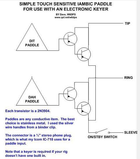
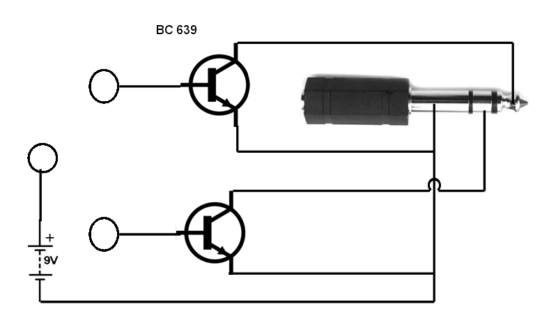
    I found this circuit on the net.

    TP_paddlescheme.jpg

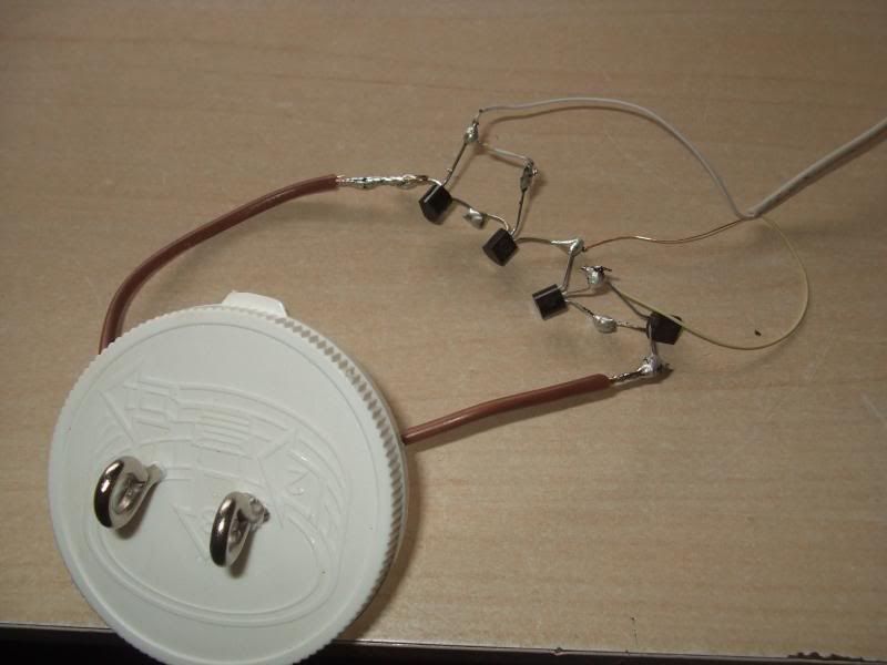
    so, I built it.

    Ham007-1_zps7a198c84.jpg

    tested it with the soldering iron still switched on.... worked fine.

    tested it again with the glue gun plugged it..... worked fine.

    tested it with all the electric stuff put away..... nuffin!

    with a PC power supply switched on beside it (not connected to anything) works fine.

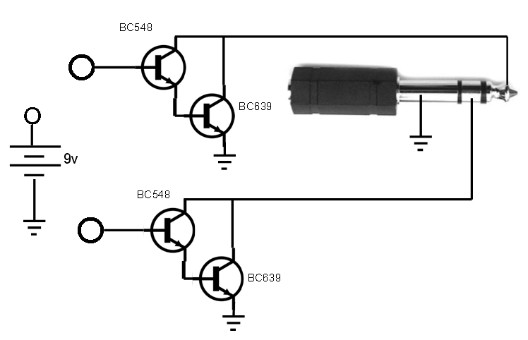
    so I need some power....

    add a battery.....


    touchkey_zps4e2b50b3.png
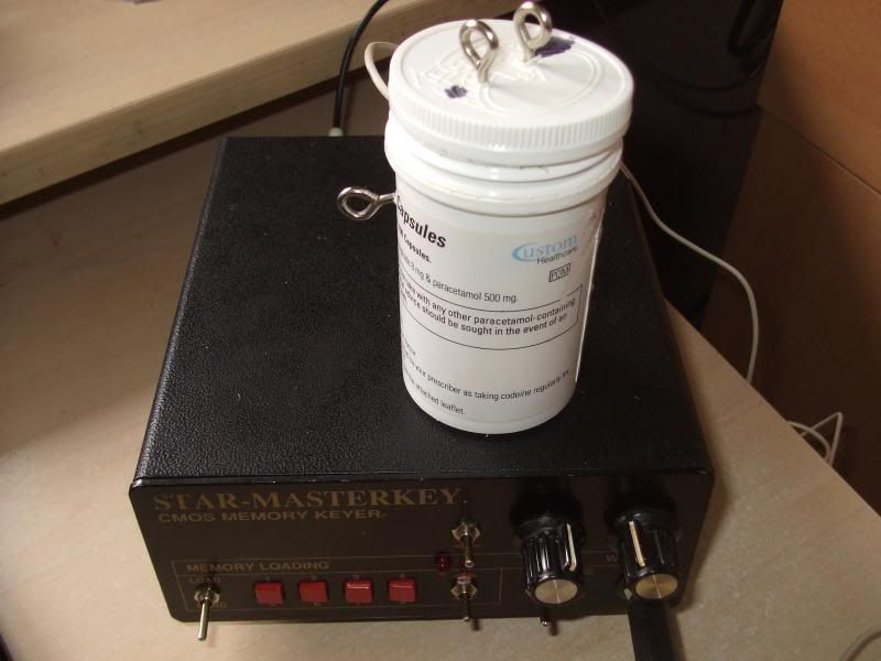
    and fit the whole lot inside a pill bottle. hold the case in your hand, and so long as you are touching the terminal, it works just dandy!

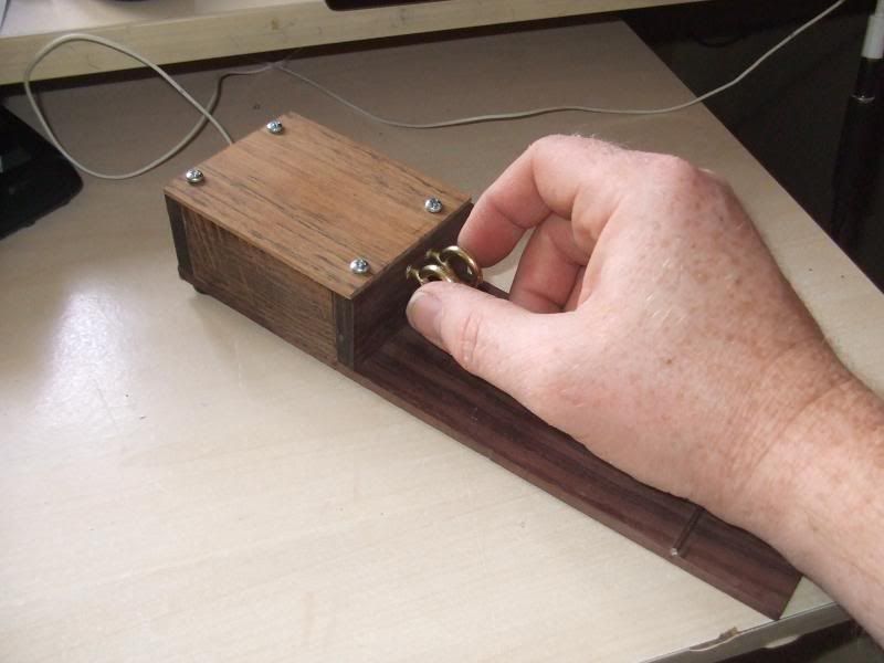
    if you send dits with your finger, have the earth terminal at the bottom. dits with your thumb, earth terminal at the top.

    Ham_zpsd39a9b06.jpg

    so, prototype works, next step is to make it for real.....

    what I'm THINKING is to have the earth spud on a panel in front of the touch plates.

    I have guitar fret wire, which I could press into a slot across the front so that where ever my hand sits, a good contact will be made.

    unless I'm wearing marigolds of course!!


Comments

  • Registered Users, Registered Users 2 Posts: 32,417 ✭✭✭✭watty


    I'd put 10K input series resistors, small capacitors (10pf) and 4M7 Ohm resistors from bases to 0V. It's too noise and RF sensitive as it is.

    If you use a pair of MosFETs, (BS170 etc) instead of 2 sets of Bipolar (still need protection but resistors on Gate to 0V can be 10M). Maybe then you can use 2 x Lithium coin cells and they would last 10 to 20 years. The PP3 will self discharge in about 1 to 2 years if Layer cell and 4 years if Alkaline.


  • Registered Users, Registered Users 2 Posts: 2,045 ✭✭✭martinedwards


    Thanks for that, next time!!

    I'm going to make a nice wooden case for this one in the mean time.

    I have some offcuts of rosewood laying in a box......


  • Registered Users, Registered Users 2 Posts: 2,045 ✭✭✭martinedwards


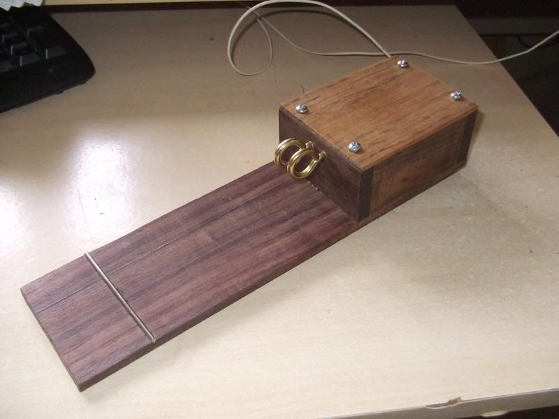
    so time to make a nicer container for it.

    as I have made a few guitars in my time I had some fret wire laying around.

    I reckoned a strip where my hand rests would be an improvement on the lug......

    so, some offcuts of rosewood, and ovankohl.......

    as I was assembling the whole thing I managed to break a leg off a tranny, so I tried it without the darlington pair, just a single BC639 on each side. Delighted to discover it works fine!!

    touchkeyercircuit_zps711bcdd0.png

    Ham156_zpsff4613eb.jpg

    Ham157_zps858c4b55.jpg

    toughest part of the whole project was getting the second ring screw in tightly beside the other one!! DURNED fiddly!


  • Registered Users, Registered Users 2 Posts: 6,250 ✭✭✭pixbyjohn


    martinedwards,
    Excellent and very neat. Thank you for posting


  • Closed Accounts Posts: 3 Wxman


    Excellent construction on your key. Lovely finished product.

    I wish you lots of DX with it.


  • Advertisement
  • Registered Users, Registered Users 2 Posts: 32,417 ✭✭✭✭watty


    Lovely box.

    I would have put a ferrite bead in series between contact and base and 4M7 + 100pF capacitor from base to emitter to avoid static damage or RF feedback from transmitter.

    If you do have erratic operation on some bands/aerials/powers you can always retrofit these.


  • Registered Users, Registered Users 2 Posts: 311 ✭✭sensormatic


    And martin please paint those screws brown,,,looking good;);)


  • Registered Users, Registered Users 2 Posts: 2,045 ✭✭✭martinedwards


    And martin please paint those screws brown,,,looking good;);)
    what????????

    maybe swap 'em for gold, but PAINT?

    SCREWS????

    LIE DOWN!!!:rolleyes:


  • Registered Users, Registered Users 2 Posts: 2,045 ✭✭✭martinedwards


    watty wrote: »
    Lovely box.

    I would have put a ferrite bead in series between contact and base and 4M7 + 100pF capacitor from base to emitter to avoid static damage or RF feedback from transmitter.

    If you do have erratic operation on some bands/aerials/powers you can always retrofit these.
    thanks for that.

    down the line, I likely will......


Advertisement