Advertisement
If you have a new account but are having problems posting or verifying your account, please email us on hello@boards.ie for help. Thanks :)
Hello all! Please ensure that you are posting a new thread or question in the appropriate forum. The Feedback forum is overwhelmed with questions that are having to be moved elsewhere. If you need help to verify your account contact hello@boards.ie
Hi there,
There is an issue with role permissions that is being worked on at the moment.
If you are having trouble with access or permissions on regional forums please post here to get access: https://www.boards.ie/discussion/2058365403/you-do-not-have-permission-for-that#latest

DIY rc receiver operated switch

  • 26-01-2012 11:17pm
    #1
    Closed Accounts Posts: 13,422 ✭✭✭✭


    I decided i would make a switch operated through a spare channel of a rc receiver. It uses a pic 12f675 chip which i programmed to sense the receiver pulse width`s, and so it can switch on and off items on the plane, using the gear switch for example. In this case i have it switching lights, and programmed the chip to also flash one set, and keep the other set always on.

    Receiver operated switches can be got easy enough, but with too much time on my hands due to recent events, i thought id try making one.
    The circuit itself is very simple, once the chip is programmed, with 2 outputs from the chip simply driving 2 transistors, and each transistor switches on a set of led`s.

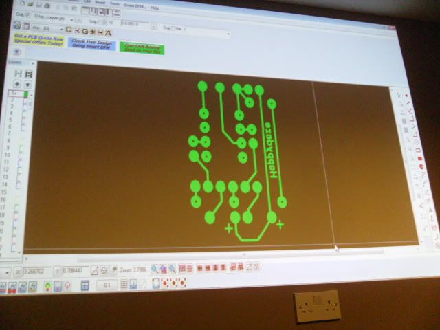
    PCB layout designed in free pcb, then loaded into viewmate
    PICT0251.jpg

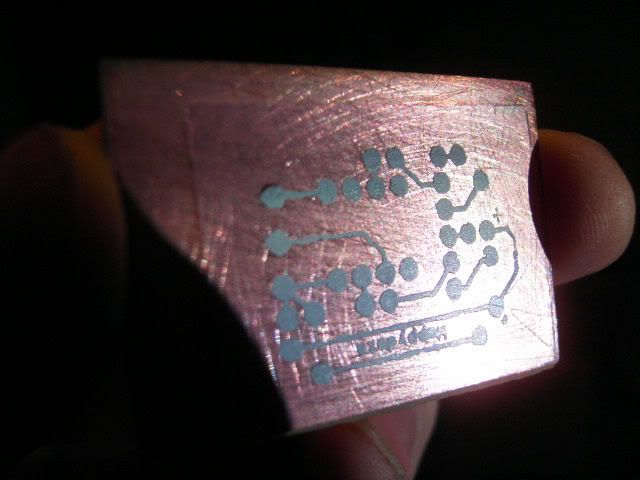
    Printed with a laser printer onto photo paper, then iron onto copper clad board. Toner is etch resistant.
    PICT0256.jpg

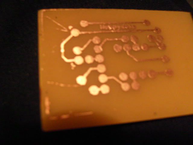
    Etched in ferric chloride solution to disolve the exposed copper, then clean off the toner, and ready to be drilled for components.
    PICT0260.jpg

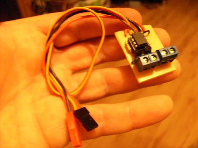
    Finished board, with receiver cable, power for led`s, and connectors to connect led`s into. Two connectors for 2 outputs from chip, through 2 transistors, one output is progrmammed for a flashing sequence, the other for always on. These can be changed by connecting the chip to the PC and changing the programming.
    PICT0263.jpg


Comments

  • Closed Accounts Posts: 13,422 ✭✭✭✭Bruthal


    Here it is working, i set the pic chip programming to do 1 flash, a pause, then 2 quick flashes, as can be seen, and also the other set of lights just stays on, during the time the radio channel is switched on.


    Anyway, as i say, too much time on my hands lately.


  • Closed Accounts Posts: 3,399 ✭✭✭Kashkai


    Robbie,

    You're an electrical artist:).

    You might have found a nice little sideline there. How much would it cost you to make one of those circuit boards, if you were to sell them, hint, hint;)


  • Closed Accounts Posts: 13,422 ✭✭✭✭Bruthal


    It wouldnt be expensive anyway, probably €5 or so to make, less for a single output one, but there is a bit of work in making them, although the first one is the hardest, writing the program, and designing the PCB take a while, but they are done now at least.

    Getting the program to sense the receiver pulse width`s was the fun bit.

    I could even add a line into the program that starts lights flashing after a half hour from switch on, to tell you your flying that long. Or 7 minutes on a heli for example.

    Its all down to what we can think of getting it to do, using a spare channel.


Advertisement