Advertisement
Help Keep Boards Alive. Support us by going ad free today. See here: https://subscriptions.boards.ie/.
If we do not hit our goal we will be forced to close the site.
Current status: https://keepboardsalive.com/
Annual subs are best for most impact. If you are still undecided on going Ad Free - you can also donate using the Paypal Donate option. All contribution helps. Thank you.
If we do not hit our goal we will be forced to close the site.
Current status: https://keepboardsalive.com/
Annual subs are best for most impact. If you are still undecided on going Ad Free - you can also donate using the Paypal Donate option. All contribution helps. Thank you.
https://www.boards.ie/group/1878-subscribers-forum
Private Group for paid up members of Boards.ie. Join the club.
Private Group for paid up members of Boards.ie. Join the club.
Hi all, please see this major site announcement: https://www.boards.ie/discussion/2058427594/boards-ie-2026
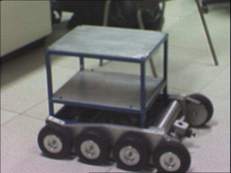
[Robot] Dagda
-
12-07-2011 11:40AM#1

Comments

Advertisement