Advertisement
If you have a new account but are having problems posting or verifying your account, please email us on hello@boards.ie for help. Thanks :)
Hello all! Please ensure that you are posting a new thread or question in the appropriate forum. The Feedback forum is overwhelmed with questions that are having to be moved elsewhere. If you need help to verify your account contact hello@boards.ie
Hi there,
There is an issue with role permissions that is being worked on at the moment.
If you are having trouble with access or permissions on regional forums please post here to get access: https://www.boards.ie/discussion/2058365403/you-do-not-have-permission-for-that#latest

DIY Circuits

  • 21-10-2010 3:46pm
    #1
    Closed Accounts Posts: 6


    Hey Guys

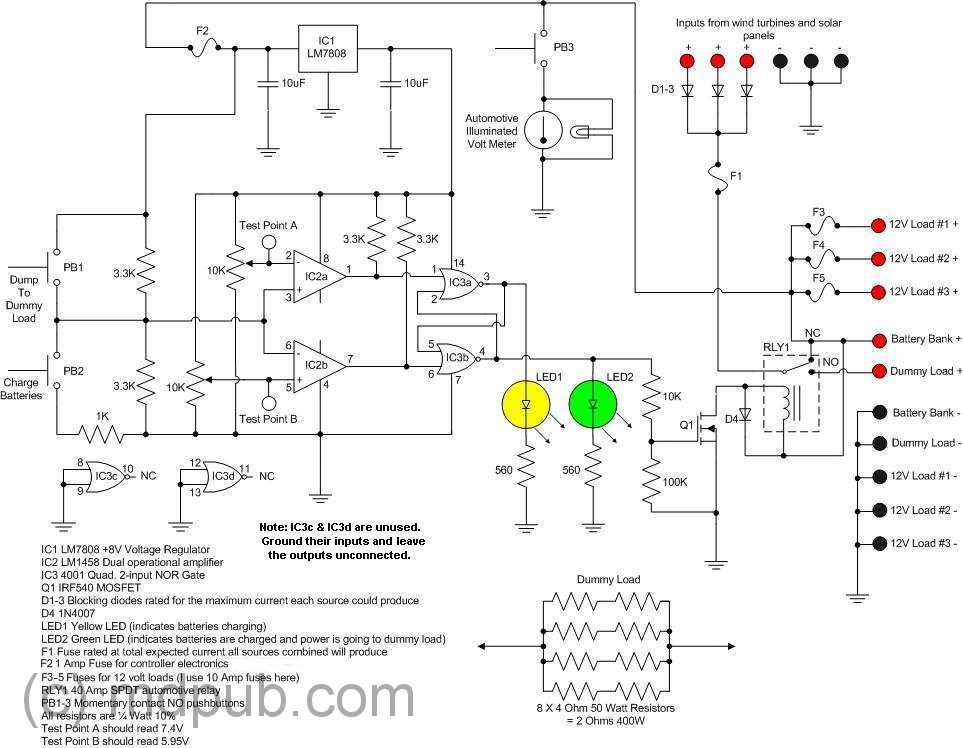
    Im a CivEng grad and interested in buiding (very small) a wind turbine as a project.

    Part of it requires a charge controller. I was wondring how difficult it would be to build the following and or how much it would cost to get it custom built.

    John

    chargecontrollerschematic.jpg


Comments

  • Registered Users, Registered Users 2 Posts: 3,862 ✭✭✭mikhail


    The components are relatively cheap - tens of euro plus whatever the batteries come to, I'd estimate (though I'm not sure about that volt meter). The real cost would be labour. I don't know what's typical, but I'd recommend getting a few quotes as it'll likely vary a good bit.


  • Registered Users, Registered Users 2 Posts: 1,807 ✭✭✭Poly


    you could build it on a breadboard or vero board fairly cheaply, maplin or radionics should have all the bits.

    Instead of the volmeter, you could just use your multimeter and save a few bob


  • Closed Accounts Posts: 6 heresjohnny


    Thanks guys,

    Have to admit im pretty much a complete noob to all this.

    This maybe a stupid question but I guess i
    -Get the board
    -Get the components
    -Solder the connections?

    John


  • Registered Users, Registered Users 2 Posts: 2,945 ✭✭✭D-Generate


    If you use breadboard then there is no need to solder. It is also much easier if it is your first time building a circuit as will teach you how to lay out circuits in an organised fashion.

    I suggest getting a breadboard, testing your circuit on that to make sure it works and then transfer it to Veroboard if it all works out. Veroboard is pretty cheap but breadboards cost a bit more but are reusable.


  • Registered Users, Registered Users 2 Posts: 3,862 ✭✭✭mikhail


    Yeah, breadboard makes circuit-building a bit like the big flat board you'd get in a lego set as a kid - you clip all the pieces into it to make your circuit, and if something's wrong, you can pull it out and start again. It's for prototyping.

    Stripboard (or veroboard as D-Generate called it) is what you transfer the final circuit onto and then solder.

    A quick google search should give you a decent idea what I mean.


  • Advertisement
  • Registered Users, Registered Users 2 Posts: 1,807 ✭✭✭Poly


    Hey Johnny. Do you have a discription of the circuit? What's the purpose of the dummy load?


  • Registered Users, Registered Users 2 Posts: 5,401 ✭✭✭DublinDilbert


    Dummy load is to dump the power being generated as the batteries are fully charged.

    Dummy load could be a heater and warm up water...


  • Registered Users, Registered Users 2 Posts: 1,134 ✭✭✭FarmerGreen


    Did anyone else spot the mistake in the circuit diagram?
    Hint-what happens when you push PB1?


  • Registered Users, Registered Users 2 Posts: 1,807 ✭✭✭Poly


    Did anyone else spot the mistake in the circuit diagram?
    Hint-what happens when you push PB1?

    burn the sh1te out of IC2?


Advertisement