Advertisement
If you have a new account but are having problems posting or verifying your account, please email us on hello@boards.ie for help. Thanks :)
Hello all! Please ensure that you are posting a new thread or question in the appropriate forum. The Feedback forum is overwhelmed with questions that are having to be moved elsewhere. If you need help to verify your account contact hello@boards.ie
Hi there,
There is an issue with role permissions that is being worked on at the moment.
If you are having trouble with access or permissions on regional forums please post here to get access: https://www.boards.ie/discussion/2058365403/you-do-not-have-permission-for-that#latest

Adapter Cable

  • 30-11-2009 3:36pm
    #1
    Registered Users, Registered Users 2 Posts: 1,596 ✭✭✭


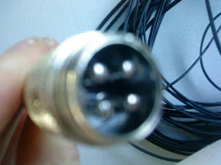
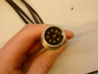
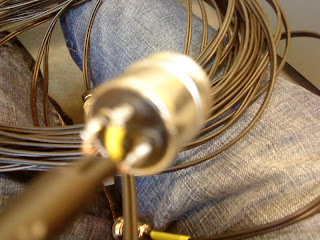
    I am looking for a cable which will allow me to connect this connection:

    image-upload-163-744963.jpg

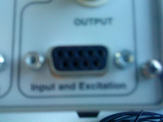
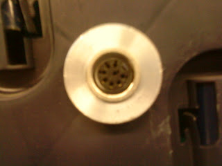
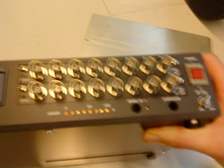
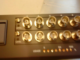
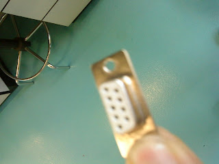
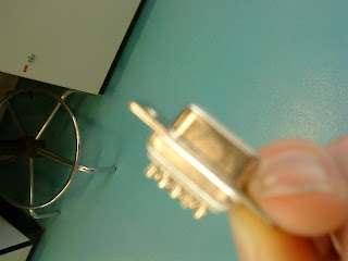
    to this input:

    image-upload-166-710884.jpg

    I was in PEATS and they had never seen the connection before.

    (Apologies about the image quality)


Comments

  • Registered Users, Registered Users 2 Posts: 5,401 ✭✭✭DublinDilbert


    Do you know if the two devices are electrically the same? so its just a mater of making a physical connection, or does it need some sort of conversion?

    I could be wrong, but i doubt you'll find an adapter, unless its a fairly common problem, so you'd probably need to make something up.


  • Registered Users, Registered Users 2 Posts: 1,596 ✭✭✭AIR-AUSSIE


    Do you know if the two devices are electrically the same? so its just a mater of making a physical connection, or does it need some sort of conversion?

    I could be wrong, but i doubt you'll find an adapter, unless its a fairly common problem, so you'd probably need to make something up.

    Electronics is far from my field of expertise really so you will have to bare with me. I would imagine I would have to build it too, but where could I find the stuff I would need?

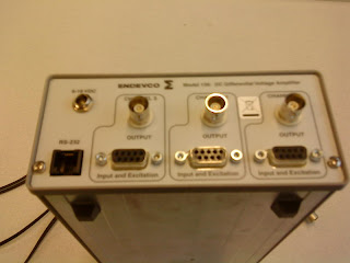
    I will be doing an experiment using this equipment. I am connecting accelerometers to an amplifier. The accelerometer has a female connection of the connection shown in the first picture. I have a cable which I can connect to this and the other end of this cable is the connection shown in the first picture. The back of the amplifier is shown in the second picture.

    What do you mean by electrically the same? Or how would I find out. The cable would be carrying data from the accelerometer to the amplifier, I guess if the cable is carrying the data in a different type to the way the amplifier needs it, I would need a adapter.

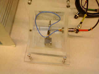
    Here is a lay out of the equipment attached, just to confirm the arrangement I have.


  • Closed Accounts Posts: 3,293 ✭✭✭Fuzzy Clam


    Air-Aussie, I used to wire up similar types of equipment years ago. Unless the equip supplier can supply you with the correct cable, you will have to assemble it yourself, or get it done for you.

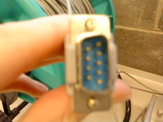
    www.radionics.ie have a range of multipole connectors similar to the one in the top pic. If they don't have a 4 pole one, it may be nessesary to get one that takes 8 pins instead of 4, and just use the 4 required. The bottom pic is of a standard 9 pin "D" connector.
    You will need to know the TX, RX and ground pins on the multipole.

    You will need to know exactly what your looking for before ordering from Radionics as they won't go thru the stock to find a match.

    If you're unsure of what you're doing, pm me and I may be able to give you the address of a company that might help you.

    Of course, I'm assuming that you can make a straight forward connection between the 2 equipment.

    A simpler option may be to cut off the top connector and wire in a male "D" connector.


  • Registered Users, Registered Users 2 Posts: 5,401 ✭✭✭DublinDilbert


    Fuzzy Clam wrote: »
    You will need to know the TX, RX and ground pins on the multipole.

    Just cause its a 9pin d type connector, it doesn't mean its a serial port or carries any digital data. It could be almost any type of signal.


    AIR-AUSSIE wrote: »
    What do you mean by electrically the same? Or how would I find out. The cable would be carrying data from the accelerometer to the amplifier, I guess if the cable is carrying the data in a different type to the way the amplifier needs it, I would need a adapter.

    Here is a lay out of the equipment attached, just to confirm the arrangement I have.

    When i say electrically the same, i mean are they compatible? It sounds like they are, as they are both analogue signals.

    You need to read up the datasheet for the accelerometer and make sure that its max output voltage is not going to exceed the max input of the amplifier.

    Then you'll need to find the pin-out data for your cable and the input to the amplifier. If you post that data we'll be able to advise on how to construct an adapter.


  • Registered Users, Registered Users 2 Posts: 1,596 ✭✭✭AIR-AUSSIE


    Right it seems what I need in terms of cables has changed... But the cable I now need may be easier to get.

    As far as whether or not I need an actual adapter I haven't checked properly yet, but by the way my supervisor is talking I would imagine I won't. BUT I will check this out properly.

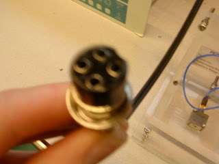
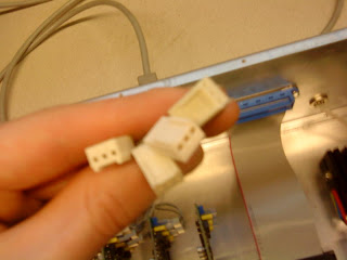
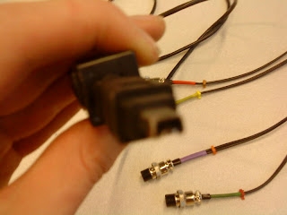
    Right this will take a while to explain. But at the moment is four accelerometers are attached into one cable which has a d-pin connection at the end I can then attach this to a connection which seperates this cable back into four cables. These cables have the connection below. I need this connection to be changed back to a d-pin connection so it can be connected to the amplifier.

    image-upload-23-700382.jpg
    Sorry again for the bad image all I have is my phone to take photos.

    Thanks for your help.


  • Advertisement
  • Registered Users, Registered Users 2 Posts: 5,401 ✭✭✭DublinDilbert


    AIR-AUSSIE wrote: »
    Right it seems what I need in terms of cables has changed... But the cable I now need may be easier to get.

    As far as whether or not I need an actual adapter I haven't checked properly yet, but by the way my supervisor is talking I would imagine I won't. BUT I will check this out properly.

    Right this will take a while to explain. But at the moment is four accelerometers are attached into one cable which has a d-pin connection at the end I can then attach this to a connection which seperates this cable back into four cables. These cables have the connection below. I need this connection to be changed back to a d-pin connection so it can be connected to the amplifier.

    image-upload-23-700382.jpg
    Sorry again for the bad image all I have is my phone to take photos.

    Thanks for your help.

    You'll need to provide pin out information for the devices your trying to connect, before anyone will be able to help.

    Also if you could draw up a basic schematic, that would be good also.


  • Registered Users, Registered Users 2 Posts: 1,596 ✭✭✭AIR-AUSSIE


    Right here is a few photos showing the arrangement of equipment.

    1 Accelerometer
    image-upload-13-777850.jpg

    2 Cable Connection to Accelerometer
    image-upload-17-771410.jpg

    Cable between Accelerometers (4) to extension lead
    image-upload-23-746611.jpg

    3 End Connection of cable to extension lead
    image-upload-26-742845.jpg

    4 Connection on extension lead
    image-upload-32-767441.jpg
    image-upload-21-784389.jpg

    5 End Connection from extension lead
    image-upload-26-704628.jpg

    6 Split above connection into four seperate channels (as three accelerometers will be attached only 3 cables will be used)
    image-upload-23-720657.jpg

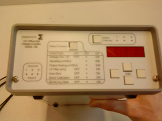
    7 Front of Amplifier
    image-upload-25-774507.jpg

    8 Back of Amplifier
    image-upload-26-793921.jpg

    The three channels need to be connected into the Amplifier into the three d pins. The output from the amplifier will be from the circular connections on the back of the amplifier (photos above). THis will then be connected to the recorder as shown below.

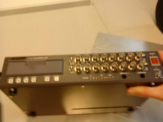
    9 Recorder
    image-upload-20-707514.jpg
    image-upload-17-729653.jpg
    image-upload-20-748438.jpg

    The Recorder will then be attached to a laptop using the connection below.

    10 Connection from recorder to laptop
    image-upload-25-735262.jpg
    image-upload-30-766037.jpg

    Data sheet for Model 136 DC Amplifier is attached below.

    Link to Accelerometer Data Sheet

    Information on Recorder
    TEAC LX 10 Recording Unit (1)

    TEAC LX 10 Recording unit (2)

    Also just so you know, I did not build the current arrangement I have, I took it over from someone else and we have also bought a new amplifier so this is why I need to adapt the configuration of the cables. Also I have pretty much no electrical experience so if something looks wrong it probably is and I'd appreciate if you'd point any shortcoming the current system may have as it may significantly reduce the problems I have in the future with it.

    Thank you for your help.

    I will also attach a schematic later today.


  • Registered Users, Registered Users 2 Posts: 1,596 ✭✭✭AIR-AUSSIE


    Please find attached a schematic of the equipment I'm trying to set up.

    The numbers in the black circles coincide with the numbering of the images above in my previous post.


  • Registered Users, Registered Users 2 Posts: 5,401 ✭✭✭DublinDilbert


    AIR-AUSSIE wrote: »

    image-upload-23-700382.jpg

    Can you confirm how many wires are going into the back of the "molex" style plug shown above? I would guess its 3 as based on the accelerometer datasheet, but do confirm.

    Ok, So basically you need a three cables, to connect the "molex" style plug shown above to three 9 pin D connectors on the amplifier.

    Based on my reading of the accelerometer datasheet I see that the accelerometers need to be powered, as each has a power, ground, signal pin. But after the extension lead they go into a 9 pin connector which I would guess means they must be sharing some of the power pins.

    Your going to need someone with electrical/electronic experience to help set this up.


  • Registered Users, Registered Users 2 Posts: 5,401 ✭✭✭DublinDilbert


    What i would advise would be to ditch all of the cables / extension leads for now and try set up one accelerometer onto one channel of the amplifier and get that to work first. Then measure the voltage output from the BNC connector with a multimeter.

    I've attached a basic schematic of how i think one should be wired up.


  • Advertisement
  • Registered Users, Registered Users 2 Posts: 1,596 ✭✭✭AIR-AUSSIE


    What i would advise would be to ditch all of the cables / extension leads for now and try set up one accelerometer onto one channel of the amplifier and get that to work first. Then measure the voltage output from the BNC connector with a multimeter.

    I've attached a basic schematic of how i think one should be wired up.

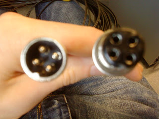
    Right Ok, I took apart one end of the cable shown below that connects to the accelerometer setup. The connection on the right is the end that connects to the accelerometer.

    So if I cut the wires on the back as shown in the 2nd photo and attach it to a d pin as shown in the third picture attaching the cables to the numbered connection on the d pin I can then use this to attach one accelerometer to the amplifier?

    image-upload-48-794308.jpg

    image-upload-54-703728.jpg

    image-upload-51-744662.jpg

    image-upload-48-721963.jpg

    I assume my lab will have a multimeter somewhere? So I will need a cable with this connection end to connect the amplifier to the multimeter?

    BNC_connector.jpg&h=78&w=83&usg=__dyLDSCLTZ7-TOvGC4OAR3Efia78=


  • Registered Users, Registered Users 2 Posts: 5,401 ✭✭✭DublinDilbert


    AIR-AUSSIE wrote: »
    I can then use this to attach one accelerometer to the amplifier?
    Yep that should work, once you figure out correct pinout ;)
    AIR-AUSSIE wrote: »
    I assume my lab will have a multimeter somewhere?
    I'm not really sure what "your" lab has, but it wouldn't be unusual to find one in a lab.


    AIR-AUSSIE wrote: »
    So I will need a cable with this connection end to connect the amplifier to the multimeter?
    Yea you could use a cable, but must peope would just get an assistant to hold the probes onto the BNC connector, while they shake the accelerometer to see if its working.


  • Registered Users, Registered Users 2 Posts: 1,596 ✭✭✭AIR-AUSSIE


    Yep that should work, once you figure out correct pinout ;)


    I'm not really sure what "your" lab has, but it wouldn't be unusual to find one in a lab.


    Yea you could use a cable, but must peope would just get an assistant to hold the probes onto the BNC connector, while they shake the accelerometer to see if its working.

    Grand I'll try and sort out soldering the wires to the d-pin connection.


  • Registered Users, Registered Users 2 Posts: 1,596 ✭✭✭AIR-AUSSIE


    DublinDilbert

    In your schematic that you attached the 'green' wire is divided between the 8 and 4 pin of the 9pin d connection. How would i do this? DO I just separate the copper wires evenly between the two?


  • Registered Users, Registered Users 2 Posts: 5,401 ✭✭✭DublinDilbert


    AIR-AUSSIE wrote: »
    DublinDilbert

    In your schematic that you attached the 'green' wire is divided between the 8 and 4 pin of the 9pin d connection. How would i do this? DO I just separate the copper wires evenly between the two?

    Use a small off cut of wire to create a jumper. ;)

    I'm not being smart, but it would best if there was a lab-tech or another student around to check your work / schematic before you plug anything in and damage any equipment.


  • Registered Users, Registered Users 2 Posts: 1,596 ✭✭✭AIR-AUSSIE


    Use a small off cut of wire to create a jumper. ;)

    I'm not being smart, but it would best if there was a lab-tech or another student around to check your work / schematic before you plug anything in and damage any equipment.

    DublinDilbert

    I have made up the wire. Well I tried but the soldering iron wasn't very good and the chisel was too big. So I got All Cables Inc to make it up. I'm going to try it now so hopefully it will work.


Advertisement