Advertisement
If you have a new account but are having problems posting or verifying your account, please email us on hello@boards.ie for help. Thanks :)
Hello all! Please ensure that you are posting a new thread or question in the appropriate forum. The Feedback forum is overwhelmed with questions that are having to be moved elsewhere. If you need help to verify your account contact hello@boards.ie
Hi there,
There is an issue with role permissions that is being worked on at the moment.
If you are having trouble with access or permissions on regional forums please post here to get access: https://www.boards.ie/discussion/2058365403/you-do-not-have-permission-for-that#latest

Solar Install; the on-going saga

2456710

Comments

  • Posts: 5,238 ✭✭✭ [Deleted User]


    My alternator charge to the leisure batteries is feeble. It'll just about run the fridge producing about 10 amps max. with a voltage drop of ~0.4v idle & ~0.8v laden.
    However it's a 65ah alternator.
    I've been tinkering, swapping the regulator gave me an increase in volts but not amps.

    I was having notions of installing a zero centre ammeter in the dash to monitor affairs. Shortfall/generation.
    [EDIT: Shortfall = battery discharge with engine running or starter battery charging with engine off and solar generating while battery link switch is closed]


    img_52_ampere_s_192xx_en,property=original.jpg

    oooh shiney! :)

    The TM tells me when I run the fridge, auto-electrics, wipers, 220watts of dipped lights (yes I could just clean the old lenses but it was easier to install aux. lights) that I'm running at discharge. I believe this to be a shunt bypass related anomaly because my clamp meter says it's all good.

    I've gone off the idea now as if I just remedy the problem then I won't have to monitor and compensate.

    Back when I was initially installing my leisure battery alternator charge do-fer, I hadn't a clue how to wire a relay so I just butchered a few sets of 400 < 200 amp jump leads and wired direct from the starter +ive to dash switch back to leisure battery +ive & common ground.
    This has grown to be a 6 - 8 meter round trip with an assortment of (double fused) cowboy connections.
    Now add another 1.5m to install an internally shunted ammeter and you see where this is going.

    [EDIT: in defense of VDO pictured, that's a proper externally-remote shunted ammeter,...I was looking at cheap and cheerful versions]

    400 amp jump leads are not the same thing at all as 400amp cable. If anything there's a decent amount of copper in them and 400amp insulation for instantaneous loads. The stranded cores themselves are only about 4mm-6mmØ which is actually 70-100amp continuous, and ferociously expensive.

    Bare in mind cable ratings are for max allowable temperature not min. allowable voltage drop.
    Eg. 10 amp cable = 1.5mmØ
    Cable required to carry 10A @ 12VDC 10meters with less than 3% voltage drop = 4mmØ
    This is why electrical wholesalers think I'm mental :D.
    A point worth noting in regard to this is that inline fuses are more often than not on unsuitable cable.


    So I dug out some real 125 amp cable on a 1m run between batterys and load tested the circuit. I decided the alternator was in fine working order and it was time to stop before I melted something with heavy loading at idle at ~+30 amps.

    I couldn't be bothered stripping out most of the old cable so I'm putting a 30A relay in, with the jump leads as the signal live.

    Another problem with my current set up is the classic; solar voltage is confusing main charger chestnut.

    If I run the fridge on 12volt with the alternator, on a cloudy day with the solar on I hit shortfall; batteries are discharging with engine running. Solar isn't giving me any significant amps, just volts which is telling the alternator regulator to reduce electron production. facepalm.gif

    In defense of my soon to be decommissioned alternator charge link, the cable is so long it's acting as a natural resistor preserving my sealed batteries from overcharge, how and ever there are better ways to proceed.


  • Posts: 5,238 ✭✭✭ [Deleted User]


    I've been emailing [EMAIL="support@morningstarcorp.com...love"]support@morningstarcorp.com [/EMAIL] ...love their customer service :)

    I sent them this and some questions.
    TriStar PWM Regulation.jpg

    This is a simplified wiring diagram for clarity. Relay detail and fuses are not indicated.

    What I wanted to know was; can I wire my alternator into the TriStar-45 with a schottky diode (low voltage drop) to protect my starter battery from unregulated solar charge and regulate my alternator output down to 14.4v PWM for the leisure batteries.

    They replied as long as I don't exceed the rated 45amp load tolerance for the TriStar then this will work and is suitable.
    extra_happy.gif
    I can prevent overloading the TriStar by not overloading it and by using a 30amp fuse on the alternator side and a 10 amp MCB on the solar side. Ooh poo, I just realised I may need a new DC circuit breaker for the output, feck, I'm only after putting in an order!

    Having one final regulator will also solve the solar regulator versus alternator regulator voltage crisis.


    eh...might as well maxi-blade fuse the inverter too while I'm at it. :o


  • Posts: 5,238 ✭✭✭ [Deleted User]


    I've also been belligering Elecsol to publish their charge parameters. No reply.
    The website is down.
    I suspect old Steve may be going down with his ship.
    I found this thread quite amusing regarding Elecsol Corp.


  • Closed Accounts Posts: 1,927 ✭✭✭paddyp


    Most jump leads are a joke, welding cable from the local co-op is a reasonable way to get chunky copper.

    That elecsol thread is great craic, "The latest Annual Accounts submitted to Companies House for the year up to 30/06/2012 reported 'cash at bank' of £100, 'liabilities' worth £0, 'net worth' of £100 and 'assets' worth £100."

    It must be hard to sleep with all that cash under the mattress.

    Elecsol batteries:


  • Posts: 5,238 ✭✭✭ [Deleted User]


    Welding cable only comes in single core though. Harder to keep neat although highly noteworthy.

    http://www.demesne.ie/cablecablecleats.html
    http://www.jdcables.com/index.php

    For super-serious inexpensive cable Hugh Piggott recommends making it by filling a copper pipe with strands gleaned from cheaper 3 core. I wonder how he insulates it though.

    I bet Steve goes online under pseudonames as the voice in the wilderness declaring he got his warranty honoured.


  • Posts: 5,238 ✭✭✭ [Deleted User]


    I wonder how he insulates it though.

    He doesn't elaborate much more than this.
    DIY armoured cable.jpg


  • Closed Accounts Posts: 1,927 ✭✭✭paddyp


    He doesn't elaborate much more than this.
    DIY armoured cable.jpg

    He's talking about using copper pipe as butt crimp or sleeve crimp. I've used that myself to make lug terminals and buttjoints for but I'd always fill the joint with solder.

    re; welding cable You generally only need single core in a vehicle though as the chassis is ground. I've used 6mm twin core van damme speaker cable in places as I had a roll of it -189 conductors 3.2 ohms per km. You can hardly cut the insulation with a stanley


  • Closed Accounts Posts: 1,927 ✭✭✭paddyp


    paddyp wrote: »
    He's talking about using copper pipe as butt crimp or sleeve crimp. I've used that myself to make lug terminals and buttjoints for but I'd always fill the joint with solder.

    re; welding cable You generally only need single core in a vehicle though as the chassis is ground. I've used 6mm twin core van damme speaker cable in places as I had a roll of it -189 conductors 3.2 ohms per km. You can hardly cut the insulation with a stanley

    Are you thinking of doing a piggot turbine? I looked into it before I recon you'd want to be making at least a 2kw version to make it worthwhile as even in windy areas like mine you'll average 1/3 of that , I did find a free souce of neodynium magnes though at the council tip lately - magnetic resitance excercise gear rowers etc have enough for about 1/4 - 1/3 of a rotor, if you live somewhere populous you could probably picke up enough of them for free between gumtree, adverts, munster free ads, buyandsell, donedeal etc.


  • Posts: 5,238 ✭✭✭ [Deleted User]


    paddyp wrote: »
    re; welding cable You generally only need single core in a vehicle though as the chassis is ground.

    facepalm.gif
    I always amaze myself how I can overlook the obvious. Now that you mention it there's probably close to 100m of superfluous cable in here. AC habits die hard.
    paddyp wrote: »
    Are you thinking of doing a piggot turbine? I looked into it before I recon you'd want to be making at least a 2kw version to make it worthwhile as even in windy areas like mine you'll average 1/3 of that , I did find a free souce of neodynium magnets though at the council tip lately - magnetic resitance excercise gear rowers etc have enough for about 1/4 - 1/3 of a rotor, if you live somewhere populous you could probably pick up enough of them for free between gumtree, adverts, munster free ads, buyandsell, donedeal etc.

    Yeah I reckon at least a 3kw, I've an anemometer up on one site about 6 month's and it's not looking too hopeful. I'm hoping eventually to build an off-grid workshop and expand from there if that's feasible.
    I won't be erecting one unless I can find a site averaging 7m/s @ 9m (You don't need planning permission for a hub <10m once you have no structures within that horizontal radius IIRC).
    I could be anywhere between the midlands, Dublin and the UK these days. It's unlikely I'll have anytime for new projects between here and January though. Old projects are still looking at me all sad eyed and neglected.
    I'm still on the lookout for a smart drive washing machine motor to tinker with.


  • Advertisement
  • Closed Accounts Posts: 1,927 ✭✭✭paddyp


    facepalm.gif
    I always amaze myself how I can overlook the obvious. Now that you mention it there's probably close to 100m of superfluous cable in here. AC habits die hard.


    Yeah I reckon at least a 3kw, I've an anemometer up on one site about 6 month's and it's not looking too hopeful. I'm hoping eventually to build an off-grid workshop and expand from there if that's feasible.
    I won't be erecting one unless I can find a site averaging 7m/s @ 9m (You don't need planning permission for a hub <10m once you have no structures within that horizontal radius IIRC).
    I could be anywhere between the midlands, Dublin and the UK these days. It's unlikely I'll have anytime for new projects between here and January though. Old projects are still looking at me all sad eyed and neglected.
    I'm still on the lookout for a smart drive washing machine motor to tinker with.

    When you factor in battery banks you'd need at least 3kw alright. Neighbour averages 7.5m/s but its often maxxed out around here so his average power is better than the average windspeed would indicate. He has grid tie so no battery bank shenannigans and wound the meter back a month in the first week, first few thousand units are subsidised too so it takes a bit of the initial pain away.


  • Posts: 5,238 ✭✭✭ [Deleted User]


    I'm thinking of going down the 48v road. I'd be more inclined to put the investment in a hydro rig if I can get the right site, but considering the fickle nature of renewables 'tis best have as many sources as possible. Battery shenanigans! Hahaha, bring it! :D.

    Off-grid really doesn't really make a lot of cents apart from the challenge unless you are very remote, it usually costs more to cycle a battery than grid charges, coupled with lack of generation when batteries are full and replacing the batteries every 7ish years it's not viable for most.

    I'd probably consider grid-tie further down the line, when I'm in the mood to have certifiable equipment.

    Those free inverters are all gone now, and the feed-in tariffs have dropped to less than half what they were in good 'ole near-sighted Éire. I'll more than likely be moving to the UK for this, they've far superior schemes.


  • Posts: 5,238 ✭✭✭ [Deleted User]


    paddyp wrote: »
    Neighbour averages 7.5m/s but its often maxxed out around here so his average power is better than the average windspeed would indicate. .

    It'd be worth looking into using immersion or water tank heaters as the dump loads if production is that good.


  • Posts: 5,238 ✭✭✭ [Deleted User]


    Finally got a chance to work some more on the system. Feckin' work is always ruining my life.

    I've some fresh new impressive numbers.

    Temperature 14°C
    Batteries fully charged and idled 20 hours

    Battery #1
    Battery Voltage 12.9v


    __________Specific Gravity_____S.G. @ 20°C_____Voltage
    ____________(± 0.010)______________________________
    Cell #1________1.215____________1.214___________2.2v
    Cell #2________1.235____________1.234___________2.1v
    Cell #3________1.235____________1.234___________2.2v
    Cell #4________1.215____________1.214___________2.2v
    Cell #5________1.230____________1.229___________2.0v
    Cell #6________1.215____________1.214___________2.2v

    S/G at new 1.250 per cell

    Average Cell S.G. = 1.223
    16% DOD

    84% of 125Ah
    Present Capacity = 105Ah

    Battery #2
    Battery Voltage 13.1v


    __________Specific Gravity_____S.G. @ 20°C_____Voltage
    ____________(± 0.010)______________________________
    Cell #1________1.225____________1.224___________2.5v
    Cell #2________1.235____________1.234___________2.2v
    Cell #3________1.230____________1.229___________2.2v
    Cell #4________1.235____________1.234___________2.2v
    Cell #5________1.230____________1.229___________2.2v
    Cell #6________1.230____________1.229___________2.0v


    Average Cell S.G. = 1.230
    11% DOD

    89% of 125Ah
    Present Capacity = 111Ah

    New Bank Total = 216Ah
    28.5Ah recovered

    Agenda #1: does PWM recover lost capacity

    Yes

    Agenda #2: Can Elecsol Batteries be left depleted and not get damaged as the manufacturers claim

    Hard to argue with those numbers....yeah why not! Although I still reckon they're soft shorting.....maybe I'm using more electrons than I used to because I know where to find more now.

    Given that the weakest battery is now the strongest I swapped them around so Battery #1 is closest the solar controller now.


  • Posts: 5,238 ✭✭✭ [Deleted User]


    Alternator charge circuit is now re-wired as per post #53 with minor modifications.

    New additions to the family.JPG

    I used a double schottky diode mounted on it's own heak sink for the circuit. One side protects the starter battery from unregulated solar charge. The other is to protect the Tristar's lightning protective devices from the overwhelming inductive potency of my mighty fridge fans giggle.gif.

    See page 37, fig 5.3 here. for the hows and whys.

    I tested the circuit with my cheapo Halfords charger which made it's glorious and spectacular exit of this world with a bang and a puff of that magic smoke.
    Normally I'd charge the batteries as per bank but I was trying to get the charger to simulate the alternator and it did for five minutes then I think it lost a fight with the Tristar.
    I second guessed myself about a few things I could have done wrong and re-wired them wronger then fixed it properly and realised that was how I had it the first time, and twas a sh1te charger anyways so no matter. It's in the bone yard now.

    However the alternator is working just fine in the new arrangement. It compensates for loading within -300mA, tested up to 14amps with fully charged batteries and isolated from solar.

    There's 0.4v drop on the relay activated battery link and diode which is no big deal because the solar module can boost this to the required 14.4v with no stress due to the additional current and besides when my starter is fully charged 14.8v - 0.4v = 14.4v :).
    I went out of my way to get a fused relay for this to reduce the amount of fuse holders I have everywhere, now I realise in the new set-up this is already protected by a maxi-blade and circuit breaker so all it's doing is adding resistance, I'll be swapping that first opportunity. I'm still debating if a larger relay is better because it's more conductive or worse because it requires a stronger electromagnet.

    So...I'm currently in the market for a good cheap 20A, 25A or 30Ax3 bank mains charger...still debating if I want to spring for a Sterling Power ProCharge U. Any recommendations are welcome.


  • Posts: 5,238 ✭✭✭ [Deleted User]


    paddyp wrote: »
    re; welding cable You generally only need single core in a vehicle though as the chassis is ground.

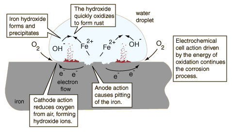
    I found an argument against this method which if anyone else asks I'm going to pretend I planned all along....

    Galvanic corrosion whistling.gif.


    corrosion.gif


  • Advertisement
  • Posts: 5,238 ✭✭✭ [Deleted User]


    I had another epiphany this morning.
    I was trying to convince myself I needed one of these. To replace my mains charger.

    40%20amp%20front%20VERYSMALL.jpg

    I'm finding it very difficult to justify the cost for 5 reasons.
    A: my car cost less
    B: I'm only going to use it 12-20 times a year.
    C: Apart from offending my standards, any cheap charger will do because the solar can finish the job correctly after the mains charger is done.
    D: This is a state of the art 30A mains charger for £300+, I can get the same functionality from a 45A solar controller for £120 (turns out now is the time to buy solar equipment...everything is on sale in the Winter). £120 in mains charger world won't get you much worth noting as far as I can tell.
    E: There seems to be some issue with both Sterling and Pronautic chargers as the input voltage sensing relays are frequent to give up...although any reports of this I've seen are promptly followed by both companies' excellent after-service and unit replacement.

    So eureka, I don't need a separate mains charger. I need a brutish 20A 24v transformer. :D
    According to the manual the TS can take up to a 48v input.
    $T2eC16ZHJIMFHJ!tutLsBSYLlDDNdQ~~60_12.JPG

    Time to email Morningstar again. :D
    TriStar as Mains Charger.JPG

    Details on wiring diagram;

    Because of recent installation of a diode between the starter battery and solar module and rerouting of charge I've lost the ability to charge my starter off the solar module, that's why the switched +ive is being added.
    The changeover relay is to prevent +24vDC heading into the solar module and I think a better solution than a diode because I don't want any voltage drop from the solar module.


  • Posts: 5,238 ✭✭✭ [Deleted User]


    D'oh facepalm.gif

    It just dawned on me; I only want 20A ~ 25A @14V, not 20A @24V so I only need a 350 watt traffo...Wa-hey even cheaper :cool:.


  • Posts: 5,238 ✭✭✭ [Deleted User]


    It'll be a while before I get this tackled. But thanks to drawing this out I realised I ordered the wrong thermostatic switch. It'll be Normally Open I'll be needing then (open until 50°C then closed thereafter). :o

    I'll spare yee another page of mathematical formulae and sums.
    A: I bet nobody'll read them :p and B: chances are I got something wrong anyways. ...what can I say I'm a cut twice measure once kinda guy. If the components work as they should under a bench test then it's a go-er. I'll take a multimeter over a calculator any day.

    Suffice to say I've hopefully re-calculated correctly the minimum required resistance for this circuit with new fan specs. to keep the fans operating within their voltage tolerances with linear variable speed control via a potentiometer giving max to min revs. without stalling (noise control), and an override-off switch for night-time if this isn't enough. An override-on switch could be added in parallel to the thermostatic switch but I don't see the need (unless I was predicting a thermostatic switch failure...eh i might just use two TS switches in parallel).

    Fridge Fan Circuit Diagram.JPG

    If anyone is thinking of doing similar you could make it a lot simpler by using one of these instead of a resistor and dumping the potentiometer for a simpler on/off setup. I've looked at the efficiencies of a regulator versus a resistor and it's negligible. My only minor concern is that a resistor is neater and cheaper. Not that it'd be difficult to hide a regulator behind the fridge. :rolleyes:

    Using a regulator also opens the market up for any 12v fan, I spent a day trying to source ones that had a wide input range.

    Incidentally the link in post #46 for 6 cheapy fans...complete cowboys! They sent me one fan, then I had to order 3 more and after agreeing they'd cover postage they only sent a partial refund. :mad:


  • Posts: 5,238 ✭✭✭ [Deleted User]


    Life would be so much easier if I only had one type of battery onboard. Really I ought to be open lead acid all the way. In fact now that I know I can pop off my sealed battery caps at will I'm tempted to raise absorption set point to 14.7v and be done with it.
    If I replaced the starter battery for a sealed battery I could also achieve the same but this would be taking a step backwards IMO, even though I could potential save a few bob in the long run and avoid much shenagigans.
    Replacing my sealed leisure bank is not viable while they're on the recovery. ...Unless anyone wants to make me an offer for some previously loved like-new-ish never been abused...ahem...super-bling carbon-fibre amaze-o-pants technology batteries...one previous eldery lady owner????:)

    Meanwhile I came up with this which I may or may not implement depending on whether there's any of those 3.8A battery chargers left in Aldi when I call in next week.

    It's the same circuit as the TS as mains charger with a separate fisher-price charger running to the starter to boost it to 14.7v (I'd almost be willing to bet the temp. compensated TS on a 14.4v set-point would do a better job without it...separate voltage sensing leads make a huge difference) or a CTEK MXS5.
    Still I foresee the need of a back-up charger so it may be interesting how they compare.

    For what it's worth;
    TS45 as Mains Charger with Separate Starter Charger.JPG


  • Closed Accounts Posts: 1,927 ✭✭✭paddyp


    Life would be so much easier if I only had one type of battery onboard. Really I ought to be open lead acid all the way. In fact now that I know I can pop off my sealed battery caps at will I'm tempted to raise absorption set point to 14.7v and be done with it.
    If I replaced the starter battery for a sealed battery I could also achieve the same but this would be taking a step backwards IMO, even though I could potential save a few bob in the long run and avoid much shenagigans.
    Replacing my sealed leisure bank is not viable while they're on the recovery. ...Unless anyone wants to make me an offer for some previously loved like-new-ish never been abused...ahem...super-bling carbon-fibre amaze-o-pants technology batteries...one previous eldery lady owner????:)

    Meanwhile I came up with this which I may or may not implement depending on whether there's any of those 3.8A battery chargers left in Aldi when I call in next week.

    It's the same circuit as the TS as mains charger with a separate fisher-price charger running to the starter to boost it to 14.7v (I'd almost be willing to bet the temp. compensated TS on a 14.4v set-point would do a better job without it...separate voltage sensing leads make a huge difference) or a CTEK MXS5.
    Still I foresee the need of a back-up charger so it may be interesting how they compare.

    For what it's worth;
    TS45 as Mains Charger with Separate Starter Charger.JPG

    If you're ever in cork theres a guy in kibrittain has a pallet load of 6v fork truck batteries never used for about 1/10th of their purchase price. Have one of those aldi chargers, its grand on a new perfect battery but gives up on absoption charge far too soon, and basically doesn't float charge at all so leave a battery connected and it will die.


  • Advertisement
  • Posts: 5,238 ✭✭✭ [Deleted User]


    Cwaor, full-traction? Can you pm me a contact please Paddy, do you know what make/size they are?
    Thanks for the heads up, sounds like the Aldi jobbie is pretty pointless then for my purposes. I may just ramp up to 14.7v all round so. Or do you have any better ideas how to split charge the two banks to separate set-points without spending more than a 75Ah starter battery costs?


  • Posts: 5,238 ✭✭✭ [Deleted User]


    I just received a reply from Morningstar.
    Hello Liam,

    The xfmr output is within spec for the TS-45 controller. We use DC power supplies for in-house testing so this should be fine.

    Regards
    ...
    MS Technical support

    extra_happy.gif


  • Posts: 5,238 ✭✭✭ [Deleted User]


    you could make it a lot simpler by using a regulator and dumping the potentiometer for a simpler on/off setup.

    I found a neat little PWM DC motor speed controller while looking for something else, typically after I've ordered the less ideal thing. This can't be regulated, so it will need a resistor in the circuit and/or fans with wide voltage tolerances...or you could skip the resistor and just remember to never set it above 70% while charging the batteries.

    For those willing to argue over mA whistling.gif


  • Closed Accounts Posts: 1,927 ✭✭✭paddyp


    I found a neat little PWM DC motor speed controller while looking for something else, typically after I've ordered the less ideal thing. This can't be regulated, so it will need a resistor in the circuit and/or fans with wide voltage tolerances...or you could skip the resistor and just remember to never set it above 70% while charging the batteries.

    For those willing to argue over mA whistling.gif

    you'll have spent the price of a battery by the time your finished :p


  • Posts: 5,238 ✭✭✭ [Deleted User]


    Whadya mean finished..:confused:
    mmmm...gizmos...


  • Posts: 5,238 ✭✭✭ [Deleted User]


    Coming soon! "The benefits of gold plated fuses!" :pac:


  • Closed Accounts Posts: 1,927 ✭✭✭paddyp


    Coming soon! "The benefits of gold plated fuses!" :pac:

    Heres one you might like i was thinking last week. I saw a countertop a+ rated fridge for under 100 euro in euronics that claims 112kwh per year. Thats an average about 13w, now add some insulation to top and sides and some forced air circulation on the coil you might be able to improve on that.

    With the astonimical price of waeco fridges and the danfoss compressor and controller used in them (which seem to fail far too often for comfort), if you already have a chunky inverter one of these could be a cheap alternative. Connect fridge thermostat to a relay to turn on the inverter, connect inverter output to a delay relay to kick on the fridge once the inverter is juiced up. Of course depending on design the compressor starting current might knacker the inverter or dirty inverter ouput might knacker compressor but its food for though anyway.


  • Posts: 5,238 ✭✭✭ [Deleted User]


    Tehehe everyone's picking on my poor fridge.

    Holyhutzpa sent me this a few days ago, it's an interesting mod. to retrofit a 3-way fridge with a Waeco compressor:
    holyhutzpa wrote:

    Is this the Euronics one?

    24Ah p/d @ 40dB
    Beats the Waeco @ 34Ah p/d & 45dB

    Let's knock that Euronics one up 25% for the inverter loss and electron thieves. I agree you could make it more efficient but this is the cover your posterior approach.

    30Ah p/d assuming hot weather = more photons, cold weather = less fridge and hope that works. And assuming the compressor motor can't be swapped/bodged for a 12v one.

    Saving me €95 (rough estimate) per year in gas less 15% for new ventilation system lets say 10% for arguements sake.

    So €85 annual gas saving. Requiring substantial recalibration of the woodwork, an additional 100/120watt solar, digital alternator regulator (if Tristar isn't cutting the mustard....still awaiting field tests),+100Ah batteries, 150 watt pure sine wave inverter, an AC motor soft starter ;), bag of gubbins....shesh! What's that ring out to? Oh yeah...sell 3-way fridge, buy compressor fridge. Still not enough photons and no roof space left...ok tilting brackets and I'm there.

    *€450 - €600* install costs sez the hazard-a-guess-pixies, depending on the going rate of a second hand 3-way fridge! So about the same price of a Waeco and no way to power it or a 3-way except the economy is loadsa new gizmos to play with.

    In bottles of gas years that's a lot longer than I intend to wild it.
    If I was to start a new build then yes I'd seriously consider it. Currently I think I'm happy to efficient the bejaysus outta the one I have and eventually service it...any week now..honest.:rolleyes::D
    Absorption fridges have limited life expectancy especially if they're not run, I hear the biggest design flaw is the inner gubbins aren't protected from oxidation and rot from the inside out. I don't think I'll buy another.

    Gas while not ecological :o is quiet, convenient, and reliable; two bottles..always got gas.

    Good suggestion though..wasn't trying to knock it.
    Throw in a mains charge every 3-5 days you could get away with less solar and maybe batteries.


  • Registered Users Posts: 50 ✭✭holyhutzpa


    Yeah - I also decided that costs could be prohibitive.

    I was just surprised that you were putting so much time/energy into solar and running your fridge on gas!

    Your main drain on power must be the laptop/whatever else you run from the invertor?


  • Closed Accounts Posts: 1,927 ✭✭✭paddyp


    The price of those danfoss compressors is just silly and the controllers seem to be fragile. I wouldn't be surprised if it was a normal ac compressor and the controller an inverter especially as you can get models that do 12v 24v 120v 240v.


  • Advertisement
  • Posts: 5,238 ✭✭✭ [Deleted User]


    holyhutzpa wrote: »
    Your main drain on power must be the laptop/whatever else you run from the invertor?

    I don't use my inverter, it's just there to look at. Sometimes it runs the surround sound (should be 12v) and an aux. monitor.

    Lighting about 12Ah p/d
    Laptop 10 - 72Ah p/d depends on whether I'm looking at boards and leckytrons or playing computer games watching educational movies about climate change.
    holyhutzpa wrote: »
    I was just surprised that you were putting so much time/energy into solar and running your fridge on gas!

    I'm not specifically putting so much into solar per say as a charging system that works as it should. I need a system that can go a month between EHU's.


  • Posts: 5,238 ✭✭✭ [Deleted User]


    paddyp wrote: »
    The price of those danfoss compressors is just silly

    You must be used to that by now :confused:
    The whole marine/camping market are a bunch of rip-off merchants.
    If I walk into an electrical wholesaler and ask for 20m of 1.5m artic cable, a 16amp plug and socket it'll be €25- €30
    If I walk into a camping store and ask for a 20m electrical hook-up lead then it's €50.
    I could give 10 more examples without stress.
    paddyp wrote: »
    I wouldn't be surprised if it was a normal ac compressor and the controller an inverter

    I think they're switched reluctance motors actually.
    Danfoss wrote:
    The BD compressors are fitted with a brushless direct current motor which is electronically commutated by an electronic unit.

    Found that here

    The Euronics one is still way ahead at twice the volume even with an outrageous 25% inverter loss.

    I think compressor fridges have their place on 30+footers and >3.5 tonners that have the expedition kit to support it. Or on the weekend trippers who are never more than 3 days from an EHU.
    If you want to tour one it'll be hard work to meet the demand...still possible though.

    I see where you're coming from;
    paddyp wrote: »
    You must be german - plan what you need in the fridge before you open it tongue.png

    We wouldn't get anywhere near that with the 5 of us. Just looking at the spec for our and is 270g / 24 hours at 25 deg average temp.

    ...still funny :D


  • Posts: 5,238 ✭✭✭ [Deleted User]


    I pulled out all my undersized cable, swapping 1.5mmᴓ and 2.5mmᴓ for 4mmᴓ stranded, broken down to 2.5mmᴓ stranded for local regulators to give me a voltage drop of 2% at the the fridge and the 12v outlets.

    I gutted my 7.5A 12v. cig socket for the ports and reconnected it on 4mmᴓ.
    I installed the switch to link the starter and leisure batteries for solar charge complete with Idiot Light. I wanted the light to switch on automatically when I linked the batteries but realised that a switch between battery +ives is on on both sides. I'm fresh outta single pole, double throw 25A DC switches so I had to switch a spur instead. Idiot switches on idiot light when he links the batteries. Idiot sees idiot light after sunset and remembers to switch off battery link. Idiot switches off idiot light.

    I have a split charge relay in a box somewhere, I might eventually swap this out but it could also require some protection from the alternator.

    I'm still waiting for a resistor and speed control for the fridge fans. They're very quiet though. Inaudible if there's any background noise...except for the one with a gimpy bearing :mad:. On the bright side they're only 125mA each to run not the advertised 180mA.
    They're on two parallel 50°C Normal Open thermostatic switches tied to the upper condenser heat sink. This enables the fans when either thermostat is >50°C. They work great, they don't run very long in this weather unless the fridge is at full whack. Great craic just watching them auto blasting.

    Baffles are holding well, mosquito nets are shredded...I'd better recruit some more spiders. The gas hob igniter wire assembly was bouncing on it's wires after popping it's rivet...scary things you find behind a fridge sometimes.:eek:

    The fridge has gone from running at 9.5A to 10.5A my shunted ammeter tells me, I seem to have made it more effective but less efficient...bugger. :(
    This sounds very high to me; a 100watt element running at 125watts.
    It's alone on a 10amp circuit breaker and not tripping though.
    And my RMS clamp meter tells me it's drawing 5.5A from the furthest battery and 3.6A at the nearest :confused:.
    The inverter can run the AC element for 10.5A -11A IIRC (I'll check cast-away notes at a later date). This would eventually be better as the thermostat on the AC element would reduce running consumption.

    I extended a mains socket to where my traffo/charger is going to live.

    What's the consensus about AC earthing to the chassis? I'm pro local earthing via the EHU earth, but not entirely convinced it's any benefit to extend to the chassis. Would it not be a potential hazard for DC if it was? How are coach builds earthed?

    I spent 3 hours chasing a short circuit on the main consumer circuit breaker, pulled out the fridge again :rolleyes: and all my new wiring to check for meltage. Tracked it down to the overhead lighting circuit. Dropped the ceiling single handed and tried all that wiring for ground faults. Then realised it was a pair of incandescent bulbs. facepalm.gif

    Net savings;

    Striplight LEDs are consuming 15% to 45% less with the greatest saving on the highest intensity.
    Laptop 12v power is ~20% reduced and no longer getting hot at the outlet.
    extra_happy.gif
    I opened up the Halfords cheapo charger looking to salvage some gubbins. I'm entirely unimpressed, that contraption was made to fry.
    13A fuse protecting 6A cable on a 500mA device with no protection on the DC side. The regulators are looking kinda toasted. The effin' thing is made of resistors must be 200 of the blighters...would it have the one I needed? ...of course not!

    I learned quickly when tackling a job of this magnitude that it's impossible not to lose your screwdriver...the trick is to lose a screwdriver in every location you are working!


  • Closed Accounts Posts: 1,927 ✭✭✭paddyp


    A lot of the fridge elements are 125watt. What going on with the fridge exhaust where does it go?


  • Posts: 5,238 ✭✭✭ [Deleted User]


    Field tests are complete. The alternator charge circuit is much improved on what it was, but still crap. I don't like the way is runs at shortfall, only 300mA or no. Discharging starter batteries die young.

    The diode is interfering with the alternator's ability to voltage sense and up the ante. With the leisure bank at 75% alternator was dishing out 12amps to the bank, I jumped the diode and it made a run for 20A....ker-ching!
    What it's doing at the moment I suspect is watching the starter lose amps like there's no tomorrow and under-compensating.

    The diode needs to be change-over relay instead, before the solar module arrives at the solar controller. I'll take 8 consistent alternator amps over solar when they're free any day of the Irish week.

    That frees up one diode for a split charge relay. The diode won't fool the TriStar because it has separate voltage sensing leads, [EDIT:] but it will contribute charging voltage drop...now I could compensate for this by customising the charge algorithm and boost the charge set points to 14.8v/15.1v and move the battery sense +ive to the diode input...This is a potential liability though. Hmmm...I'll put that on the long finger beside those tilting brackets what are never going to happen...I just intuitively don't like that particular relay I have...


    paddyp wrote: »
    A lot of the fridge elements are 125watt.
    I'll buy that, I read 100w in an online manual, the dog ate my original.
    paddyp wrote: »
    What going on with the fridge exhaust where does it go?

    Pictured is the exhaust flue shroud, with the right and persistent leverage I can get them to line up and the flue sits into it. Is something amiss? Did I mention the dog ate my manual?


  • Posts: 5,238 ✭✭✭ [Deleted User]


    Net savings;

    Striplight LEDs are consuming 15% to 45% less with the greatest saving on the highest intensity.
    Laptop 12v power is ~20% reduced and no longer getting hot at the outlet.


    My numbers are a little off again. I just double checked them. The LEDs definitely don't get more efficient at full intensity the opposite is true it appears, I mustov confused the reference.

    Take it that my inverter is the cheapest MSW I could find and it was very difficult to find a real spec for it but eventually I found it listed at >80% efficient.

    I left the old inverter figures just to compare.

    Nominal system voltage 12.6volts

    • System idle self-consumption (Trimetric); 100mA
    (all further figures are compensated for this load)

    • 60litre Dometic Fridge with mini freezer switched to 12v : 9.9A (400mA increase)
    • Dometic Fridge Mains element run from inverter: 10.7A
    • Fridge cooing fans x4 : 500mA (200mA increase for 2 extra fans)
    • LED RGB strip-lights lighting controller: 100mA (no change)
    • 7metre LED strip-lights set to 100% red: 1.1A (400mA reduction)
    • 7metre LED strip-lights set to 100% red, 100% Green & 100% Blue (ie. full white-ish) :3.2A (300mA reduction)
    • 600watt Modulated inverter idle: 400mA
    • Inverter: with mains laptop charger idle: 600mA
    • Inverter: laptop battery charge only: 4.3A
    • Inverter: laptop on (CPUs @ 10%) with laptop battery charging: 6.5A
    • Inverter: laptop on (CPUs @ 10%) without laptop battery/fully charged laptop battery: 2.8A
    • DC Laptop charger: 19volt 120watt (running @ 90watts max) idle:<50mA (50-ish mA reduction)
    • DC Laptop charger: laptop battery charge only: 2.9A (500mA reduction)
    • DC Laptop charger: laptop on (CPUs @ 10%) with laptop battery charging: 4.5A (1.2A reduction)
    • DC Laptop charger: laptop on (CPUs @ 10%) without laptop battery/fully charged laptop battery: 1.5A (500mA reduction)


  • Posts: 5,238 ✭✭✭ [Deleted User]


    Field Testing results;


    Batteries @77% capacity, 42Ah discharged.
    Alternator charging amps at leisure bank.

    Mk-7 (diode) : 8.7A
    with fridge on 0.5A

    Mk-8 (Changeover relay):11.4A
    ...with fridge on: 4.7A

    Batteries @81% capacity, 33Ah discharged.

    Mk-7 (diode): 6.7A
    with fridge on: -1.4A

    Mk-8 (Changeover relay):9.5A
    ...with fridge on: 3.9A

    Batteries @87% capacity, 22.9Ah discharged.

    Mk-7 (diode) : 4.0A

    Mk-8 (Changeover relay):7.4A

    I believe I have a clear winner.


  • Posts: 5,238 ✭✭✭ [Deleted User]


    I've figured out why it's called a TriStar now

    tiny_star.gif World leading solar controller
    tiny_star.gif Digital alternator regulator
    tiny_star.gif Mains charger

    All temperature compensated and fully programmable.
    :D

    and it's on sale!


    My traffo arrived today.

    Carefully Read the Instructions.JPG

    2 minutes later.JPG

    System is up and working. There's no actual changeover relays yet...that's just me pulling/plugging fuses, flicking trips and switches and I haven't even blown anything else up yet :). It'll be a relief when it's all automated and idiot-proof all the same.

    The Empire Expands.JPG

    The toggle switch on the side of the TS-45 is the battery link for solar charge. At the moment it's also a 125A battery sense lead for the alternator.

    Traffo is working fine but it's very buzz hummy when the Tristar is in PWM absorption (hopefully...I haven't heard it in bulk or float yet). I was waiting for it to explode but it seems happy enough, maybe it's powered by bees. I'm entirely willing to forgive this because now I have a 25Amp state of the art mains charger for €40. :D
    I'll let yous know if the magic smoke escapes.

    The spare diode is tied up again. The traffo seems to be drawing power from the TS-45 when the AC is off. So that's now blocking this sheniganary. The analogue adjust on the traffo goes from 21v-29v which I thought is fairly impressive.

    Turns out my solar module has been down for two days, I just thought it was cloudy/shaded. I think I pulled the +ive outta the circuit breaker with the kitchen shenanigans.
    I had to resort to a borrowed Aldi charger last night, you know for what it is, it's not bad. It did a better job of charging the bank than the Halfords jobbie ever did...even if it did take 13 hours and then I had solar back online. Paddy's right, it won't float...at least it's stopped trickle equalising my starter now (traffo is only getting used during the day...it's that loud...and that's before the fan lifts-off hahaha! 25 amps though doesn't take long Mwahaha!

    I've been thinking about a split charger, I've decided against mine because A: diodes in charge circuits don't work (unless they're compensated for) B: I had a look at mine and I've no doubt I'll melt it in a matter of weeks, there's no place for a 20 amp relay (10A per battery bank) in a 40 amp setup. This one has caught my attention; good value, no diodes...for what it's worth...I'm happy with the idiot switch for now.

    Other recent events; I take back all I said about those cheapy fan purveyors. The company I bought them from replied to my negative feedback with a promise to send me another fan and cover postage to replace the one with the bad bearing if I amended my feedback comments. whistling.gif
    I don't even have to return the bad one after I explained it was butchered and an hour deep into fridge country. :)


  • Closed Accounts Posts: 1,927 ✭✭✭paddyp


    Tristar looks interesting, diodes aren't so bad a decent shottky can drop as little as .4v http://www.ebay.co.uk/itm/20L15T-Schottky-Rectifier-Single-Diode-20A-15V-5-Pcs-/290913145471?pt=UK_BOI_Electrical_Components_Supplies_ET&hash=item43bbc6527f

    At this stage you should consider getting a pic/arduino development kit. Its only a couple of lines of code to check a voltage and switch a relay, once you've done that its small step add another relay for another battery and do other seemingly 'complicated' things. You can even get development boards and relay boards preassembled so theres no soldering to be done.

    You'd be amazed what you can accomplish with a few lins of code. Once you get comfortable with that you can get pre assembled modules dirtcheap like lcd, i/r remotes, blueooth, lcd etc. etc. before you know it you have a €xxxx control unit.


  • Advertisement
  • Posts: 5,238 ✭✭✭ [Deleted User]


    paddyp wrote: »
    Tristar looks interesting, diodes aren't so bad a decent shottky can drop as little as .4v

    I have a decent shottky it's a 60A with a heat sink there's a link in post #65. It's only 0.4v as you say but you can see above what that equates to in amps when the alternator can't read the drop.

    paddyp wrote: »
    At this stage you should consider getting a pic/arduino development kit. Its only a couple of lines of code to check a voltage and switch a relay, once you've done that its small step add another relay for another battery and do other seemingly 'complicated' things. You can even get development boards and relay boards preassembled so theres no soldering to be done.

    You'd be amazed what you can accomplish with a few lins of code. Once you get comfortable with that you can get pre assembled modules dirtcheap like lcd, i/r remotes, blueooth, lcd etc. etc. before you know it you have a €xxxx control unit.

    Sounds great, haven't a clue what you're talking about though.
    I'll have a look into it.


  • Registered Users Posts: 50 ✭✭holyhutzpa


    paddyp wrote: »
    Tristar looks interesting, diodes aren't so bad a decent shottky can drop as little as .4v http://www.ebay.co.uk/itm/20L15T-Schottky-Rectifier-Single-Diode-20A-15V-5-Pcs-/290913145471?pt=UK_BOI_Electrical_Components_Supplies_ET&hash=item43bbc6527f

    At this stage you should consider getting a pic/arduino development kit. Its only a couple of lines of code to check a voltage and switch a relay, once you've done that its small step add another relay for another battery and do other seemingly 'complicated' things. You can even get development boards and relay boards preassembled so theres no soldering to be done.

    You'd be amazed what you can accomplish with a few lins of code. Once you get comfortable with that you can get pre assembled modules dirtcheap like lcd, i/r remotes, blueooth, lcd etc. etc. before you know it you have a €xxxx control unit.

    Yeah, arduinos are lovely bits of kit. Get an arduino, a breadboard prototyping kit, a handful of jumpers, lcd display... They're available on dealextreme for very little money

    I have one but have been holding out installing it or the raspberry pi in the campervan... Although love the idea of being able to control things like the eberspacher remotely (although will have to get the eber working first!)

    I've just looked at the current range of arduino goodies on dx.com and spotted a robotic claw.... Cruise control anyone? ;)


  • Posts: 5,238 ✭✭✭ [Deleted User]


    Those kits look pretty interesting alright. They'll have to join the queue of projects though. At this rate my I won't be finished rebuilding my Winter car until Summer.

    Yee have me thinking again.
    When I said earlier that I jumped the diode, I actually circumnavigated it and split charge between direct to battery (with the idiot switch/battery link lead) and across the diode into the solar controller. This is not the same thing.
    I was blaming the diode for the alternators inability to voltage sense but I wonder now if I'll have the same problem sending all the charge to the solar controller's solar input which is the eventual intention.
    Could be I need a battery sense lead which really defeats the purpose of the TS-45 as a regulator unless I introduce selective manual control which I'd rather not if I can prevent it.

    More testing required methinks.


  • Posts: 5,238 ✭✭✭ [Deleted User]


    I was hunting for more gubbins.
    Found a cheaper source for a TS-45.

    Looks like I'm down to ~6Ah p/d solar harvest.
    Reasonably sunny, light cloud. Roof at approx. 5°-10° declination from horizontal, away from the sun.


  • Posts: 5,238 ✭✭✭ [Deleted User]


    It's not actually that low it would seem.
    Had a gander at the roof today. Panel was a little grubby.
    The lower incidence of the sun is creating shading issues from my chimney and I reckon another month my stealth box will be another problem. I've only two bypass diodes so I suspect that shadow is halving my harvest.
    Flat mount and shading it's only a 45 watt module (-50% output for shading & -40% for mounting). I can sort the chimney problem by parking the other way around. May have to chop a mite off the box.


  • Registered Users Posts: 50 ✭✭holyhutzpa


    That was one of the most surprising things I read on handybob's site (in your first post) - a small amount of shadow over the panel drops the output massively!

    Would you consider having some legs on the mounting box so you could get out and angle it a little better to the sun (30deg or whatever the optimum is...), or is that not stealthy enough?


  • Advertisement
  • Posts: 5,238 ✭✭✭ [Deleted User]


    Both actually.
    It's mostly due to that the solar cells are in a (parallel/)series configuration and a little loss drops the voltage with the knock on effect of increased transmission resistance so then a further voltage drop below what the regulator can push into the battery. This is why bypass diodes are installed; to minimise the negative effects of shading. So with two diodes I only lose half the output provided one correct half of the module is unshaded, the diode provides a bypass to the mute half (otherwise it would drain the charge from the other side...I think...something like that anyways).
    Another solution would be to use higher voltage solar modules but I read that a voltage 150% of the batteries at the panel works best, can't specifically remember why this is either.

    I'll take a closer look into it at a later date. I've seen 1kW of cells available for 40c per watt. Bitta wire, bag-o-diodes, wood, angle iron/aluminium, glass and solder I could have home assembled jobbies for a fraction of the cost. They obviously won't be as good as the connections won't be uniform and the glass will be inferior high iron content. However at that price I'll still be way ahead on price per watt.

    I've got a backboard already fitted to receive tiltable brackets from inside the box. But it's rare I'd be parked in a location where it's worth the effort of setting up. It's not stealth and it's asking for trouble. I'm half considering a motorised satellite dish arm as a manual tracker. Dangerous thinking though because it's only a matter of time before I try to upgrade manual tracking to photosensitive actuators. :pac:
    As I said earlier I think the most acceptable solution to the 40% loss is 40% more cells, then on rare occasion I could boost the output as desired.

    In the meantime the alternator is meeting the shortfall without any unnecessary engine running. :cool:


  • Posts: 5,238 ✭✭✭ [Deleted User]


    :D
    First off this is not a serious suggestion I'm just having a laugh looking at logistics. th_surrender.gif
    I do appreciate the physics of 120kmp/h winds and much as I can negotiate a DOE by bringing them back the serviceable parts they make me renew for show and tell, this shh.gif don't fly...or maybe it will in the wrong sort of way.
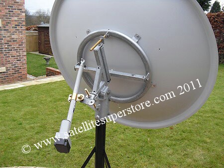
    images?q=tbn:ANd9GcSPvLnJTfza8cK6NGFowTIlYRiubUPKGWjeNilH_VgkQ3XvmWkW


    :pac:
    Actuation;

    primesatmotorised2.jpg

    Requires anchorage, 12v actuator, reduction of horizontal profile to about half what it is from the top of the pole attachment.
    Demounting of actuator, folding and road bracing to lock ratcheted flat for travel and storms. Effective ratcheting would probably require module corner supports.


    Actuator control link(add limit switches)

    $T2eC16N,!ykFIelv8bBKBSeS5KZo7Q~~60_35.JPG?set_id=880000500F

    Way cheaper and easier just get more cells. whistling.gif


  • Posts: 5,238 ✭✭✭ [Deleted User]


    Solar-Panel-Mount-sm.jpg

    Probably the more practical solution ;)
    Easy make a sturdier set than those online chancers are flogging. Soon as I think I've missed an opportunity to make good use of a set I'll knock 'em out. :P


  • Posts: 5,238 ✭✭✭ [Deleted User]


    What's the consensus about AC earthing to the chassis?

    http://www.smartgauge.co.uk/earthing.html

    ..just pretend "fresh water" = tyres


  • Posts: 5,238 ✭✭✭ [Deleted User]


    Traffo charger works great. The TS can compenstate for loads within a second so I can run 12v appliances without fear of overcharge. But it's so effin' noisey I can't be in the van when it's charging. It's like a lower frequency cathode ray tube TV hum at twice the volume. Any suggestions how I can shut those impudent worker bees up? Ground loop? Capacitor? Power factor loop(already has one of those though)? It's definitely TS related, it's fairly quiet when it's isolated.
    I'll see if proper earthing makes any difference as that's on the cards anyways. :o

    Another drawback inherit in the setup is solar charge naturally soft starts and slowly ramps up voltage over time the traffo just horses out max volts from the get-go. Hmmm.
    Traffo does get quite warm too but given that the entire case is one giant heat sink I'm not quite concerned about this.
    Oh well it is what it is and if it explodes I'll admit defeat.


  • Advertisement
Advertisement