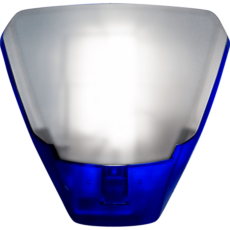
KoolKid wrote: » In most cases yes. Can you post the connections required at the bell.?
Dervbartlett wrote: » Yes the terminals are 1 Backlight disable 2 T 3 T 4 Eng hold 5 STB 6 BELL 7 bell + 8 bell - My six wires from main board are Strobe + and - Tamper resistor Sab hold (bho) External bell + and - Hope this is ok. Thanks
KoolKid wrote: » Yes the terminals are 1 Backlight disable 2 T 3 T 4 Eng hold 5 STB 6 BELL 7 bell + 8 bell - Try this... A pic of the bell would be nice to see if possible. Strobe - >>>>>>>STB Tamper resistor >>>> Second T Sab hold (bho) >>>>to Top Tamper (T) External bell + and - >>>>>>External Bell + & -
altor wrote: » Id say its a delta bell. 2 T Yellow, Tamper return Panel 3 T One leg of resistor 4K7 Linked to bell - in external bell 5 STB Green, Strobe - Panel 6 BELL Black, - External bell Panel 7 bell + Red, External bell + Panel 8 bell - Leg of resistor with Blue in bell, BHO Panel
Dervbartlett wrote: » It’s a pyronics bell. Is that the same ?
altor wrote: » Yes, that is the delta bell.
Dervbartlett wrote: » Hi I’ve just checked what I wrote and I’m slightly wrong what I said. It’s a pyronic bell and my options for inputs are Backlight disable T T ENG HOLD STB BELL + - Then the six wires from main panel are Tamper return Sabb hold there’s already a risistor between the 2 connections External bell + and - Internal bell + Fire p.a alarm disarm arm
altor wrote: » You just wont be using the ENG HOLD in bell. The system has other outputs but you wont be using them for external bell. The resistor in the control panel needs to be taken out. Resistor goes in External bell. Blue cable goes into BHO in panel. Yellow cable goes into tamper return in panel. Red Cable goes into External bell positive in panel. Black cable goes into External bell minus in panel. Green cable goes into strobe minus in panel.
Dervbartlett wrote: » Hi and thanks for the reply. Unless I’m reading this wrong you are telling me the inputs on my alarm panel. The cables are already in my panel. An engineer came a few months ago and removed the tamper return and sabb hold from panel and I assume put the resistor between the 2 connections to stop a fault showing on control panel. I’ve removed resistor and put the 2 cables back in. I’ve got this new bell but then the inputs are different. Hence the reason I’m struggling. So I actually need to know where to put the cables into just the bell end. Or are you saying I need to change the panel end aswell ? Thanks for the help.
altor wrote: » Yes that is the panel connections. I would disconnect before installing new bell. Bell connections 2 T Yellow 3 T One leg of resistor 4K7 Linked to bell - in external bell 5 STB Green 6 BELL Black 7 bell + Red 8 BHO - Blue wire with other Leg of resistor together
Dervbartlett wrote: » Thanks I will try that tomorrow again.
altor wrote: » No problem, any other issues let us know.
Dervbartlett wrote: » That worked brilliant thanks you. Another couple of questions if that’s ok. My internal sensors sense I’m walking around as they flash but don’t actually set off alarm. I’ve completely defaulted system to factory settings so do I need to set them in engineers menu. Also can I set up part set alarm as it says on cover so only external settings are active. Thanks again.
altor wrote: » You would need to see what way they are wired into the system. Can you open one sand take a picture? Yes part set is set up in the zone menu, zone options, select yes in PGA and or PGB.
KoolKid wrote: » The wiring is correct for duel end of line configuration. Check in zone hardware that the zone is set up for Duel EOL. Does the sensor activate in walk test?
Dervbartlett wrote: » Hi again. My alarm don’t activate on the walk test. The light flashed but don’t actually activate. And sorry not sure how to check if it’s set up for EOL. I’ve went through settings but can’t find it. Could you explain to me how to find it ? Thanks.
altor wrote: » In zone menu, zone hardware, change zone to duel end of line.