Advertisement
If you have a new account but are having problems posting or verifying your account, please email us on hello@boards.ie for help. Thanks :)
Hello all! Please ensure that you are posting a new thread or question in the appropriate forum. The Feedback forum is overwhelmed with questions that are having to be moved elsewhere. If you need help to verify your account contact hello@boards.ie
Hi there,
There is an issue with role permissions that is being worked on at the moment.
If you are having trouble with access or permissions on regional forums please post here to get access: https://www.boards.ie/discussion/2058365403/you-do-not-have-permission-for-that#latest

roller shutter door schematic

  • 08-03-2013 6:05pm
    #1
    Registered Users Posts: 221 ✭✭


    would anybody have a link 2 a diagram for a roller shutter door including two contactors , mechanical lock and limit switch.

    basically a forward revers schimatic

    thanks:D


Comments

  • Closed Accounts Posts: 1,521 ✭✭✭JustRoss23


    ah phase 6 plc i am almost sure we covered this. i will have a look and upload if its what your after:D


  • Registered Users Posts: 221 ✭✭kelledy


    yes it was even covered in ph 4 and dat would be better for me as there is no plc .. i have a fair idea but id rather a guide so i can just fire through it .. thanks


  • Registered Users, Registered Users 2 Posts: 19,340 CMod ✭✭✭✭Davy


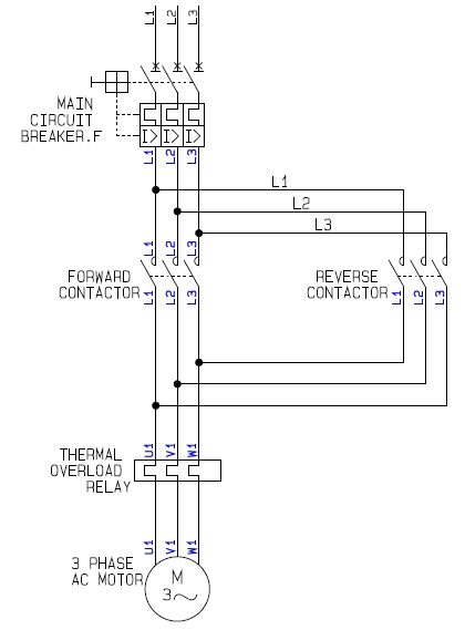
    Quick search popped this up, if its any use
    Forward+Reverse+AC+Motor+Control.jpg


  • Closed Accounts Posts: 1,521 ✭✭✭JustRoss23


    Spot on cheers davy:D


  • Registered Users Posts: 1,494 ✭✭✭m.j.w


    kelledy wrote: »
    would anybody have a link 2 a diagram for a roller shutter door including two contactors , mechanical lock and limit switch.

    basically a forward revers schimatic

    thanks:D

    Is it an electrical interlock your looking for? The diargram above is the mains circuit for forward reverse but you will need a control circuit diagram for the electrical interlock and limit switches. The mechanical interlock is just the little yoke you put between the two contactors


  • Advertisement
  • Closed Accounts Posts: 1,521 ✭✭✭JustRoss23


    come on mjw hope it out of your notes mate;)


  • Registered Users Posts: 1,494 ✭✭✭m.j.w


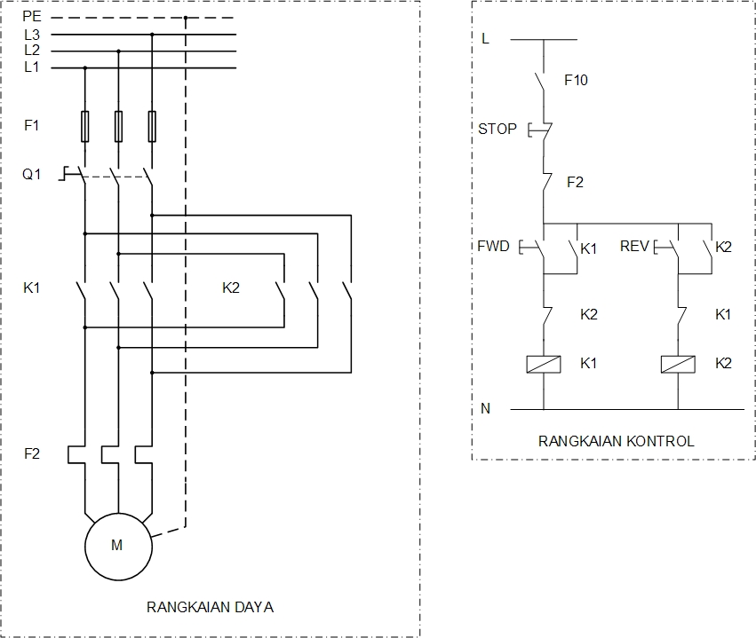
    fr.jpg

    Theres the control circuit there but it doesnt have the limit switch. The limit switches can just be wired through a n/c in series after each of the push puttons.


  • Registered Users Posts: 1,494 ✭✭✭m.j.w


    JustRoss23 wrote: »
    come on mjw hope it out of your notes mate;)

    haha my notes were in the bin once i got my results


  • Closed Accounts Posts: 13,422 ✭✭✭✭Bruthal


    m.j.w wrote: »
    fr.jpg

    Theres the control circuit there but it doesnt have the limit switch. The limit switches can just be wired through a n/c in series after each of the push puttons.

    Also, on shutters the hold on contact would probably be left out on the downward control, so if the REV button was for shutter down, K2 would be left out so the down button would have to be held in to close the shutter.


  • Closed Accounts Posts: 13,422 ✭✭✭✭Bruthal


    A lot of roller shutters are single phase as well, needing just a phase to either the up or down switch wire of the motor.

    The control circuit will be the same as above, and the power circuit similar, except one contactor or relay switches on the up feed, and the other the down.

    They are simple circuits anyway, once an understanding of exactly what is happening is gained.


  • Advertisement
Advertisement