Advertisement
If you have a new account but are having problems posting or verifying your account, please email us on hello@boards.ie for help. Thanks :)
Hello all! Please ensure that you are posting a new thread or question in the appropriate forum. The Feedback forum is overwhelmed with questions that are having to be moved elsewhere. If you need help to verify your account contact hello@boards.ie

Solar Install; the on-going saga

Options
1679111217

Comments

  • Posts: 5,238 ✭✭✭ [Deleted User]


    Ah it's only a trickle charger. If it was running 24/7 it'd hold it's own.

    The thing I've learned about wind turbines is if you want them to be practical you have to make them big (2m to 3m blade diameter or larger; there's an exponential increase of output with swept area) and steer clear of the non-propeller style gimmicky moving ornament crap.

    I could possibly get ~40W with a 3 phase Hugh Piggott alternator of a similar scale.


  • Posts: 5,238 ✭✭✭ [Deleted User]


    Those are some highly impressively quiet blades. Kudos that man!
    Alternator is flying at about 200Hz on a free standing mast and other than the vane rattle (play in the rivets) and the cogging hum, it's just a whisper above the wind (sorry no tachometer, I think it's a 24 step rotation).


  • Posts: 5,238 ✭✭✭ [Deleted User]


    Wooden roof-boxes :rolleyes:
    I started dismembering it with a drill and finished with a boot...
    DSC_0850_zps0f2722ed.jpg
    Delamination


    DSC_0852_zpsaa947f7e.jpg
    Mk - 2 Aluminum Edition


  • Posts: 5,238 ✭✭✭ [Deleted User]


    My traffo is having a rest. Haven't had time to take it into the surgery. After a preliminary investigation I found a fried thermistor (in-rush limiter).

    Thermister_zps48f0120b.jpg

    I'm going to have a go at salvaging components off the 110VAC side of the board to get the 220V back up.
    It's been running in overdrive (tied to a 45A solar controller). I thought when I was getting a 24v 15A traffo I'd have a 24A @15V charger...which is possible with MPPT but with my PWM controller it's just a 15A charger and a convection heater. :o

    I've seen it produce nearly 17A sometimes so I'm actually impressed it lasted this long. If I can fix it I'm going to have a look at putting a current limiter on it to stop it from frying again. If I can't I, found a new cheap(ish) contender for a mains charger. Not programmable though, no voltage sense leads and not ideal set-points either...better than most all the same.
    I can take the frankinductor away, pull out a C/O relay and save five points of contact resistance on the solar module if I change tack and won't have to listen to those infernal bees anymore.


  • Posts: 5,238 ✭✭✭ [Deleted User]


    The electrolyte density is down to 1.260 per cell (fully charged monthly equalisation) and there's flakes of gubbins in the electrolyte, lead dioxide clumps I suspect. I believe this to be due to short-cycling. I've been trying to deep cycle the batteries (40% DOD) the last few days and they're still sitting at 82% (running fridge on the inverter for 3 days now, not nights though as well as usual loads). I could disconnect the PV of course but, but, but.... :eek:
    Updated controller figures;

    Batterymin_zps699a98ab.jpg

    Battery Voltage Daily


    FloatDaily_zpsb1080965.jpg

    Full charge weekly
    (graphing time in float daily)


    BattTemp_zpsf6162eb3.jpg

    Battery Temp. Max/ & Min.

    (36°C is body temperature...fiddling with the thermocouple)


    TSreadingAugust_zps8f2ba62c.jpg

    State Reading
    (I don't know why my sense voltage is so low...might have a look at the fuse holder)
    kWh since last reset (3 months)


    AhDailyAug_zps9f1cdf93.jpg

    Ah Daily


  • Advertisement
  • Closed Accounts Posts: 1,638 ✭✭✭moodrater


    The electrolyte density is down to 1.260 per cell (fully charged monthly equalisation) and there's flakes of gubbins in the electrolyte, lead dioxide clumps I suspect.

    Considering the gear you have its real proof of how difficult wrangling battery chemistry is.


  • Posts: 5,238 ✭✭✭ [Deleted User]


    They're like onions M.
    It's nigh 150yo technology. 3 stage chargers are relatively new as is temp. compensation.

    Have you looked at lithium storage at all? Manufacturers are still arguing on charge recommendations. Individual cell monitoring of voltage, current and temperature. Super volatile. Conditioning for bank expansion. Electronics on the battery and on the charger, near linear (horizontal) voltage discharge curves...svengo.gif
    I'm still not convinced on the hype. The only benefit I see is the weight. Lead is still holding it's own on numbers and durability.


  • Closed Accounts Posts: 1,638 ✭✭✭moodrater


    3 stage chargers are relatively new as is temp. compensation.

    Wife flattened battery completely with parking lights on friday, new fangled charger says battery damaged refuses to put more than a few ma into it. So out comes the 30 year old bosch lump of laminated ion and discrete rectifiers. :rolleyes:

    I've only dealt with mobile device lithium batteries. If the voltage gets too low the battery pack itself will refuse to charge let alone the charger. I've brought a few 4-10ah ones back from the dead with a tiny usb charger from olimex. still a scary process.

    They haven't worked out very well for boeing!


  • Posts: 5,238 ✭✭✭ [Deleted User]


    moodrater wrote: »
    Wife flattened battery completely with parking lights on friday, new fangled charger says battery damaged refuses to put more than a few ma into it. So out comes the 30 year old bosch lump of laminated ion and discrete rectifiers. :rolleyes:

    Intelligent is to battery chargers what modulated is to inverters :D

    I just use another battery in parallel when that happens and charge across them.

    There's hybrid ships now running on Lithium. From what I hear they didn't bother with the cell monitoring in favour of the cheaper bank monitor solution.
    That'll be interesting to see what happens. :pac::eek:


  • Posts: 5,238 ✭✭✭ [Deleted User]


    The electrolyte density is down to 1.260 per cell

    I found this from Crown in my investigations (suspecting a grumpy solar controller next)


    SG_zpsad91a39b.jpg


    Untitled_zps9a9a4e0d.jpg

    I'm not entirely convinced it's so (like they say 12.6v is fully charged :rolleyes:), but I have just watered the batteries so perhaps I'll allow that margin for error for the time being...and not that I let the batteries rest for 24hour either. I've reassimilated the lead dioxide with a deep cycle.

    Traffo is dead like dodo. I got the 110V side up for 5 mins on a resurrected 110v site traffo until it blew a line filter cap because I mistook the replacement thermistor with a ceramic capacitor, replaced the blown electrolytic cap and a genuine thermistor and lost the regulator, then gave up.

    The replacement if any needs to be current limited. PV modules are current sources this is what the TS expects so anything I put on it will over-current unless it's over-rated which might damage the TS or the batteries are nigh full and then's it's just inrush I have to worry about.

    Lost a 3.8A charger too...it gave up the will to live after 14 hours slogging it and the PV came online brandishing a PWM wave in it's vicinity.

    The death toll continues;
    Tristar: 3 - cheapo mains chargers: 0

    Anyone know of a current limited 20ish amp 16V PSU? (not a lab supply....haven't got that kind of real estate in the leky closet).
    I'm tempted to quit while I'm behind and buy the Victron except the absorption is too low and the float's too high. Nothing programmable in mains-land for under €250.

    I may have to build a 20A current limiter but don't fancy the bees returning. Although on closer inspection of the SMPS it's the MOSFETs (type of gubbins) that are generating the heat I may get away with insulating the internal inductors. hrmmmmm....

    Meanwhile I've been thinking of rewiring a 3 phase washing machine motor single phase :eek: and belting it to an alternator for an CV mains-charger dual purpose bench grinder :pac:
    ...I reckon that'll maybe peak 30% efficient :rolleyes:


  • Advertisement
  • Closed Accounts Posts: 1,638 ✭✭✭moodrater


    unless it's over-rated which might damage the TS or the batteries are nigh full and then's it's just inrush I have to worry about.

    Anyone know of a current limited 20ish amp 16V PSU? (not a lab supply....haven't got that kind of real estate in the leky closet

    I assume the TS will only draw as much current at its designed for. Does supply need to be 16v, doesn't the ts-45 go 8v to 72v. You'd get a quality used 750w-1000w gaming psu for very little on ebay. I have one here that will put out 100A on 12v rail for quad graphics cards; at 45A it wouldn't even break a sweat cost £35.

    [edit]I see they say its something to do with the output capacitance. Doesn't make sense to me but hey I can't see their schematic. [/edit]


  • Posts: 5,238 ✭✭✭ [Deleted User]


    That's what I would have thought M. but when I emailed Morningstar previously they are very concerned about being within spec of the controller. The manual advises to only load it to 80% capacity with Isc PV to allow for edging spikes and low temp. up-rating.
    That said the manual also says it'll take 130% under FET duress.
    I'm suspicious that being that it's tied to a current source it's designed to to grab what it can and run, unlike traditional voltage sources that sit in and around what current they demand. ...correct me if I'm wrong I haven't researched it a whole lot tbh.


    It has a wide input range but it's just a big buck regulator really and MPPT is a big buck/boost regulator with compensation for battery SOC.

    It'll happily power up at 9V and idly twiddle it's thumbs until it sees a voltage higher than the batteries then buck everything it deems fit up to 125V.

    Supply needs to be higher than my temp. compensated equalisation set-point inc. wiring and circuit losses.

    Computer PSU max out at 12V? Can any wizardry be done with the 5v and 12v rails to make a 17V output?

    Whadya make of this?

    POWER%20STRIP2-180x120.jpg

    Do you think I could parallel two 10A outputs for 20A? Or is that a manufacturer question?

    PS. My 3.8A charger dieing may have had more to do with overwork than the TS. Usually solar controllers read battery chargers as a charged battery and back off.


  • Posts: 5,238 ✭✭✭ [Deleted User]


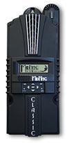
    This would be an ideal controller instead of the TS; Midnight Classic MPPT. Inbuilt current limiter, programmable from the unit, wider tolerances, larger capacity (not that i need it) ethernet port.

    classicNew_small2.jpg

    MPPT algorithms for wind and hydro...I hear it's a scary sight on a big windy. It takes the load off to let it spin up (static friction co-eff. defeat) then PWM's the best power curve.


  • Posts: 5,238 ✭✭✭ [Deleted User]


    3.8A charger back online. :D
    I read in some forum hitting it might help (tv fix :rolleyes:).
    So after repairing broken solder legs on the the mains LC from brutalisation (hitting solid state lekytronics rarely does much good :pac:), it was just the mode switch gave up. Swapped it out and she's good to go.

    Tristar; 2 - Cheapo mains chargers; 0 - Sir Liamalot; 1


  • Posts: 5,238 ✭✭✭ [Deleted User]


    Found the culprit of my battery sense. Someone and I won't mention who :pac: never secured the sense lead properly.

    GoodSense2_zps08fcb74e.jpg?t=1409852587

    It's the yellow crimp lug. The main conductor was stopping the screw that was holding it down from making a firm connection. Spring washer to the rescue.
    Let's see if that improves my S.G. If it does I'll know I've been overcharging for the last 4 months.

    GoodSense_zpse9629e66.jpg

    I can live with 20mV. I'll attribute that to the fuse resistance and conductor gauge.

    I'm also changing my policy on equalisation, I'm keeping the reminder to check the electrolyte monthly but I'm not equalising them if there's less than .015 points of difference between cells. I don't think they need it most of the time given my average discharge levels.

    [EDIT] : Steel is a rubbish conductor. The resistance is very high. If you must use steel washers like I did don't place them between conductors.


  • Posts: 5,238 ✭✭✭ [Deleted User]


    MainsCO_zps9f3f6fac.jpg

    Mains changeover relay folks 240v coil.

    (Cable tie is to keep the relay in the holder)


    InverterCO_zpsb6db37da.jpg

    Here's a Basic Layout
    (I'm not showing anyone how it really is :pac:...different sized MCBO's both ends, lights with switches and isolators either side...:o, light and sockets on the same cores....mains feed polar opposite corner from inverter...look at the pretty diagram...whistling.gif )


    I've now got ~150% more electrons flowing from my alternator to my house batteries per hour in the Summer, probably more in the Winter because my fridge is now running on a thermostat on the AC element from the inverter, which I've hard-wired through half my "ring main" on self-discriminating mains/inverter sockets (including the one I use for battery charging :pac:).
    I can turbo boost my fridge when driving 12v + 230V = 225W :cool:-ing. Soon as fridge is down to temp. thermostat kicks out and fridge runs on 12v only.
    The fridge can now feasibly run from PV on selective occasions.
    I didn't convert all my sockets because I didn't fancy taking the walls and roof apart and in an effort to leave my dual source powered, triple circuit, 2-way switched overhead lighting well enough alone (here be dragons) there was no easy way to isolate them from 4 sockets. Eh. I've 2 dedicated inverter sockets. 5 auto-selecting and 4 dedicated mains sockets. Close enough.


    This is a potentially hazardous circuit for a few reasons.
    If you wire it incorrectly it'll neutralise your inverter (easy do with 8 poles). Depending on the inverter isolation I guess you might be able to explode your batteries.
    If you break the relay while running an inductive load at full capacity (2300W) I reckon you could get an arc to bridge the contacts and neutralise your inverter.
    If your connections/crimps fail it could neutralise your inverter...etc..
    Ingredients_zpsdb31d516.jpg

    Ingredients:
    3U DIN Rail box
    DIN rail mountable relay holder.
    240V DPDT relay with 240V coil.
    Cable entry glands/grommets.
    Crimp ring terminals (not pictured).
    Labels


    Coil_zps8c3b2c5b.jpg

    Coil Terminals


    Switchtestlowinverterthruput_zps47b4dc12.jpg

    Inverter Throughput Closed (coil not energised)


    Switchtestlowmainsthruput_zps5af24b53.jpg

    Inverter Throughput Open (coil energised, monitoring inverter)


    Switchtesthigh_zps35edaae3.jpg

    Mains Throughput Open (coil energised, monitoring mains).


    I needed to extend a core-set to the relay position. Normally I just pull out the old cable and run a new cable instead. I hate connector blocks. In this case that meant pulling out half the conversion and a third of the roof...as needs must I made the exception and butt crimped this one with a real crimping tool and heat shrink.
    Buttcrimpextension_zpsc293c147.jpg

    Butt Crimp Extension

    I don't really care for solder for a vibratey camper application, I prefer the flexibility of crimps, I think solder makes things rigid and more inclined to break...how and ever I've never seen a solder joint fail on a vehicle all the same...not that I have many.
    WiredLabelledBuried_zps7833ea1d.jpg

    Wired, Labelled, Buried


    Everything tested and working! :)

    PS. If you're testing a MSW inverter on a non-RMS multimeter you'll get some funny numbers off the dirty sine wave ~150V-190V AC.


  • Posts: 5,238 ✭✭✭ [Deleted User]


    I relented I got the Victron 1215

    Victron_zps1fb82669.jpg

    Putting it through it's paces at the minute. Unfortunately I'm completely outtov discharged batteries. :D

    Chargerwise my little Aldi 3.8A despite it's many, many flaws (over-charge, overheat, non-load compensating, unreliable float into equalise into charge into equalise mode (unit does not come with an equalise function! :rolleyes:)) puts just as many electrons into the batteries as the Victron albeit requiring of a babysitter and a fan mod.
    Yeah I know, apples and oranges.

    It'll be a few weeks maybe months before I can put it beside the TriStar and see how it fares.

    I've no idea where the temp sensor is. I can only guess it's internal in that IP65 sealed case with passive cooling populated with resistors and heat-sinks. :rolleyes:
    Probably why it takes a one time reading in the test stage and then a final one in float and storage (storage = 13.2V float after 48 hours with weekly rebulk).

    The absorption stage is fixed 14.4v or 14.6v.
    Crown recommend 14.5v on mains for my set. I recommend 14.7v+ on PV. :p
    So I reckon they'll do. The TriStar can always finish the job anyways.

    The float is too high (13.8V...Crown say 13.5V). But the current is low.
    VFloat_zps97bb1085.jpg

    Victron Float (sunny worktop)


    The TriStar is floating at 13.6V & 400mA in the shade on another battery set elsewhere so maybe that's not something to worry about either.
    I might stick a schottky on the output, transistor switched via C/O relay from the charger float LED...if I get really pedantic.


    The feature I like the most is quiet, load compensation. My batteries never get a break.
    It's completely silent from outside the enclosure. bowdown.gif

    It'll also work as a 15A power supply without the batteries.
    Anyone wanna see what's inside a "94% efficient" charger?
    See attached. That's some top notch silicon.


  • Posts: 5,238 ✭✭✭ [Deleted User]


    :o


  • Posts: 5,238 ✭✭✭ [Deleted User]


    Not being one to give up on a good idea just because it's a bad plan I couldn't resist another shot at the traffo charger.

    I found this

    $_12.JPG

    It's a 20A 16V constant current, constant voltage adjustable PSU from China. :D
    I had a look inside and noticed it's populated with the world's most unreliable electrolytic caps, and the datasheet says 87% efficient with passive cooling. So there's about 40W of waste heat in that little aluminum can. :rolleyes:

    Ixnay that as a primary. I've ordered it's sister; the 32V 05A for just over half the price as a possibly sacrificial proof of concept.
    I'm going to replace the caps. maybe put in a few vents and a fan mod. depending on how it runs and test it as a back up charger through the TriStar. If it's crap I'll just use it as lab power...I've already spent more on HRC fuses with me aulde analogue jobbie. whistling.gif

    15A + 5A = 20A charger Mwahaha....well sortov...:pac:


  • Posts: 5,238 ✭✭✭ [Deleted User]


    This is kindov impressive for a mains charger (it's a low bar :p...small, expensive and Spartan by solar controller standards).

    It goes into storage mode after < 12hours (all the manual says is "It is therefore essential to reduce the voltage even further when the battery remains connected to the charger during more than 48 hours.")

    Looks like the float current is higher on the "High" algorithm. It's ~ 500mA @ 13.8v.
    FloatStorage_zps367cac16.jpg

    Storage Mode (14.4v absorption algorithm)
    Turning on and off loads doesn't effect the charging stage.
    Load Compensation is soft rise, soft fall. Battery fills the gaps to avoid hard switching I guess.
    LoadCompensationThroughBattery_zpsc412d5ef.jpg

    Load Compensation: through battery (~55W load)


    LoadCompensation_zpsd06fe809.jpg

    Load Compensation: Current to Battery Only (+42mA Cwaor that's accurate)


    Supply_zpse51930f3.jpg

    Supply (no battery).


    Back-currentdrain_zpscd7565ef.jpg

    Back-Current Drain 867uA (0.0009A...Cwaor)
    Bleed from batteries to charger when charger is off.

    Few more tests to run but they'll be a while.
    Equalise current and voltage.
    Heat sink temp. at full load.
    Who quits absorption earliest TriStar or Victron (my money's on Victron)
    I might test this 94% efficient claim if I could be bothered, although if they wanted 95% they could've just made the (12 AWG) charging leads fatter imho.


  • Advertisement
  • Posts: 5,238 ✭✭✭ [Deleted User]


    hysteria.gif
    PowerIn_zpsac60e28e.jpg

    Supply Mode
    AC Power In: 136.9W / DC Power Out: 68.4W

    :rolleyes: I make that 50% efficient @ 38% full load whistling.gif


  • Posts: 5,238 ✭✭✭ [Deleted User]


    I'm a little underwhelmed with this Victron in the end.
    Just a little though. I was very disappointed that after cycling from 40% DOD and then restarting an new charge cycle it called it a day @ SG 1.250. Then I put the batteries on the TS and it went straight into float too. smiley-bangheadonwall.gif
    That's actually saying a lot though because previously the TS has always outperformed my cheapos.
    I got 5 cells up to SG 1.275 last week after 4 days on PV float (13.5V) the last cell was 1.265 and having none of it (yup I spent a week looking for my last 1.6% charge :rolleyes:).
    I tried a C20 discharge in an attempt to re-balance the cells after equalisation did nothing and them 6v's are bang on 235Ah.
    I also swapped around the batteries so the weaker cell isn't in the middle anymore. Moved the temp sensor to the 0v post that gets the most sun (instead of the previous +6V post whistling.gif)

    It's all a bit too overcautious and tight-fisted with the electrons.

    Equalisation is set at 15V (25°C); 1 hour :rolleyes: (set-point not listed in the manual just a max of 16.5v)...kinda pointless; my requirements are 15.5V, 3 hours.
    I can't just equalise on it either, I have to bulk first and let it run through it's stages. So running it 3 times is just ridiculous. :mad:
    Basically just a hot cycle then.

    The manual says the EQ charge current is 1.2A and
    Victron wrote:
    "Some battery charger manufactures recommend pulse charging to reverse sulfation. However, most battery experts agree that there is no conclusive proof that pulse charging works any better than constant voltage charging. This is confirmed by our own tests."

    I metered it as a slow current pulse averaging 1.4A.

    Temp comp. is 2mV below standard recommended.
    Victron wrote:

    Ultra high efficiency “green” battery charger with up to 95% efficiency, these chargers generate up to four times less heat when compared to the industry standard.....
    ...
    ...Durable, safe and silent
    - Low thermal stress on the electronic components.

    Sink1_zpsee5227db.jpg?1410957904946&1410957909725

    I'd like to see any industry standard charger generate 4 times more heat and survive. :rolleyes:

    Victron wrote:
    Protection against overheating: the output current will reduce as temperature increases up to 60°C, but the charger will not fail.
    HotampStuffy_zps017eeee0.jpg?1410957904946&1410957909726

    It was 12.4A in the sun before I got the camera and the fan out.


    Looks like storage kicks in after ~3 hours.

    Storage load compensation sits exactly 0mA if you give it long enough on good batteries with a constant/no load.


  • Closed Accounts Posts: 1,638 ✭✭✭moodrater


    To be fair as an electronic engineer if I were designing something like this it would be very conservative too, you wouldn't want to be responsible for fires and explosions, you never know what what joe public will connect it to.

    I terms of heat you might well find out that whoever assembled it for victron has cheaped out on the mosfet or it could be a reprinted chinese special (I have some sram on my desk thats clearly been reprinted from 110ns to 55ns). Judging by the piddling heatsink they designed it for a very low rds.

    Unless you buy a fully programmable charger where you can set the battery chemistry, battery bank size etc. you're never going to get ideal charging. Even then ideal will be compromised by safety margins and the ideal charging profile is subject to debate.


  • Posts: 5,238 ✭✭✭ [Deleted User]


    That's understandable.
    From what I've seen discounting Sterling on reliability issues (but not warranty or customer service). You can get twice the charger for half the price with a solar controller and an external current limited supply. That said I've still to make it work. :o


  • Posts: 5,238 ✭✭✭ [Deleted User]


    moodrater wrote: »
    I terms of heat you might well find out that whoever assembled it for victron has cheaped out on the mosfet or it could be a reprinted chinese special

    The MOSFETs are International Rectifier (85°C @ full load with enclosure open ) [not an exact match, part number I have doesn't have letters at the end]
    The Bridge Rectifiers are Fairchild. (74°C)

    I've no idea if they're fake Chinese or not.


  • Closed Accounts Posts: 1,638 ✭✭✭moodrater


    The MOSFETs are International Rectifier (85°C @ full load with enclosure open ) [not an exact match, part number I have doesn't have letters at the end]
    The Bridge Rectifiers are Fairchild. (74°C)

    I've no idea if they're fake Chinese or not.

    Actually looking at it again, 85C translates to hardly any heat at all just a few watts given the size of the mosfet heatsink which looks like 12mm x 90mm something like 25 C/w. So it is very efficient.

    FSR2100 isn't a rectifier its practically a complete smps in a package thats doing most of the donkey work the mosfets must be a microcontroller driven secondary stage to regulate current and voltage.

    All in all with those temperatures at full tilt its probably dissipating around 10w which is pretty efficient!

    I'm guessing the duty cycle of the mosfets is fairly low so the gate charge is much more important than the rds so they couldn't do much better - maybe a 3306 but you're talking a few percent if any less dissipation.


  • Posts: 5,238 ✭✭✭ [Deleted User]


    I wouldn't be giving it such a hard time if they weren't making such audacious claims. I'm sure it can be 94% efficient at idle but not when it counts.

    AFAIK the electronics that requires isn't in mainstream production yet.

    The heat doesn't concern me a whole lot tbh...5 year warranty.

    It's still a very good charger. It's beating CTEK on price and functionality imho.

    Meanwhile I can force absorption on my TS with a big enough load for a few seconds to drop below my programmed float cancel set-point (12.3V)


  • Closed Accounts Posts: 1,638 ✭✭✭moodrater


    I wouldn't be giving it such a hard time if they weren't making such audacious claims. I'm sure it can be 94% efficient at idle but not when it counts.

    The heat doesn't concern me a whole lot tbh...5 year warranty.

    But it probably is that efficient, why don't you measure the input current andoutput current and voltage and calculate it.

    15A * 14.4V = 216W out so imaginign 94% efficiency say 230w in.

    6% of 230w = 13.8W

    I'm guestimating the small heatsinks at 25C/W and the large one at 15C per watt. So the first stage is dissipating something like 4W and the mosfets something like 3w each = 10W which leaves 3.8W for inductor, capacitor, diode, copper losses etc. which is feasible.

    Lower duty cycle increases switching losses so it should be more efficient at full tilt.


  • Posts: 5,238 ✭✭✭ [Deleted User]


    http://www.boards.ie/vbulletin/showpost.php?p=92158684&postcount=262
    :P

    Can't measure it accurately at full tilt unless you want to sponsor me a DMM 10A HRC Fuse?
    I'll have a look at it on the TM at some stage I'm city-slicking it at the mo. so can't run an EHU, or meddle with big machines or smite things after hours...:(


  • Advertisement
  • Posts: 5,238 ✭✭✭ [Deleted User]


    It's a steady 58% at full load. By the time it reaches 14.6v it's already switching to reduce internal heat so higher volts doesn't improve efficiency.
    Worldleadingefficiency_zpse1f2a23a.jpg?1411411089649&1411411092585

    337W In / 197W Out @ Full Load= 58% efficient


Advertisement