Advertisement
If you have a new account but are having problems posting or verifying your account, please email us on hello@boards.ie for help. Thanks :)
Hello all! Please ensure that you are posting a new thread or question in the appropriate forum. The Feedback forum is overwhelmed with questions that are having to be moved elsewhere. If you need help to verify your account contact hello@boards.ie

Spitfire Total Rebuild!

Options
17810121316

Comments

  • Registered Users Posts: 4,504 ✭✭✭SpitfireIV


    And we have color..........


    :D


  • Registered Users Posts: 1,258 ✭✭✭sogood


    Looking good. I can imagine your sense of achievement. Putting down paint is certainly a corner turned, although your rebuild has more corners than the Hampton Court Maze!

    I was the same when doing up my boat. No matter what I did, I never felt to be near the home stretch until it was painted. Looking forward to seeing more and hats off to your patience and dedication.


  • Registered Users Posts: 4,504 ✭✭✭SpitfireIV


    sogood wrote: »
    Looking good. I can imagine your sense of achievement. Putting down paint is certainly a corner turned, although your rebuild has more corners than the Hampton Court Maze!

    I was the same when doing up my boat. No matter what I did, I never felt to be near the home stretch until it was painted. Looking forward to seeing more and hats off to your patience and dedication.

    Bit of color makes all the difference indeed! :o Feels like its getting somewhere now! Cheers.


    Been busy enough over the past few days. Got the sump and petrol tank welded up have the engine more or less finished now and the brake lines on the chassis have been completed! Little video for your viewing pleasure.....


  • Registered Users Posts: 12,917 ✭✭✭✭Toyotafanboi


    4016048.jpg

    really enjoying this thread.


  • Registered Users Posts: 4,504 ✭✭✭SpitfireIV


    4016048.jpg

    really enjoying this thread.


    Hah, nice one! :D


    You might be able to help me out on this one. The Spitfire has two main dials, those being the speedometer and the rev counter. Now, the Speedo is run off the overdrive unit on the Triumph gearbox, so, thats grand, the rev counter however would have been run via a cable from the distributor.

    My standard Starlet doesnt have a (I presume electronic) rev counter, but, what I was thinking was trying to pick up a instrument cluster from a glanza, or corolla or some such and using the guts from that to graft into the original rev counter dial, ie using the original dial face and needle but with the inner working from the Toyota. Wiring it up however is another thing, I assume I'd need the plugs for it and it'd have to go back through the ECU? etc....

    Kind of at a loss, so, any help would be appreciated! :)


  • Advertisement
  • Registered Users Posts: 185 ✭✭pryantcc


    Great work here! I'm not familiar with your Starlet engine but it should be pretty easy to get a source for the tacho. There's a distributor on the Starlet, right? It's not an ECU job??
    You should be able to just hook your Triumph tacho to the Starlet distribitor with no need for messing around. Am I missing something?


  • Registered Users Posts: 12,917 ✭✭✭✭Toyotafanboi


    yeah, i don't claim to know a huge amount about electronics by any means, but if you are using the mechanical drive speedo and you are using the existing Triumph fuel level sender (?) then you really don't need to keep any of the Starlet instrument cluster wiring at all.

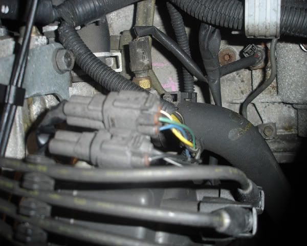
    you could take RPM signal from the green wire in the loom at the distributor here
    coil2.jpg

    or from the ECU at pin "NE" here (6th from the left on the bottom row) if that's handier
    990238d1252379940-charade-87-undergoing-swap-suggestions-welcome-toytccs_pins_4a-fe_map_gao_pakwheels-com-.jpg

    and just connect that to where the old signal wire would have went on the Triumph tacho?

    i stole both those images from google, so they could go anytime.


  • Registered Users Posts: 4,504 ✭✭✭SpitfireIV


    pryantcc wrote: »
    Great work here! I'm not familiar with your Starlet engine but it should be pretty easy to get a source for the tacho. There's a distributor on the Starlet, right? It's not an ECU job??
    You should be able to just hook your Triumph tacho to the Starlet distribitor with no need for messing around. Am I missing something?


    Thanks! ;)

    The Triumph rev counter was controlled via a cable connected to the dizzy at the point illustrated in the below image. As far as I'm aware the Toyota rev counter is electronically controlled as I can see no mounting point for a cable, but, I'm not sure, just another little issue to be sorted :)

    dizzy.jpg


  • Registered Users Posts: 12,917 ✭✭✭✭Toyotafanboi


    is that mechanically driven too? distributors were before i was born :pac: so the above method won't work then?

    even at that then, you'd probably be better to buy a cheap simple aftermarket rev counter and dis assemble it and use the method above because the one on the Starlet gauges is part of a printed circuit and it really would be a pain in the arse to make that happen.

    edit: something like this
    http://shop.mcgautostyling.com/browse-by-parts/engine-performance-dress-up/electronics/meters-gauges/classic-style-rpm-gauge-for-all-cars-universal.html

    green wire or pin NE above to this, then all it needs is power and earth. i'd say one of these would be easily butchered to meet your needs :pac:


  • Registered Users Posts: 1,258 ✭✭✭sogood


    As usual, loving this thread. Regarding the reflectors, when mounting them, I would tend to position them further out towards the corners of the bumper, thus more accurately reflecting (no pun intended) the width of the car. It will probably never happen, but if you were parked in a badly lit area, you don't want to give the impression that your car is narrower than it actually is.

    Just a thought.


  • Advertisement
  • Registered Users Posts: 4,504 ✭✭✭SpitfireIV


    is that mechanically driven too? distributors were before i was born :pac: so the above method won't work then?

    even at that then, you'd probably be better to buy a cheap simple aftermarket rev counter and dis assemble it and use the method above because the one on the Starlet gauges is part of a printed circuit and it really would be a pain in the arse to make that happen.

    edit: something like this
    http://shop.mcgautostyling.com/browse-by-parts/engine-performance-dress-up/electronics/meters-gauges/classic-style-rpm-gauge-for-all-cars-universal.html

    green wire or pin NE above to this, then all it needs is power and earth. i'd say one of these would be easily butchered to meet your needs :pac:

    Thanks for that info ! Very helpful, been looking into it a bit more and it seems the best route is to buy an after market tacho and take the guts out and fit them to my original dial. I'll be sure to let you know how I get on! :)
    sogood wrote: »
    As usual, loving this thread. Regarding the reflectors, when mounting them, I would tend to position them further out towards the corners of the bumper, thus more accurately reflecting (no pun intended) the width of the car. It will probably never happen, but if you were parked in a badly lit area, you don't want to give the impression that your car is narrower than it actually is.

    Just a thought.


    That makes perfect sense and something I hadnt thought of to be honest! ;) Gave it a shot and I think they do work better further out on the bumpers....

    12669548_10156436268120591_181603496864730100_n.jpg?oh=a017c53a5a6ed59a5a51dc7a4444ab23&oe=5734FAF5

    12669627_10156436268570591_7597972320683052823_n.jpg?oh=56fa05a98727b468549165c2f0f15f4c&oe=572B02A7


  • Registered Users Posts: 4,504 ✭✭✭SpitfireIV


    Much work was done today! Watch this space ;-)


  • Registered Users Posts: 4,504 ✭✭✭SpitfireIV


    Y'all might like this update! ;)


    12688012_10156459903165591_2883830008992141477_n.jpg?oh=fde1b1590e49c61f5fbf9f6c15baf7c9&oe=572F4432
    Tub all wrapped up with somewhere to go! Well, it was raining out.


    12642565_10156459903395591_1245710879596286135_n.jpg?oh=25cd80b15ce234688f1776feacfa4708&oe=5766FC7D
    Rain stopped tahnkfully, so, into the back of the van for a little journey.


    12654364_10156459903580591_2017807590627043840_n.jpg?oh=c87b206f2ce8359c161c8c8cdd9bdb18&oe=576420C0
    Out came the chassis from the poly tunnel (that is holding up surprisingly well with all the recent storms we've been getting!).


    12661961_10156459903930591_345791002101317270_n.jpg?oh=571ec3c316434f73824a7336b3a9f19d&oe=57678EA6
    Engine next to the chassis? Must be time to put it in so!


    12688314_10156459904140591_3904754617459157430_n.jpg?oh=05d78682ac1f9ec025dc9af6d17f44ba&oe=57336B3F
    And 'jus like tha' the engine and box were bolted up and the two fixed onto the chassis! Well, three of us lifting and hauling got it in. Lined up perfectly with the gearbox mounting bracket, result!


    12642950_10156459904310591_3430122262845040840_n.jpg?oh=147a0d7e1f73cfae1bc523a230047bfd&oe=576D5DFD
    Shot from the opposite side.


    12647258_10156459904435591_4236142352040650020_n.jpg?oh=13fd171b3a51f41429942b7360fd720c&oe=572A020F
    Shot showing the DIY engine mounting bracket. The observant amoung you will notice just two pulleys; the alternator hasnt been fitted yet and will be a DIY job.


    12670055_10156459904850591_1165527700551734590_n.jpg?oh=c311b3f18502362406d96cb09c9045c7&oe=5731B1DD
    Side shot! If I havent said it already, those rear wheels will be going!


  • Registered Users Posts: 4,504 ✭✭✭SpitfireIV


    12669527_10156459905005591_4242930813395574976_n.jpg?oh=d920995c570cd18ed33bbf1dfc60b814&oe=5734D55D
    Tub out of the van ready to be reunited with its chassis.....


    12654502_10156459905200591_2582695916639500992_n.jpg?oh=35bd5eb1efd2802b07f7412df87ea4d5&oe=572E588A
    Another bit of huffing and puffing and boom.........you have a car!! :D


    12654257_10156459905610591_1673428367736333384_n.jpg?oh=5f33eaf1196ba07336607179cd192df1&oe=573B8A73
    Rear end.....showing the modified rear lights.


    12662419_10156459905815591_707879599311094765_n.jpg?oh=7dae5c13c13977198388ab88644c904a&oe=572D4B91
    GRP GT6 bonnet lifted on for a look see.......fit is not too bad at all and the look is great!! Well, apart from the rather large wheel arch gap; lowering springs or some other solution will definately be needed! ;)


    12670073_10156459905940591_2649012214556617399_n.jpg?oh=5a0e2591e13b7cccf1733ae4fd457a36&oe=5738D54E
    Vroom vroom......couldnt resist an imaginary drive :P


    12651339_10156459906110591_1020074184950594854_n.jpg?oh=5d13871d4ae6f942482732b6d70491ff&oe=576587E0
    Put away for the night after a long afternoon/evenings work! :)


    More to follow..........


  • Registered Users Posts: 4,940 ✭✭✭Bigus


    Big milestone , well done.

    Looking at the engine and gearbox mountings , l'd be considering an extra mounting or steady bar ( a la mini ) just in front of the bell housing to resist twist, I just think there is too much distance between front engine mounts and the one gearbox mount , maybe look at how an mx5 is set up for guidance.

    However great work by you.


  • Registered Users Posts: 699 ✭✭✭Zebrano


    The mk 1 mx5 has two mounts one either side of the engine then the gear box is connected th the diff via an aluminium rail its not connected to the body. So the engine gearbox and diff are essentially one unit held on with 2 nuts and 2 bolts.

    Good work by the way.


  • Registered Users Posts: 4,504 ✭✭✭SpitfireIV


    I dont see any issues with the engine mounting at the moment, its mounted using the same bracket as the Starlet, but, I can see what youre saying; its a long ol' lump so I'll monitor it. If needs be a bracket or two could easily be made up to attach to the bell housing plate and then to the chassis.


    Some moar....


    12705318_10156466484035591_7301798151627349434_n.jpg?oh=c9ed4b90e315f097d62b541680ea3382&oe=5722E8D2
    Few more bits attached to the engine, partial wiring harness fitted and copper lines ran from the master cylinders.


    12717904_10156466484165591_2282474868337850876_n.jpg?oh=63135c902334c69af9211995e8fc0bbf&oe=576E693F
    Few problems encountered were just how tight the leads in the distributor are to the bulkhead!! Hopefully I wont need to be changing them. The bit of relieving done on the bulkhead means the copper lines had to be tracked further and so are not long enough, but, thats an easy fix. Wiring harness will also need lenghtening in areas so as to reach certain plugs etc, again, not a big job.


    12509008_10156466484555591_5740668658364634830_n.jpg?oh=e50e3628d69dd0f95d745960062dcaf1&oe=576551D4
    Unfortunately the air intake on the throttle body is pointing bacward, again, shouldnt be an issue as once it's up and running this standard set up will be replaced by Honda CRB throttle bodies.


    12651221_10156466484840591_116120334214102902_n.jpg?oh=826a1b47f9a7edc6a9793071c6375ba7&oe=576E6562
    Dropped the rad in for a look'see, seems it will fit ok with a few brackets made up to secure it eventually, it will have to sit at an angle as such to accomodate the height of the bonnet.


    12654436_10156466485205591_9135506697534812150_n.jpg?oh=c3170f6aae42585e9ce6a9e60323f058&oe=5729BA6B
    Front view! Again, serious lowering needs to be done on the front! Just goes to show how much lighter the Toyota engine and bonnet are compared to the Triumph lump and steel bonnet!


    12717900_10156466485520591_7281035102708258710_n.jpg?oh=d4b65b19d933e5d841169d2b8672db36&oe=572785CB
    12717528_10156466485690591_2296463798961392732_n.jpg?oh=31e53ae25410c05ccd37e7555d9b7e8a&oe=572BA9CD
    GRP bonnets are usually noted for bad fit, but this one seems to be pretty tight! The only issue is over the passenger side sill there is an even gap, but, that'll pull out easy enough, so I'm not worried.


    12705358_10156466485815591_914058194888785940_n.jpg?oh=ae740c81d887b8d83aa7aaf0a827ef6c&oe=5737FC77
    I like the look! :D


    Below you can see moving pictures with sound!


  • Registered Users Posts: 12,917 ✭✭✭✭Toyotafanboi


    That's a massive turning point for you, it's like you've gone from various piles of odds and ends to an essentially complete car in an afternoon. That must give you a good motivtional boost to keep moving :)


  • Registered Users Posts: 13 stevesxm


    new to the board and had a career in motorsports before retirement.... was a national champion in a spitfire in 79 . your project is quite amazing and i would have some suggestions to make but most important first.... i admit that i have not read the detailed 11 pages of this thread and maybe you have covered this elsewhere... you have had the body off the chassis do to a lot of this work as you should have... what you may not know or have noticed is that there are shims under the body mounts... some soft and some rigid. these are really important. if you leave them out or put them in the wrong order or if they are worn or whatever , what you will find is that when you bolt the body down and then try to hang the doors, they aren't going to fit by a lot.... like a 13mm overlap or a stick your fingers in the gap sort of thing. the body actually bends across the door opening when its bolted down and the amount it bends is determined by those shims.... if you have already taken care of that then good for you for being clever... i won't tell you about the first one i built in 72 that, after i got done welding the roll cage in it , and bolted it back down you could have walked into the car without opening the door the seam was so wide...


  • Registered Users Posts: 4,504 ✭✭✭SpitfireIV


    That's a massive turning point for you, it's like you've gone from various piles of odds and ends to an essentially complete car in an afternoon. That must give you a good motivtional boost to keep moving :)

    Hey, thanks! :) I'm still finding it hard to believe that I have something that resembles a car now, its a massive boost indeed!
    stevesxm wrote: »
    new to the board and had a career in motorsports before retirement.... was a national champion in a spitfire in 79 . your project is quite amazing and i would have some suggestions to make but most important first.... i admit that i have not read the detailed 11 pages of this thread and maybe you have covered this elsewhere... you have had the body off the chassis do to a lot of this work as you should have... what you may not know or have noticed is that there are shims under the body mounts... some soft and some rigid. these are really important. if you leave them out or put them in the wrong order or if they are worn or whatever , what you will find is that when you bolt the body down and then try to hang the doors, they aren't going to fit by a lot.... like a 13mm overlap or a stick your fingers in the gap sort of thing. the body actually bends across the door opening when its bolted down and the amount it bends is determined by those shims.... if you have already taken care of that then good for you for being clever... i won't tell you about the first one i built in 72 that, after i got done welding the roll cage in it , and bolted it back down you could have walked into the car without opening the door the seam was so wide...

    Hi Steve, thanks for the response, any info or pointers you have I'd be more than happy to hear :)

    I've read many many conflicting views on the tub to chassis spacers, what type goes where etc etc. In the end I went with six spacers to essentially fill gaps; two alloy ones under the front bulkhead mounts, two alloy ones above the rear leaf spring mount and two rubberised ones at the seat belt mounts. The body seems to be sitting fine at that and all mounts are tightned down with no ill effects on door gaps. If you have read back further you might have seen that I added some extra re-inforcing to the mid sill in the form of a lenght of box section with outriggers running into the cabin, so that would take a lot of flex out of the tub......

    1529912_10154286153480591_242520806386076331_o.jpg

    10431394_10154286154090591_6998441240901113499_o.jpg

    10476380_10154286154060591_3884772927123790969_o.jpg

    10511564_10154286154085591_3818941414390134525_o.jpg


  • Advertisement
  • Registered Users Posts: 4,504 ✭✭✭SpitfireIV


    Update time ;)


    12729381_10156501058690591_3952977374374101061_n.jpg?oh=7ca77b639ebf1a6d4475ed17ac85b736&oe=575DF6D0
    We now have steering! Temporary fitted the aftermarket Astrali wheel while I get the original Triumph wheel refurbished.


    12717331_10156501078800591_908301295280585875_n.jpg?oh=57461a0da413b9cd442744b0a032f763&oe=57557C34
    As it used to look........almost two year ago! Bloody eck!


    12745636_10156501058220591_6428881330735540026_n.jpg?oh=62ce11fa8b07162cf04d2a0fddebb838&oe=576619F2
    Steering column was a pain to fit, but, got there in the end. Its the type of job you almost want three hands for.


    12745948_10156501059035591_716859041303622184_n.jpg?oh=348c8aebfcbda04692d96034657edc82&oe=575149EF
    Almost all the vital ingredients in place! ;)


    12745980_10156501059390591_8549597937545022946_n.jpg?oh=71040b6f94dbb1f44dbd2acede545652&oe=57667596
    Pulled the wiring harness back out and swapped it around to the nearside, makes more sense as regards mounting the fusebox, still though, a lot of wires to be modified in time.


    12733559_10156515476200591_6743327305369232629_n.jpg?oh=e85d579c97937d582a92f10e90bc999f&oe=576DAB0C
    Bit of fettling done with the bonnet then to get it sitting right, not looking too bad now and the door is sitting very well too! Chuffed.


    12733975_10156515476405591_8275805445017299331_n.jpg?oh=68d860cbbaef0590f517e65fadbefebf&oe=575A7E4D
    Had to shave a bit off the bonnet where it meets the scuttle, just to full it back abit, still needs to go another bit, but its heading in the right direction. Vast arch gap up front, well, that may be a job for adjustable shocks, was planning on getting lowering springs but I'm not convinced they'd drop it enough.


    12743882_10156515476585591_5615388412384851493_n.jpg?oh=b7255c42a47881d0bf2abec5a5c05104&oe=57242F3E
    Shut line flows nicely.


    12741963_10156515476805591_2976046381624627282_n.jpg?oh=22f5b3392082be824c072bd8a7f593b4&oe=576E9726
    Overview on a nice day! Notice the fuel tank in place also.


    12744412_10156518991860591_1859096903835934716_n.jpg?oh=98ecc079cd9a1756acfb49254402ba7a&oe=5726DB34
    Bumper and front valances fitted.......for the look ;)


    12744537_10156518992020591_272497337365165154_n.jpg?oh=7686b485489fcab55eda90d0b4b290dc&oe=575113A9
    Bonnet up!


  • Registered Users Posts: 13 stevesxm


    hi,
    i will read back and have a look but its all going to come down to when you welded that stuff in. if the body was bolted to the chassis and the doors fit up then thats good news. if the body was off the chassis then you may be in for a bit of a surprise later on that you will need to address because the work you have done has, in fact really strengthend things and its going to be a lot harder to bend back. once i caught on to what was going on, i never used the soft spacers. i used rigid spacer under the center , and simply adjusted their size such that , with the oem hard spacers in the ends but not tightend down, when the center pulled tight, the doors fit and i simply adjusted the thickness of those center spacers as necessary to get the correct amount of bend.and get nice door gaps. ... and for the record, i only did that on street car restorations. on the race cars , i would actually section those areas of the body to allow the body to sit deeper on the chassis to buy a little cg improvement and areo improvement. im off on errands right now and will write a bit more later


  • Registered Users Posts: 4,504 ✭✭✭SpitfireIV


    stevesxm wrote: »
    hi,
    i will read back and have a look but its all going to come down to when you welded that stuff in. if the body was bolted to the chassis and the doors fit up then thats good news. if the body was off the chassis then you may be in for a bit of a surprise later on that you will need to address because the work you have done has, in fact really strengthend things and its going to be a lot harder to bend back. once i caught on to what was going on, i never used the soft spacers. i used rigid spacer under the center , and simply adjusted their size such that , with the oem hard spacers in the ends but not tightend down, when the center pulled tight, the doors fit and i simply adjusted the thickness of those center spacers as necessary to get the correct amount of bend.and get nice door gaps. ... and for the record, i only did that on street car restorations. on the race cars , i would actually section those areas of the body to allow the body to sit deeper on the chassis to buy a little cg improvement and areo improvement. im off on errands right now and will write a bit more later

    Unfortunately the rot was so extensive on the front end of one of the tubs that it was beyond saving so I had to use the front half of the spare Spitty I bought, which as it turned out, had a rotten back end! :p So the tubs were split in two and the two good halves joined up again along the heel board seam.

    The tub was rebuilt on the original chassis (that I'm currently using), hardtop put on, doors fitted and aligned and then bracing added in the door openings before the cills were removed, re fabricated/replaced and then the box section went on. Thankfully as it stand the door gaps are really good with just small adjustments required.

    I dropped the tub onto the chassis with no spacers in place and as it turned out the alloy slotted spacers I had were just the right thickness to slide in around the bolts at the four locations, the two rubberised ones at the seat belt mounts were a little more difficult; jacking the car up, reaching in underneath trying to slip them up between the propshaft and over onto the top of the chassis rail, but I got there :)


  • Registered Users Posts: 13 stevesxm


    Unfortunately the rot was so extensive on the front end of one of the tubs that it was beyond saving so I had to use the front half of the spare Spitty I bought, which as it turned out, had a rotten back end! :p So the tubs were split in two and the two good halves joined up again along the heel board seam.

    The tub was rebuilt on the original chassis (that I'm currently using), hardtop put on, doors fitted and aligned and then bracing added in the door openings before the cills were removed, re fabricated/replaced and then the box section went on. Thankfully as it stand the door gaps are really good with just small adjustments required.

    I dropped the tub onto the chassis with no spacers in place and as it turned out the alloy slotted spacers I had were just the right thickness to slide in around the bolts at the four locations, the two rubberised ones at the seat belt mounts were a little more difficult; jacking the car up, reaching in underneath trying to slip them up between the propshaft and over onto the top of the chassis rail, but I got there :)

    thats really good work and well done. as for other stuff... the late cars like yours had a very bizzare rear spring arrangement with a center roller arrangement which was pretty terrible in all respects. the early cars had a traditional leaf spring that worked a lot better. what i and others did was replace the std spring , regardless of which type with a simple 3 leaf arrangement which the local spring shop would make for me... on the race cars it was 3 leafs ( leaves ?) 3/8 thick with a total arch of about an inch. on the strreet cars it was the same arrangement with one 5/16 leaf and 2- 3/8 and a lot more static arch . you adjusted the ride height with spacers under the spring which were simple al blocks with an allen head so that it located in the diff. i repositioned the trailing arms way way forward on the chassis such that they effectively lined up with the axle u joints and this solved all the bizzare geometry issues . on the race cars i made special axles where there was a sliding joint at the ujoint vs a rigid one as std and then added a second rearward trailing arm to the back of the chassis to form an effective lower wishbone. combined with a rigid rear spring acting as an upper wishbone , this gave a very accurate geometry and simply eliminated all the toe steer. i know using the word " geometry " to describe a swing axle isn't really accurate because the camber gain is a function of ride height and not geometry at all but what it did was allow the wheel to operate in a pure vertical plane with no toe steer at all. it all worked very very well even in street trim. the street car loved the koni red hydraulic shocks and on the race cars i used the koni alum body double adjustable ones which were nosebleed expensive even then. the front geometry suffered from excessive camber gain once the ride height got reasonably low. this was solved by taking the upright and sawing 1/2 " out of it in the center and then tig welding it back together . this effectively lowered the ball joint a 1/2 " and really improved the geometry tremendously. what also helps was tipping the towers outboard by shimming them at the vertical attachment and making tapered spacers for where the attached at the horizontal points. this caused real problems with the motor mounts because the rules did not allow relocating the motor but some judicious cutting and welding of the front plate and spacers resolved that ... obviously not an issue in your case. we were also allowed to use the gt-6 brakes all around. if you plan to run a low front ride height you can relocate the front sway bar to the top of the chassis around the radiator mounts so you don't tear it off all the time. i actually still have an original set of minilites for that car in north carolina... i would post a pic of the 79 championship car if i had any idea at all how to do it. i set a lap record in that car at road atlanta in 79 that stood until they physically changed the race track in the early/mid 90's

    oh... one other important thing.... make sure the gas tank has a proper vent. when the late cars like yours came to the states , they had a lot of emissions controls and one of those was a vapor canister arrangement to capture tank fumes. this would fail all the time and on more than one occassion... TWICE right before my very eyes, the tanks would get near empty on a hot day and then cool off at night and litterally collapse into themselves like you would take an empty beer can and crush it in your hands. the problem was that the fuel pickup inside is shaped like a spike ... a 3/8 tube with a sharpened punji stake looking point on it that when the tank collapsed would drive itself thru the bottom of the tank dumping all the remaining fuel into trunk and on the ground... i'm not making this up. i saw it happen twice with my own eyes. you are running efi so you will have a hi press high volume pump with a return , i presume. i won't make a prediction on how that will all work except to suggest that you remember that that tank arrangement was designed for a mechanical pump with no return and probably no adequate vent and will require some thought so that all your good work doesn't end up being someones barn fire someday...


  • Registered Users Posts: 4,504 ✭✭✭SpitfireIV


    Well guys!

    Nothing really major to report I'm afraid, just been concentrating on the wiring these past few days and trying to get to grips with that. Think I more or less have it done, as regards the chopping, lengthening and shortening, just a matter now of cleaning it up and routing it!

    Apart from that I did a little more work on the bonnet to get it sitting right, so, I'm pretty happy with that.

    Ran the main fuel line.....tough job! And fitted the bolt for the handbrake pivot; another tough job under the car, but I have now a functioning handbrake.


    Some pics....

    12813949_10156575089060591_8093064119112960311_n.jpg?oh=356511e7a5a7cd4872722fd19d981bd7&oe=578CAF6A
    Still a mess, but at least all the hacking, shortening and lengthening of wires is taken care of. Next job is to wrap the different bundles and put sleeving on, then make brackets to route the cables neatly.


    12802699_10156575089370591_7521742012860636943_n.jpg?oh=6ed5b84e743aa6b307931c12c45bc5cb&oe=57970CBB
    Have to make up a bracket to support the main fuse box about here somewhere.


    12814460_10156575089475591_2820869014533308077_n.jpg?oh=e9e73b3c01906166c37963844de775e7&oe=57974361
    Had to have a battery lead made up to reach around to the starter, the original was 10mm flex, as I had to reach a further 12inches or so, I got 16mm panelflex.


    10151835_10156575089610591_2049709946892581452_n.jpg?oh=491b59f78fa73776b33767d8a3462102&oe=57584409
    Small fuse box to be mounted here.


    12806147_10156575089750591_6293424706128451334_n.jpg?oh=49d3b569a3b8ee7b083d9319983056dd&oe=57536AE2
    New bracket made up for the alternator, head spun off on the other bolt hole, bugger! There is another fixing point below the pivot point though. Still have to get a belt, but the alternator will be lifted higher away from the manifold.


    12814460_10156575089865591_8258235104093734998_n.jpg?oh=49aef812bbbf39d93074c3bf5a33a8ab&oe=574F868A

    Still have to mount the rad, plumb that in, fit the heater, plumb that in. Make up and fit an exhaust, fit the return fuel line and breather, make a mount for a tension roller for the water pump belt, clean up the wiring, make mounts for said wiring.....and then, maybe then I can fire her up proper!! :D


  • Registered Users Posts: 9,605 ✭✭✭gctest50


    Thanks for that info ! Very helpful, been looking into it a bit more and it seems the best route is to buy an after market tacho and take the guts out and fit them to my original dial. I'll be sure to let you know how I get on! :)

    the individual clocks (temp, tacho ) ( should! ) be held in by screws in the original toyota dash

    + , - , and signal passes through the screws so you can just put ring terminals on them


    QucL9Hj.jpg


  • Registered Users Posts: 4,504 ✭✭✭SpitfireIV


    gctest50 wrote: »
    the individual clocks (temp, tacho ) ( should! ) be held in by screws in the original toyota dash

    + , - , and signal passes through the screws so you can just put ring terminals on them


    QucL9Hj.jpg


    Thanks for that gctest! :) I've since picked up a period electric Smiths tacho which I plan on robbing the guts out of and swapping them over into my original Jaeger dial housing........we'll see how it goes.


    Sorry I've not had a lot to report guys, hasnt been much noteworthy stuff happening really, just a lot of mundane engine bay work.

    What has been done is:
    • Handbrake cable fitted
    • Thee fuel lines routed
    • Radiator bracket modified and temporarily fitted in place
    • Tension roller bracket made for water pump pulley.
    • Alternator bracket modified (still need a spacer)
    • Cooling system pipework being routed and measured up.
    • Brake system completed.
    • Clutch line fitted.

    Anyway, here's a video showing some of the above. Pardon the mess of wires, all those in time will be wrapped and routed neatly on brackets.


  • Registered Users Posts: 4,504 ✭✭✭SpitfireIV


    Its the little things! Refurbed heater box....

    12592522_10156674676940591_7365853913189725693_n.jpg?oh=99667dff2f232110bc71f99f043b6be1&oe=5784AB98

    1917343_10156674678475591_2486958846920399495_n.jpg?oh=9a19ca97b473a75bbe6da5409c179482&oe=578EB2A4

    12924615_10156674678750591_984346687252894313_n.jpg?oh=f4061e12874eae765e5f9db2c95c337c&oe=578E68C6

    12049712_10156674678955591_5417322182973141020_n.jpg?oh=7440b7dc8828056dc03d0381384d1df0&oe=577EC313

    12801679_10156679089270591_6165413444907602859_n.jpg?oh=1f3a2787d6000afd707e72c03bc72ef9&oe=578AB87C

    942518_10156679090765591_873920298302320356_n.jpg?oh=1af0aef336c5a4c429b5d7bdd6d187dd&oe=57769B34

    12923343_10156679091495591_3554199184580350853_n.jpg?oh=f64aefd8070ad9dc5449300b5490b38b&oe=577CDD16


  • Registered Users Posts: 4,504 ✭✭✭SpitfireIV


    Another mile stone reached!! :):)


  • Advertisement
  • Registered Users Posts: 4,940 ✭✭✭Bigus


    Good man , thanks for taking the time to update.

    A big milestone alright and a wise choice of engine , size wise , power wise , age wise( not overly complicated ) in fact a sweet spot of ICE evolution.


Advertisement