Advertisement
If you have a new account but are having problems posting or verifying your account, please email us on hello@boards.ie for help. Thanks :)
Hello all! Please ensure that you are posting a new thread or question in the appropriate forum. The Feedback forum is overwhelmed with questions that are having to be moved elsewhere. If you need help to verify your account contact hello@boards.ie
Hi all! We have been experiencing an issue on site where threads have been missing the latest postings. The platform host Vanilla are working on this issue. A workaround that has been used by some is to navigate back from 1 to 10+ pages to re-sync the thread and this will then show the latest posts. Thanks, Mike.
Hi there,
There is an issue with role permissions that is being worked on at the moment.
If you are having trouble with access or permissions on regional forums please post here to get access: https://www.boards.ie/discussion/2058365403/you-do-not-have-permission-for-that#latest

Temperature controlled fermentation chamber

  • 21-02-2011 5:59pm
    #1
    Registered Users, Registered Users 2 Posts: 218 ✭✭


    I just finished this little project at home recently so i said i'd share the experience to see what other people are doing out there.

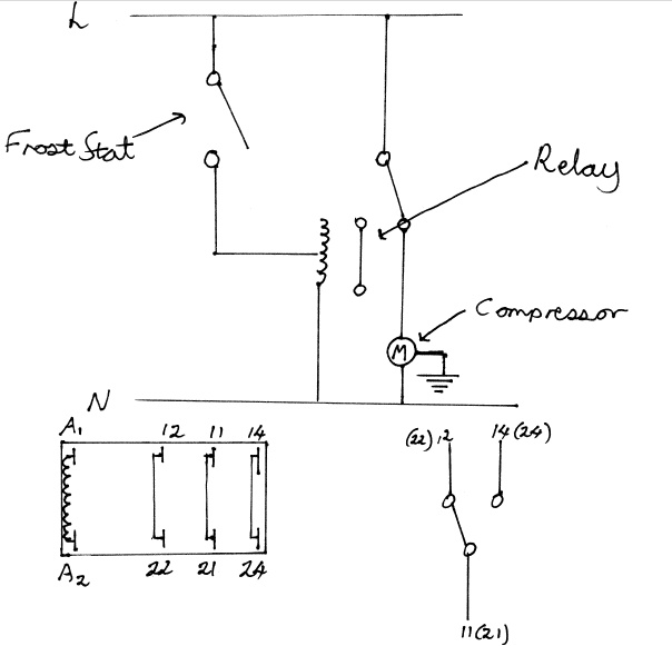
    The basic principle was to install a frost stat in a chest freezer with a temp range of between -5°C and +15°C. After i got the frost stat i realised that it worked the opposite way to what i required. i.e. As the temperature decreases the relay in the frost stat closes and turns on a U.V. lamp. What is needed here is a relay that switches off the compressor in the freezer as it brings down the temperature. Anyway the easiest solution was to use the frost stat to disconnect the normally closed contact on a SPDT (Single pole double throw) relay.

    I know this all sounds a bit out there if you haven't tried a bit of domestic electrical work but it was actually quite easy once i'd drawn up the scematic.

    You can use any frost stat you can lay your hands on, here's the relay i used

    http://cgi.ebay.co.uk/1-x-240V-AC-Miniature-relay-SPDT-16A-/130364581087?pt=UK_BOI_Electrical_Components_Supplies_ET&hash=item1e5a55a4df

    The drawing below shows how the bits are connected up and the pin diagram for the relay
    screen11.jpg


Comments

  • Registered Users, Registered Users 2 Posts: 218 ✭✭Mashtun


    I can put in a bit more detail later if anybody is interested in taking this on


  • Registered Users, Registered Users 2 Posts: 88 ✭✭JnarF


    Mashtun wrote: »
    I can put in a bit more detail later if anybody is interested in taking this on

    I'd be very interested in details please.


  • Registered Users, Registered Users 2 Posts: 218 ✭✭Mashtun


    No bother i took a few pics while i was doing it so I'll get them up later.


  • Registered Users, Registered Users 2 Posts: 218 ✭✭Mashtun


    Right, the reason for having a fermentation chamber is for brewing oktoberfest beers that use yeast like WLP830. This has a fermentation range of 8[FONT=Times New Roman, serif]°[/FONT]C to 12[FONT=Times New Roman, serif]°C [/FONT]which is a good way below room temperature. The main component i used to regulate the temp was a regular frost stat that you would use to stop pipes freezing. This had an ideal temp range of -5[FONT=Times New Roman, serif]°C [/FONT]to +15[FONT=Times New Roman, serif]°[/FONT][FONT=Times New Roman, serif]C[/FONT]. Just to clarify, you're much better off use a regular thermostat as opposed to a frost stat, i had mine bought before i realised i would need to use it in conjunction with a relay for it to work. If you can find a thermostat with the correct temp range this will not be necessary. Here's what i got

    bkbmx.jpg

    Anyway my thinking was to mount the frost stat inside the freezer and run the power cable into the freezer across the realy in the stat and back out again.

    9vequ.jpg

    You can see the mains cable from the compressor going in the left hand side of the hinge and back out the right. I used marine sealant to seal it up but silicone will do the same thing.


  • Registered Users, Registered Users 2 Posts: 218 ✭✭Mashtun


    At this point i should say that my wiring in this does not conform to regulations for domestic wiring. The way i see it is, if you don't know what ur doing steer clear. End of the day i'm not responsible for what you do in the confines of your own home.

    The relay used was one i got off ebay. Make sure it's rated for mains voltage!

    http://cgi.ebay.co.uk/1-x-240V-AC-Miniature-relay-SPDT-16A-/130364581087?pt=UK_BOI_Electrical_Components_Supplies_ET&hash=item1e5a55a4df

    It's important to know how the relay works.

    obhu4.jpg

    The image above shows that there is contact between 11 & 12 when the relay is not active. When the relay is activated there is contact between pin 11 and 14.

    So if the out put from the frost stat can be used to activate the relay, it can be used to deactivate the compressor in the freezer. The image below shows where the pins on the relay are connected to.

    d8nvq.jpg

    Some brown and blue is required for connecting everything up. Best to go a little bit bigger in diameter than the gauge of the wire in the mains cable. I used 1.5mm

    So the first thing to do is peel back the insulation on the mains cable inside the chest freezer. (Make sure not to damage the earth wire!)

    nxbkm.jpg

    The live wire (brown) can be cut and stripped back for inserting into one side of the frost stat. Some brown wire is stripped back and inserted into the same terminal, the other end goes to pin 11 of the relay. The wire is soldered in place. Some more brown wire is used to connect the other side of the relay in the frost stat to pin A1 of the relay. Again this is soldered in place


  • Advertisement
  • Registered Users, Registered Users 2 Posts: 218 ✭✭Mashtun


    The other side of the live wire is then soldered to pin 12. The live wire from the mains cable is the slightly lighter coloured brown wire pictured below.

    twf47.jpg

    Finally the neutral (Blue) cable needs to be connected to pin A2 of the relay. The cable is simply cut, stripped back on both sides and both ends are soldered to the pin.

    And that's it. Ideally as much wire as possible should be concealed in some type of junction box. I mounted everything using and adhesive backed industrial velcro as i did not want to drill into the wall of the freezer.

    It all worked anyway. i left a glass of water in it for a few days and it maintained a steady 10[FONT=Times New Roman, serif]°[/FONT]C [FONT=Times New Roman, serif]
    [/FONT]

    Another thing i hear of is people with cases of wine that are worth a fortune and are a couple of years old end up spoiling in room temperatures in the summer. Problem solved!

    Most importantly electricity can cause fires and electrical shock. I am just a man from the internet who could be talking through my hat so get a qualified electrician to check anything you are unsure of.


  • Registered Users, Registered Users 2 Posts: 88 ✭✭JnarF


    Serious posts!
    Thanks for the info man.


  • Registered Users, Registered Users 2 Posts: 218 ✭✭Mashtun


    Just read through the posts again and i don't think it's as clear as i wanted it to be. One thing i just noticed is that i never explained that the circle with the M inside it is compressor in the chest freezer. Oh well any questions just ask!


Advertisement