Advertisement
If you have a new account but are having problems posting or verifying your account, please email us on hello@boards.ie for help. Thanks :)
Hello all! Please ensure that you are posting a new thread or question in the appropriate forum. The Feedback forum is overwhelmed with questions that are having to be moved elsewhere. If you need help to verify your account contact hello@boards.ie
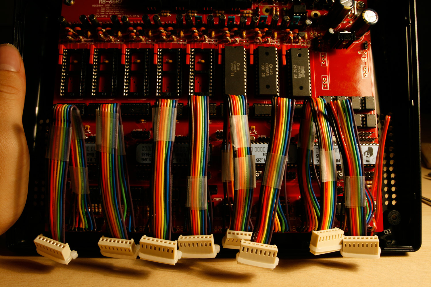
Commodore SID arduino shield PCBs for anyone who wants one
Options
-
04-01-2017 8:06pm#1
Comments
-
-
-
-
-
-
Advertisement
-
-
-
-
-
-
Advertisement
-
-
-
-
-
-
-
-
-
-
-
Advertisement
-
-
-
-
-


 https://www.youtube.com/watch?v=q1OGcqUseLw
 https://www.youtube.com/watch?v=WaBh4ZYE_Ck
 https://www.youtube.com/watch?v=3JM5hNB5CG4
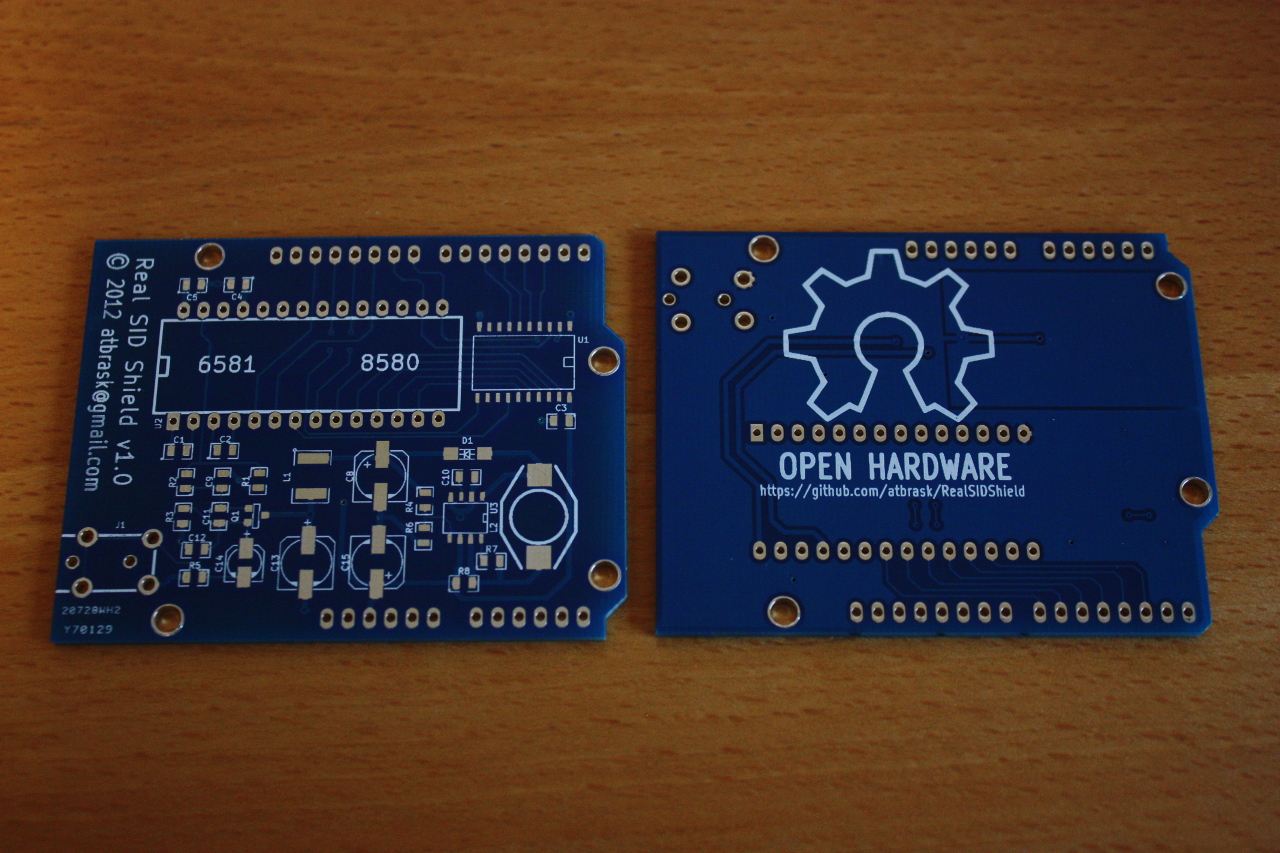
Advertisement