Advertisement
If you have a new account but are having problems posting or verifying your account, please email us on hello@boards.ie for help. Thanks :)
Hello all! Please ensure that you are posting a new thread or question in the appropriate forum. The Feedback forum is overwhelmed with questions that are having to be moved elsewhere. If you need help to verify your account contact hello@boards.ie
Hi all,
Vanilla are planning an update to the site on April 24th (next Wednesday). It is a major PHP8 update which is expected to boost performance across the site. The site will be down from 7pm and it is expected to take about an hour to complete. We appreciate your patience during the update.
Thanks all.

Aritech home alarm wiring diagram

  • 01-10-2019 3:26pm
    #1
    Registered Users Posts: 42


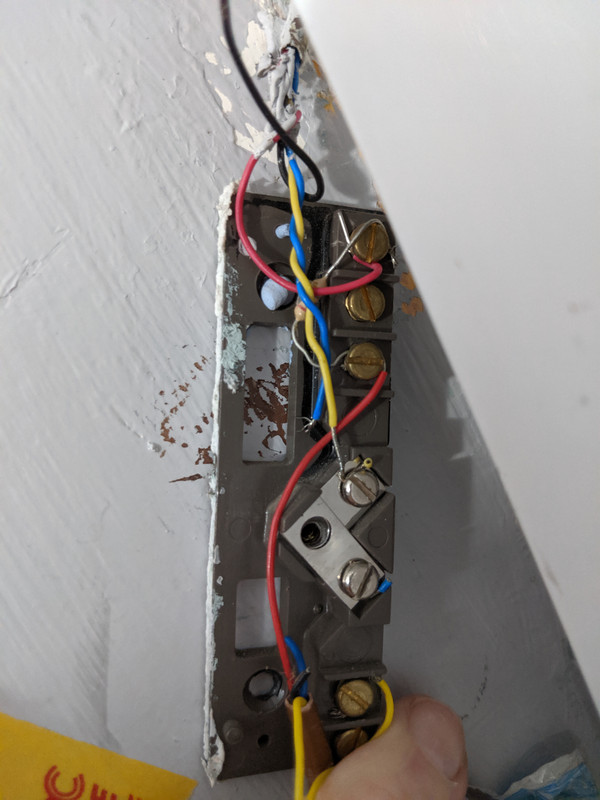
    IMG-20191001-132208.jpgHi,

    I got my front door changed recently and they took off the front door alarm sensor.

    I took a picture of it before it was took off with the assumption I could simply copy it and hook it back up. But now it keeps giving me an open door error.

    I think I need to understand it better. Any chance anyone has a wiring diagram for this system. Or is it as simple as joining two of the wires together to give me at least a closed door so I can set the alarm to work.

    Thanks


Comments

  • Registered Users Posts: 1,813 ✭✭✭NickNickleby


    REmove the magnet from the door, and sellotape it directly to the wired sensor. Its possible that the magnet is too far from the sensor, so if this fixes it you'll know, and its the quickest test I can think of.

    After that, post up the photo you took. Were there only two wires connected? Was there a resistor in the circuit. If the answers are Yes and No respectively, I'd be wondering about the actual cable - was it damaged somewhere along its length during the work?? ( this assumes, without wanting to insult you, that you wired it correctly, so double check - its amazing how easy it is for the wire to not be under the screw after all)

    Not a pro, just a lucky (so far) DIYer - that really should be my nom-de-plume

    edit: sorry, the photo appeared after I posted. Looking at it, seems like the blue wire is cut. Also, this device (assuming its not just a connection block) appears to be in series with something. I think I've an old manual, I'll try to scan in some relevant pages and send them to you.


  • Registered Users Posts: 1,813 ✭✭✭NickNickleby


    Actually, I jsut saw a post that says sharing manuals is prohibited on this forum. So no can do unfortunately.

    However, I know someone posted up a schematic on here in the past, so doing a search of this forum, with Aritech Wiring as your search terms might find it. Sorry.

    Perhaps someone who knows more will come along soon.


  • Registered Users Posts: 42 VidaLoca


    Yes, this is just the connector block at the front door.

    I would have thought if I simply short the red (after the resistor) and the yellow that it would be the same as if the door sensor was closed ?

    But , no. Doesnt seem to be the case.


  • Registered Users Posts: 1,813 ✭✭✭NickNickleby


    Ok, this is just a matter of re-discovering the original connections? Simples, if only.


    As its only a connector block, for most places, you'd expect to see two wires under the screw. Or one wire and one leg of a resistor. So, the two reds on either screw with the resistor across them is a given.

    Now the yellows:

    One is screwed down and is on one side of the tamper, so, what was on the other side of the tamper?? Well, you can see there's a bit of blue insulation on that, so looks like one of the blues belongs there.

    Then you have a yellow on the bottom, Perhaps the remaining blue goes there???

    And remember, the tamper will cause activate if the lid is not properly screwed down.

    Those are my thoughts, and no, they're not even worth a penny :confused:

    Sure give it a lash and see how it goes.

    Once again the caveat : I'm a DIY'er and no doubt one of the pro's will come along and know straight away how this was meant to be wired.

    good luck


  • Registered Users Posts: 72 ✭✭Thewitheredowl


    Hi,

    The black cable needs to be connected with the yellow cable in the terminal circled in red.

    The blue cable that is broken needs to be extended and connected as per the exquisite blue line in the picture


  • Advertisement
  • Registered Users Posts: 42 VidaLoca


    Worked !!!

    Thanks for the help guys.

    Im working my way through changing the faulty contacts. If I have more questions I'll post them here.

    Thanks!


Advertisement