Advertisement
If you have a new account but are having problems posting or verifying your account, please email us on hello@boards.ie for help. Thanks :)
Hello all! Please ensure that you are posting a new thread or question in the appropriate forum. The Feedback forum is overwhelmed with questions that are having to be moved elsewhere. If you need help to verify your account contact hello@boards.ie
Hi all,
Vanilla are planning an update to the site on April 24th (next Wednesday). It is a major PHP8 update which is expected to boost performance across the site. The site will be down from 7pm and it is expected to take about an hour to complete. We appreciate your patience during the update.
Thanks all.
Last of the V8 Interceptors.. my XB Falcon Coupe
Comments
-
Next up for a test fitment where the shiny new adjustable coilovers that I have, again everything is from RRS so my assumption is that all of this kit should play nice together.

Now these do require a tiny modification to the top of the shock towers, here you can see the existing holes that hold the top of the shock mount

Well these existing holes aren t used, so a 5/16 hole need be drilled in the end of the slot so like so


Then you can bolt the coilover in, now the kit comes with a plain steel top collar to spread the load of the bolts across the whole mount, but I won t be using them as I have also bought the strut brace kit & because I m a flashy git I also went of the bling tops to cover them


Installing the coilover is as simple as a 3 bolt installation of anything can be really

Then it was time to see how much effort it takes to install the strut brace, it s a fiddly for a one man job as it s under tension the whole time, you can t adjust the tension once its installed


0 -
You ll notice in the pic above that there is a new bracket on the firewall cowl too, this is a triangulated brace kit, this cowl bracket is supposed to be bolted on, but I m in two minds as to bolt it on or if I should weld it on using the predrilled holes for plugwelds I ll have to think about that


The two braces that go to the firewall can be adjusted for tension after they are installed so there is a lot less swearwords required to install them I found


When I test fit the new engine soon, it ll be interesting to see what if any impact that front bar will have on my air cleaner options. Next job was to install the new knuckles as they call them, these are a beefy piece of kit indeed, they seem very well made

These slide into the opening on the front of the coilover, or at least that s what they are supposed to do mine didn t, nothing major, but they were 1mm too thick so out with the fapping disk on the grinder & I polished them down, you ca see where they are shiny now where I had to take a tiny bit of metal off, I did it in stages so it s almost an interference fit now with no gap or slop at all


Last bit for the night was my new brakes, again all RRS kit I went with 330mm disks & the big six piston calipers, hence the 17 wheels I have it seems such a shame to install the calipers, they look too good to be hidden away, they d look great on display


I m using my old lower control arm right now, but I will be replacing them with a new set of one piece billet control arms as soon as they are ready & shipped to me.

0 -
Ok, so my threads can be found on a few forums & someone on the Falcon Coupe forum asked me for weights of the shiny new RRS stuff & the old stock XB stuff now to be honest the weight loss wasn t really a big factor for me but I did take what they (RRS) said on their website for it all being lighter as being true so in the interest of science & answering your question I took all the new parts off the car again (he owes me a beer) & weighed them & then I weighed the matching original XB bits to see what the difference was. Here are my findings
The RRS power rack (they make a lighter manual one too) complete end to end with tie-rods is 11.4kg.
My stock XB power steering box is 11.9kg, then when you take the end to end links & tie-rods, idler arm etc they are 6.4kg so all up the steering is 18.3kg, so a weight saving of 6.9kg.
The RRS Coilover weights 7.9Kg.
The stock parts that that replaces are the upper arm 6.4kg, the spring 5.6kg & the shock 1.5kg for a total of 13.2kg, so a weight saving of 5.3kg
The RRS knuckle is 7.2kg.
The stock XB spindle is 5.0kg, so the RRS piece is 2.2kg heavier.
I ignored your comment about not weighing the caliper & disks
So the RRS Disk is 9.5kgs.
The stock smaller XB one is also 9.5kg, so no change there other than the fact that the new RRS unit is larger.
The RRS six piston caliper is 4.9kgs.
The stock XB unit is 6.3kg, so 1.4kgs heavier & a lot smaller too.
So if we take the steering out of the equation, the total weight of the suspension per side less the wheel & tire is:
29.5Kg s for the fancy RRS stuff & the stock XB stuff is 32.2kg s so 2.7kg s lighter per side & all up the total weight reduction for both sides & the steering setup is 12.3Kgs
0 -
The more observant of you will have noticed that I hadn t actually completed the suspension & steering install, that was done this morning so on went the new tie-rod ends


The new strut rods

Then it was a complete front end ready for me to check out in full range of movements for any fouling or unwanted contact


I m very happy to report that none was found, I then put on a wheel & did the checks again & again it s all looking real good

I m also happy with the amount of disk & caliper that are showing through the wheel, I think it ll look nice when I m done . Happy with that.

Now with big breaks like this up front there is of course no way I m keeping these at the rear

I have the RRS rear disk conversion to go on, the calipers mini six piston jobs, so there are about the same size as the 4 pot ones I have on the back of the Dodge but are actually 6 pot..

0 -
First job was to remove the old drums, there is so much meat still on these shoes I wonder if the adjusters where actually working & if I was even using the rears towards the end

With the internals removed it s a very simple job of just undoing the 4 nuts through the access hole & then pulling the axle out


With the axle out you then remove the drum backing plate

Then you try to slide on the fancy new backing plate complete with new integrated handbrake shoe mechanism

Then you slowly start to realize that no matter which way you wiggle it, or what angle you start from it s just not going to fit .

Ok, so top tip seems with the Ford had two different ends for their 9 diff s .. what are known as the Small Ford & the amazingly cleverly named Big Ford

So the bracket I have is the larger Big Ford type

But the 9 diff I have is the Small Ford type

Bugger so I ll have to contact RRS & get the backing plates swapped over to suit my diff size now
0 -
Advertisement
-
The last thing that I decided to do today was to start thinking about the engine install & how I was going to connect up the accessories, so the RRS rack comes with a really trick little race pump & fluid reservoir

Now when I say little, its tiny

So now I have to figure out how to fit that to my engine, which is fitted with a fancy electric water pump which means that the standard brackets that bolt to the cast iron or cast aluminum pump housings won t work

If anyone has any ideas I m open to them for now I m thinking that I ll unbolt the pump & remove this blanking plate (the one I m touching in the pic below) & have a new one made up that extends out either side to hold both the Alt & the power steering pump

Then I ll just bolt from the brackets back to the two threaded holes in the aluminum heads for stability

Next job will be to test fit the engine & the massive headers to make sure that they fit & don t foul the steering rack & to make a decision on cutting the shock towers or not stay tuned (or don t, I probably wouldn t)
0 -
I decided it was time to test fit the engine, so that I could then test fit the new much bigger extractors & make sure that everything was going to fit ok or find out now before the car is painted if any body modifications need to be made.
I was never going to use the old thick rubber engine mounts that came out

I have a new set of Tough Mounts (that s the brand, not just a description) for the replacement of both the engine mounts & the gearbox mounts


With the mounts bolted up it was time to swing the engine in


After a little bit of time I decided that whilst it might be cool to own the world s only transverse mounted V8 XB it was probably going to be easier to just mount it normally


It looks nice to have an engine back in there again & it s a great looking engine, even if I do say so myself the driver s side engine mount bolt just slid in, but the passenger side one just wouldn t line up for me & it was getting late & I was getting tired, so I just left it sitting flush on the car mount


0 -
Next day I tried a method a mate told me to try & I loosened off all four bolts that hold the body side of the engine mount to the cross member & that made all the difference, just that extra mm or 2 of movement made the job of getting the passenger side mount bolt in.. too easy


With the engine in place I have clearance between the sump & the cross member.. not heaps, but I can get my fingers in the gap so I m happy with that


The back of the sump also clears the rubber gator of the steering rack by about 5mm now & the back of the engine should come up one the transmission is installed & it s cross member pulls the back of the engine up

Next job was to bolt on the new extractors, they are just a little bigger in diameter that then outgoing ones, I m confident that they ll fit no issues in the engine bay but the big unknown for me was how they would route past the steering rack on the way out

Clearance between the block & the passenger side tower is fine as expected (I m still in two minds as to cutting the towers out to give more room for cooling & ease of access or not, genuinely don t know which way I ll go there)


More importantly clearance of the passenger side extractor over the steering rack is great

0 -
The driver s side extractor is always more of a pain to get in place, I had thought that with the steering box out of the way it would be easier but the brake booster still makes it a pain compared to the passenger side . But no clearance issues

It clears the uni-joints for the steering well too

Clears the rack nicely too

They are bloody wide pipes, it might be fun yet getting them fitted in when they have to wrap around the transmission too

With the engine & extractors all in I decided to refit the brace kit & fit up the carb to see what the top of the engine bay will end up looking like & make sure that it will all fit under the bonnet line


Next job is the fun of trying to fit all the accessories to the front of the engine, so because this is not a stock block or stock heads & because I ve gone with an electric water pump & not the factory style & I currently have some fancy aftermarket mini power steering pump . Well there are just no off the shelf brackets that will bolt up that I can find, I have some choices (as you can see) so I decided to see just how close to making this work I could get


0 -
Now there us a company that sells aftermarket brackets for Ford engines running electric water pumps, but they are for their brand of electric water pump & that pump is just ever so slightly different from mine, so when I went to bolt the brackets on, they were fouling on the pump casing now only by a mm or 2, so not the end of the world I was able to just use the polishing wheel on the grinder to take a tiny bit of material off & make the bracket fit

So close, yet so far

Trying not to completely ruin the shiny bracket


Job done

Now for my big issue with using this style of bracket .. there is no threaded hole in the top of the head to actually bolt the alternator into .

Bugger, so I played with some of the other bits I had & this was the only workable solution I could come up with, bolting the alternator into a threaded hole much lower down on the block itself

Then using an adjustable leg to connect the alt to the bracket

Giving this .


Now this clearly isn t acceptable.. so I have managed to track down a new mount that is a low slung mount that connects to the bottom of the water pump housing & cradles the alt rather than hanging it from above so that s on order now & we ll see how that works when it turns up.
0 -
Advertisement
-
The power steering bracket needed the sort of shaving that the alt bracket needed to be able to bolt onto my water pump

Now the passenger side head has all of the same threaded holes you d see on a factory head, so another option could be to look at mounting the alt on the wrong side of the engine

Then I opted to bolt on the new shiny twin pulley as I knew that this would be easy & that would be a shallow enough victory for the day to make me happy

No doubt there will be fun & games setting up the power steering pump too, but that ll be another day now
0 -
Moderators, Science, Health & Environment Moderators, Society & Culture Moderators Posts: 60,065 Mod ✭✭✭✭
 Join Date:Posts: 58994
Shoot me down in flames if you will, but I actually like the adjustable arm alternator bracket.
Rejoice in the awareness of feeling stupid, for that’s how you end up learning new things. If you’re not aware you’re stupid, you probably are.
0 -
I didn't mind it at first to be honest either, but there are two main reasons that it won't do...
Firstly it's just too long & the result will be a bracket that can flex under load, I had a simular issue with the old power steering pump in my Dodge & it used to drive me nuts as it was fine when at idle or constant speed but when you accelerated the bracket would flex under the load & the belt would squeal.
Secondly it is actually in the space that the battery tray would be taking up, so I'd have to cut a section off the battery tray to fit it back in & then that would make battery placement an issue too.
So an underslung bracket it has to be0 -
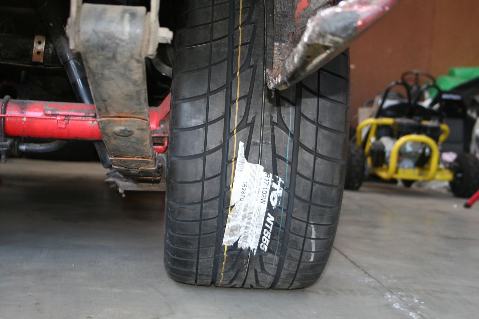
Just a quick update today . The new boots for the Coupe turned up, I ve gone for 245/45ZR17 up front & 315/35ZR17 for the rears

A quick test fit shows that Ford really did get the rear wheel wells right on this car, the rear suspension leaf springs are stock for now & the Guards are not rolled. As you see 315 fits easy

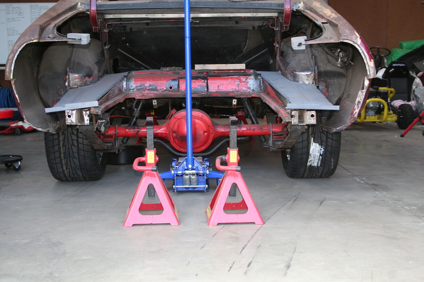
I know that there is no weight in the rear right now but there is plenty of clearance to play with, 20mm from the widest point of the sidewall to the spring (won t matter to me as I m removing the springs anyway)

The tire is still within the guard edge too & there will be no need to roll them if I don t want to (might do it before I paint the car anyway in case I ever go fatter)
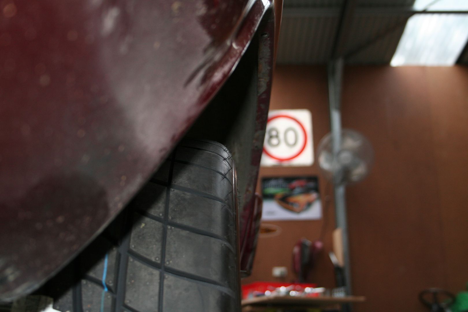


I reckon that 335 s would fit with no mods, they d scrub slightly but they d fit & I reckon that 345 would be possible with rolled guards
0 -
Forgot to say, they are Nitto NT555's.... didn't have a lot of options in the 315/35ZR17 range oddly enough....0
-
The correct RRS backing plate for the rear disk conversion arrived a few weeks ago now, so happy now that I have the correct bracket

As the RRS steering rack required me to hack the end off my stock Steering column to modify it for use with the rack, I decided that I would get another steering column instead so that I could return the steering to stock if I ever needed too. So I decided to go for a fancy tilt column that is already converted for use with the rack, so this should just bolt in the big difference is that it doesn t house the ignition barrel in this column so I ll need to decide where to relocate that too later


The new rear panel that fits across the rear behind the bumper is finished. It looks great & fits really well so very happy with that.


I still haven t fully decided how I m going to fix the chassis rails on this car yet, so I ve decided to give myself as many options as I can to pick from, so on that line of thinking I ordered a set of Mustang rear chassis rails for the 67-73 body style . Now as luck would have it Ford where very lazy back then & there is very little difference between the US Mustang rails & the Aussie Falcon rails, there are two extra bolt holes on the Mustang ones that are not needed on the XB just in front of the rear springe shackle & there are no holes for the XB tramp rods on the Mustang rails & the very ends of the XB rails flange outward vs an inward flange on the Mustang, but all in all they are so close it s not funny


Now the options I have available are:
Leave them badly repaired as they are
Try & heat & pull them back into proper length
Replace the worst sections using sections of Mustang rail
Replace them with the complete Mustang rail
Replace them with the complete rails off my spare XB shell (which are in great condition)
0 -
Next job is to remove the diff from the car, for two reasons.. one so that I can get better access to the rails to work out what to & then to actually do it & secondly so that I can send the diff away to be worked on & toughened up so that it can take the torque of the new engine.
Top tech tip here, it s super easy to remove the diff if you cut the back off your car first . See you don t get tips like that from those US restoration shows now do ya

Should be simple enough, unbolt the brake lines from the diff where connector block mounts

Then unbolt the shock, the sway bar & the tramp rod from where they connect to the car

Getting the tramp rod nut off was hard work, the bolt was worn smooth from years of rubbing on the chassis rail

With all of that undone I just undid the rear shackles & let the diff sit on the wheels pivoting from the front spring perches

Pop those two bolts out & then just wheel the diff back out of the way


Last job of the day was to strip everything off the diff that wasn t going to be needed anymore


Now I just need to make some final decisions as to which way I go fixing the rear rails & the rear Qtrs.. The plan is still to get this car to Hardtop Anniversary in Bathurst next year.. so I need to pull my finger out & spend some long nights in the shed, all of this body work has to be finished by Xmas a tall order but I need to set myself a deadline.
0 -
Nice thread. would love to have the room and patience to do something like this0
-
Love this thread, have been going on a Mad Max binge recently as I'm currently playing the game and finally watched the originals for the first time
 0
0 -
New to Boards.ie and a fellow ex-pat Down Under. Told about this thread by a mate in Dublin. Great work, great detail, keep it up Dave.
Will be following for sure....
Cheers, Aidan0 -
Advertisement
-
Wow, it’s been a long time since I’ve been in this thread. What have I been doing I hear you ask… the answer is a LOT… it feels like I’ve been working on this thing forever now, but the sad truth is that this project is nowhere near where I wanted it to be by now, there are multiple reasons for this but it simply boils down to the fact that I travel too much for work including weekends, add to that the fact that my panel beater can’t always get to me on the weekends I am here. Plus we did make some big decisions & changed the way we went with this & as such made it a bigger job, but if something is worth doing it’s worth doing it half-arsed I say.
Now to save you re-reading the above thread, where I ended up was trying to decide how to fix the bent chassis rails of my XB & how to fix the rear qtr panels that had been butchered to make them fit a car that had bent chassis rails. So hard decisions needed to be made, I had hoped to simply fix my XB & keep my “parts car” XB intact so that I could make a track car out of it, but the harsh reality was that we couldn’t fix the rails, it’s been on a real body shop puller rig & how they are now is as good as they will ever get really… so hard decision number one was to sacrifice my spare XB & take the rear Qtr’s & Chassis rails off it. Hard decision number two was to let my panel beater work on the car without me, he had two weeks off work when I would be away, so I gave him a set of keys to the shed & told him to knock himself out… not I did ask that he take lots of progress pics but that never happened, so there are some stages of the build that I don’t have pics off now… but such is life.
Here is the last time this XB was a complete car… que sad face emoji

Now the chassis rails in this car are perfect & believe it or not the rear Qtrs are really good, the sections that are badly rusted are the common sections & as such repair panels are easily available so fixing them will be a lot easier that sectioning my original qtrs. & reshaping them. Also the rear light panel is in pretty good shape on this Coupe too so the plan will be to reuse that too.
The rear floor had to come out to give us access to the chassis rails so that they can be unpicked from the car


Another new toy was going to be need for this build (can & will be used on the Challenger too) so I bought a rotisserie to allow me to do this properly.. I wonder how the hell they manage to get these things packed into such small boxes?

The instructions that this came with where a joke, it was like someone had described it down the phone to someone else in a different language… so it was an entertaining morning spent with Mrs. XB putting this together

As you can see it was getting late by the time we finished

It’s a very good set up, very adjustable by all counts… & as I’ve been using it for months I can confirm that it was a great buy… very happy indeed

0 -
Up till now the majority of the interior had still been in the car as all of the cutting & welding had been way out back in the boot area, all that was about to change so I needed to strip out the interior so we could get to work on the floor


Now with the seats & carpets out I was able to see the buckling damage to the floor from the rear end accident that was clearly never fixed, so add another thing to the list I guess… the pic doesn’t do this justice but the floor is raised up a good half inch herein the drivers footwell

& badly creased here where the rear seat base joins the trans tunnel
We ground back the paint to find the spotwelds that we’d need to unpick to remove the rear chassis rails


0 -
We needed to melt away the lead that they use as a flexible join for these rear Qtrs so that we could unpick where it joins to the roof

Here you can see where they have butchered the panel to make it fit a bent car rather than fix the car correctly

Both sills are rusted on this car too & the passenger side had some interesting repairs done too over the years, so that had to come off

With that off there was a bit of rust up front that needed to be sorted before the new sill went on


Now sadly we came to a point where I was traveling overseas & my panel beater & one of his mates where smacking my car with hammers & welding & grinding & measuring & prepping & doing all sorts of cool stuff except they weren’t taking any ****ing pictures!! Not even crappy iphone pics… so we pick up the story now at a point where the rear chassis rails have been replaced & the two rear Qtrs have been replaced..
I just love this pic, it’s probably my fave pic of the whole restore for me, it just screams Mad Max to me & that’s the whole reason I fell in love with this car & bought it, this one image has helped me make sense of what a massive job I’ve taken on… all the times I’ve wanted to pour petrol all over it & burn the bloody thing or the times I’ve wanted to use the plasma cutter to make small manageable chunks out it that I can take to the metal recyclers & probably make $350 all up on the scrap value, I can’t explain it but I just smile whenever I see this pic

Luckly they make rust repair sections for all the spots on this Qtr that are bad, so it’s a much quicker & simpler fix that trying to section & reshape my old Qtrs would have been

0 -
Now that the car had good straight rear rails back in the new rear bumper panel was installed to tie them together & the good rear light panel from the spare XB added to give full strength back into the arse of the old girl, next up was to fab up some brackets for the rotisserie so that it would mount up to the bumper mounting holes on the rear


It was finally starting to look like a bloody car again

So we’re about halfway thru the update now… tune in next time, same bat channel….
0 -
Ok, bear with me, we’re almost up to date again….. a bit of an interior strip out was required, ultimately every single part that can be unbolted will be unbolted & it will be an empty shell that I’m working with to ensure that every inch of the car is inspected for rust, repaired & treated. So next out was the steering column


Then I started on removing the dash gauges, I have a few sets of these to pick from when the time to reassemble comes so I’m not sure if these are the exact ones I’ll be using, but as they don’t make any of these bits everything is carefully removed & stored.

The wiring in this car is butchered as you would expect in a 42yro car & the bits that aren’t butchered from countless alarm & stereo installations is simply brittle & cracking, so I think as much as I hate wiring & I really don’t want to do it a complete rewire is on the cards.. I have a few ideas for how I’ll do this but a bit more research is needed before I get to it.. but let’s not get ahead of ourselves.
I also removed the front screen… now I’m not sure if you’ve removed a bonded front screen but I can tell you that there is a reason why when you’re watching American TV car restoration shows they just kick them out… trying to pull one out without damaging it as they are as rare as rocking horse poo is a hard & time consuming task… but the window is out & stored safely with the rest of the glass in one of the guest rooms in the house.

Sadly the Australian company who made the glass for all old Holdens & Fords here never had the foresight to keep the moulds so you cannot get replacement glass for these cars anywhere, you have to hope that someone has one in a shed somewhere they are willing to sell & it’s even worse for the XB Coupe as this is a specific window to this body shape, so the XB Sedan & UTE ones don’t fit.0 -
Next job was the driver’s side sill panel, this one looks bad & it turned out to be a lot worse than the passenger side one. This the section at the front where the A pillar joins up & it’s 3 layers of metal that are all happily rusting together

Not the best think to find when you start cutting away, not sure how I’ll patch this in the end, as in will I use 3 pieces & layer them as Ford did or just us one 3mm thick section to give the same strength but not have the layers that moisture & rust just love to squat in
When I cut the outer sill off I kinda knew what I was going to find underneath & that was that the inner sill was also rusted… good thing I never got T-boned in this car

This A pillar section will need some serious love it seems.. but I have a plasma cutter, grinder, hammers & a welder so just like the $6m man (hopefully at closer to Aldi prices) I’ll rebuild the old girl


Well no point in just staring at it…. Off it came
 0
0 -
Of course by off it came I meant the whole inner sill, I’m either becoming more confident or more delusional as I go with this as I no longer pause before cutting large sections of the car off, I figure if some bloke could make it in the 70’s then there is no reason that I can’t too


Now with the inner sill off I could see some more major rust sections at the A pillar… happy happy joy joy, I was a little worried that that section wasn’t going to be a bastard of a job already… so this is exactly what I hoped to find….

So more grinder action & I mean the angle kind not the App kind


 0
0 -
Right well that’s a few more bits to add to the scrap pile, I’m thinking that I might keep some of the worst sections from this project & hang them on the wall as a reminder to never drive the car in the rain or let it sit overnight wet… only joking this car will be driven & driven hard when I’m done here


I decided then that I’d had enough looking for rust… I’m very good at it apparently, I can find it all over this bloody car… if only it was valuable.. anyway time to start putting some fresh steel back on. I removed the old inner sill in one piece so that I could use it as a template to make up a new section… I used my bead roller to roll in the swage lines that the original panel had for strength, I’m also using slightly thicker steel than Ford did

Once the inner sill was spot welded back onto the floor I was able to mount up the new outer sill panel.. these are the best rust replacement panel that you can buy for this car (there are not many sadly) it’s great quality & very easy to work with as it just fits & you don’t need to massage it much to get it to fit

With that in place the outer sill replacement is a breeze 0
0 -
Even that ****ty A pillar section is starting to come together nicely


Of course I’ll still have to sort out that front floor support section (that for reasons only Ford would know doesn’t actually touch & therefor support the floor) but for now the strength is back in the car as the sill in & the front & rear end caps are on

Let’s see what else have I repaired… ah yes the new boot floors are in, the fuel tank was being used to ensure that the car is actually the right shape.. I swear I’ve taken a thousand measurements & triple checked everyone at every stage of this rebuild but sometimes it’s nice to get the simple reassurance of seeing an original part fit perfectly where it was supposed to go

The floor to bumper support panel brackets are in too
I said earlier that I was able to reuse the tail light panel from the other XB which is a great thing as the ribbed lines in the replacement panels you can get are just not right… I did however have to replace the lower section of this panel using the new shaped metal from the rust repair panel I had bought 0
0 -
Advertisement
-
There is lots of little tricky sections that I’ve had to repair too & lots of small patch panels I’ve had to make like here on passenger Qtr


The inner wheel tubs have needed lots of little patches made up too… good thing this isn’t a show car & it never will be.. but it will be a rust free one when I’m done


 0
0


Advertisement