Advertisement
If you have a new account but are having problems posting or verifying your account, please email us on hello@boards.ie for help. Thanks :)
Hello all! Please ensure that you are posting a new thread or question in the appropriate forum. The Feedback forum is overwhelmed with questions that are having to be moved elsewhere. If you need help to verify your account contact hello@boards.ie
Hi all,
Vanilla are planning an update to the site on April 24th (next Wednesday). It is a major PHP8 update which is expected to boost performance across the site. The site will be down from 7pm and it is expected to take about an hour to complete. We appreciate your patience during the update.
Thanks all.

HKC SecureWatch - Zone/Tamper inhibit

  • 08-02-2013 6:13pm
    #1
    Registered Users Posts: 3,570 ✭✭✭


    UPDATE: Skip to Post #6 & #7 for latest


    Background:
    I have a HKC SecureWatch alarm with a fault at the minute in Zone 3. I suspect that the fault is due to damage to the wire when drilling for mounting a blind for the window. Bold me! :( The damage is potentialy to the last sensor in the chain for this zone. My original alarm installer has gone off to Australia so I don't have access to the engineer code.

    Two questions:

    1. There are 3 items, 2 windows & a door on this zone & the tamper circuit works fine on all of them. That is when I remove the cover from any of the sensors in this zone the alarm goes off. I want to be able to temporarily disable the tamper system while I'm removing the sensor covers. Does the tamper circuit get inhibited as well as the other part of the sensor when I type 0 CODE * 3 Yes?
    2. I want to prove out that it is damaged wiring that is causing the problem as it might have just been a coincidence. Can I use a short piece of wire between any of the terminals to fool the alarm in to thinking the circuit is closed? If so what terminals should I use on the sensor?

    To me it looks like my sensors are wired like the Dual End of line wiring diagram attached that I borrowed form one of Altor's posts. Except there are no 4k7 resistors, only short lengths of wire where the resistors are indicated in the diagram. If I short between terminal 3 & terminal 5 (going left to right in the picture/diagram) in Sensor 1 would that help me prove out that the wiring (or sensor) is faulty? Can I do something similar for each of the thre sensors in the zone? I've never worked on alarms but I do have a very good understanding of electronics, I just can't make out what is happening with terminal 4 & 6. I don't have a spare sensor to hand to follow the circuit board.
    Any help is appreciated.


Comments

  • Moderators, Home & Garden Moderators, Technology & Internet Moderators Posts: 24,789 Mod ✭✭✭✭KoolKid


    To close off a tamper close off the cables going into terminals 3 & 4 .


  • Registered Users Posts: 11,637 ✭✭✭✭altor


    Background:
    I have a HKC SecureWatch alarm with a fault at the minute in Zone 3. I suspect that the fault is due to damage to the wire when drilling for mounting a blind for the window. Bold me! :( The damage is potentialy to the last sensor in the chain for this zone. My original alarm installer has gone off to Australia so I don't have access to the engineering code.

    Two questions:

    1. There are 3 items 2 windows & a door on this zone & the tamper circuit works fine on all of them. That is when I remove the cover from any of the sensors in this zone the alarm goes off. I want to be able to temporarily disable the tamper system while I'm removing the sensor covers. Does the tamper circuit get inhibited as well as the other part of the sensor when I type 0 CODE * 3 Yes?
    2. I want to prove out that it is damaged wiring that is causing the problem as it might have just been a coincidence. Can I use a short piece of wire between any of the terminals to fool the alarm in to thinking the circuit is closed? If so what terminals should I use on the sensor?

    To me it looks like my sensors are wired like the Dual End of line wiring diagram attached that I borrowed form one of Altor's posts. Except there are no 4k7 resistors, only short lengths of wire where the resistors are indicated in the diagram. If I short between terminal 3 & terminal 5 (going left to right in the picture/diagram) in Sensor 1 would that help me prove out that the wiring (or sensor) is faulty? Can I do something similar for each of the thre sensors in the zone? I've never worked on alarms but I do have a very good understanding of electronics, I just can't make out what is happening with terminal 4 & 6. I don't have a spare sensor to hand to follow the circuit board.
    Any help is appreciated.

    If you don't have engineer access to the alarm then the only way to find out if it is wired duel end of line or non end of line would be to check both the last sensor on the loop or the control panel itself. I presume you have checked the sensors. If you turn off the mains to the control panel and open, alarm will activate, just enter your code to turn off. Check to see if resistors are fitted it the zone in question. Another thing to check in this zone is if the alarm is the only part of the zone wired. If so the it may be dual, single or non end of line. If both alarm and tamper is wired in this zone it may be non end of line. If the tamper of the zone has cables connected to it then you could also close off the tamper here if wired non end of line.


  • Registered Users Posts: 3,570 ✭✭✭rebel.ranter


    KoolKid wrote: »
    To close off a tamper close off the cables going into terminals 3 & 4 .

    Hi, I was hoping that I could temporarily disable the tamper in the zone so I don't annoy the neighbours when I'm removing the sensor cover. Its the alarm cicuit that I want to temporarily close off with the piece of wire.


  • Registered Users Posts: 11,637 ✭✭✭✭altor


    Hi, I was hoping that I could temporarily disable the tamper in the zone so I don't annoy the neighbours when I'm removing the sensor cover. Its the alarm cicuit that I want to temporarily close off with the piece of wire.

    If you take the lid off the control panel as explained above then put in your user code this will stop the alarm ringing while you are working on it. You really need to determine which way the zone is configured.


  • Registered Users Posts: 3,570 ✭✭✭rebel.ranter


    altor wrote: »
    If you take the lid off the control panel as explained above then put in your user code this will stop the alarm ringing while you are working on it. You really need to determine which way the zone is configured.

    Thanks for that, I knew that but I was just trying to see if there was a code that I could enter in to the keypadto prevent the alarm sounding when I opended the sensor (or the control panel). That's probably what the engineer code does I suppose?

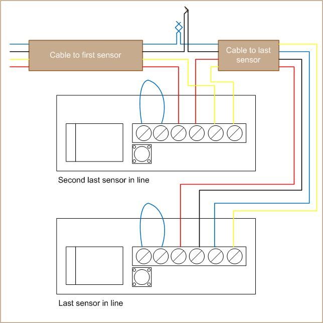
    Anyway, I traced my problem. It was down to the drilling alright. I temporarily removed the last in line sensor from the zone by wiring the second last in line sensor the same way as the original last in line was wired. With the wiring for the last sensor out of the circuit I just buzz tested each of the four wires & found that the yellow one failed the continuity test. The other three were fine. With the final sensor out of the loop it at least means I can arm the alarm until I figure out how best (cosmetically) I can get an alterative feed for the broken yellow wire.
    Luckily there is an attic above the window so I can access the cable there, its just bringing it down to the sensor at the window is the problem. I have the fibre glass rods that will help me run the wire inside the hollow piece of the wall between the plaster board & brick, unfortunately it is on the right side of the window (sensor on left side of course). So I'll just have to fgure
    out how to run it inside the reveal.

    I didn't bother opening the control panel to see what way the alarm was wired. I recently replaced the back up battery & I think the neighbours endured enough of my alarm going off!
    Anyway I just said i'd draw up how the last two sensors in zone 3 were wired up. Out of curiosity more than anything can you tell from this what wiring scheme was used?

    AlarmSensor_zps3d9b94c1.jpg


  • Advertisement
  • Registered Users Posts: 3,570 ✭✭✭rebel.ranter


    By the way guys, thanks for taking the time to reply to my thread. Much appreciated.

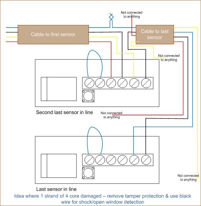
    I just had another thought. Now that I have discovered that 3 out of 4 of the strands in my 4 core wire are OK (yellow wire damaged) can I wire up the last sensor in the line without bringing the tamper detection into the loop?

    I was thinking that I could close the tamper loop at the second last sensor & then use the black & blue wire to bring the shock/open window detection circuit (sorry if terminology is not correct) from the last sensor. Like the schematic below:

    AlarmSensor-brokenwire_zpsf6aa8026.jpg

    I know the tamper detection wouldn't work but wuld the other circuit work? I suppose I am really asking if the tamper & shock are independent circuits? Would I need to put a loop between terminal 3 & terminal 4 too, I don't think I would but no harm in asking.


  • Registered Users Posts: 3,570 ✭✭✭rebel.ranter


    Just to update, this works just fine. I've no tamper protection on one window sensor but the rest of the sensor works as it should.


  • Registered Users Posts: 16 smurfette2


    Hi can anybody tell me what I need to do to set my alarm without arming the kitchen sensor which is called zone4.

    0#4 is the full set code and 0#7 is what I press going to bed.


  • Registered Users Posts: 6,528 ✭✭✭kub


    smurfette2 wrote: »
    Hi can anybody tell me what I need to do to set my alarm without arming the kitchen sensor which is called zone4.

    0#4 is the full set code and 0#7 is what I press going to bed.

    To set it while inside 0#7 * 4 Yes. ( Yes middle button to right)

    To set it while leaving the house 0#4 * 4 Yes.


Advertisement